
Neither pneumatic nor electric valve actuation is universally better. Choose between them by comparing the valve’s required torque or thrust, permitted mechanical load, stroke time, defined failure action, available utilities and lifecycle cost. Existing instrument air may favor a pneumatic package; an available electrical supply may favor electric actuation. Both can support on/off or modulating duty when properly configured. This comparison helps engineers and buyers normalize RFQs and identify the evidence needed before approving a complete valve–actuator package.
Pneumatic vs Electric Valve Actuators: Quick Comparison
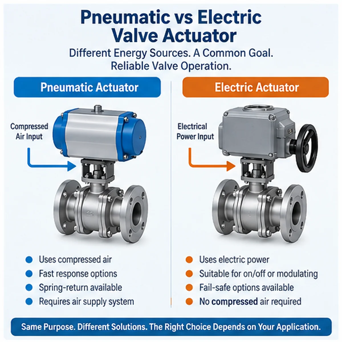
The main difference is the energy source. Pneumatic actuators use compressed air to produce mechanical movement, while electric actuators use an electric motor and transmission mechanism. That distinction affects the supporting equipment, control arrangement and response to utility failures.
| Фактор выбора | Пневматический привод | Электропривод |
|---|---|---|
| Energy source | Сжатый воздух | Electrical power |
| Выходной крутящий момент | Depends on actuator design, air pressure and stroke position | Depends on motor, gearing, torque limits and duty rating |
| Рабочая скорость | Can be suitable for rapid operation, subject to sizing and air-system capacity | Depends on motor, gearing and control configuration; fast options may be available |
| Аварийное положение (Fail-safe) | Spring-return and other arrangements can provide a defined action | Requires a suitable fail-safe arrangement when movement after power loss is required |
| Регулирующая функция | Suitable for on/off and modulating service with appropriate accessories | Suitable for on/off and modulating service with appropriate controls |
| Инфраструктура | Air supply, filtration, regulation and associated equipment | Electrical supply, protection and associated equipment |
| Lifecycle cost | Influenced by compressed-air infrastructure and operation | Influenced by electrical infrastructure, duty and maintenance |
This table is a screening tool. It does not establish that one technology is always faster, stronger, safer or less expensive. For definitions and working principles, see Valve actuator fundamentals. This article focuses on comparing pneumatic and electric packages for a defined valve duty rather than replacing a complete actuation selection guide.
Torque: Match the Actuator to the Valve, Not Just the Nameplate
Required Valve Torque Across the Stroke
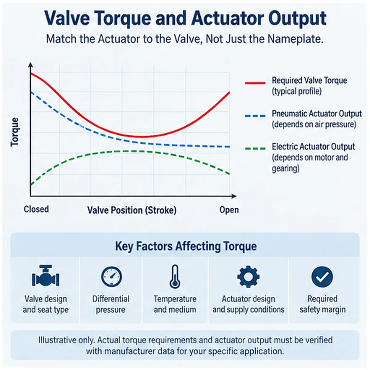
Valve torque is not necessarily constant throughout operation. The actuator may need to overcome different loads during initial movement, travel and final seating. The relevant torque data depend on the valve construction, seat design, pressure differential, temperature and service conditions.
For quarter-turn valves, the review commonly includes breakaway, running and seating or unseating requirements. For multi-turn valves, the required thrust or torque, number of turns and operating arrangement must also be considered. A nominal valve size or pressure class is not enough to determine the actuator.
A typical RFQ mistake is to compare a single breakaway torque with the actuator’s advertised maximum output. That can miss the required load elsewhere in the stroke and the maximum torque the valve stem or gearbox can accept. Request the required and allowable loads by direction and position, then check both the minimum available actuator output and the maximum transmitted load. This is a review method, not a calculation for a particular model.
Pneumatic Torque Output and Air-Supply Conditions
Pneumatic actuator output depends on its mechanism and the available air pressure. In spring-return arrangements, the spring and air strokes have different output characteristics, so both must be checked against the valve’s required torque. The review should include the minimum available supply pressure, not only the nominal plant-air pressure. Air regulators, tubing, solenoid valves and other accessories may also affect the complete package.
Electric Torque Output, Limits and Duty Rating
Electric actuators use a motor and gearing to deliver the required output. Their suitability depends on the manufacturer’s torque data, operating limits, duty rating and the valve’s movement requirements. A high advertised maximum torque does not, by itself, prove that an actuator is suitable for the intended duty. The complete operating cycle, starts, control frequency and thermal limitations should be reviewed.
Torque switches, motor protection and travel limits must be reviewed as part of the selected configuration. A torque limit is not automatically a guarantee that every stem, coupling or gearbox load remains below its allowable value. The supplier should confirm the setting, tolerance and maximum transmitted load against the mechanical interface limits.
Actuator Torque Matching: Evidence Required Before Approval
The actuator should be matched to the valve’s required torque or thrust over the relevant operating range. A single maximum-output value is not sufficient when the valve load or actuator output changes during travel. For the broader drive-method selection framework, see Valve actuation and drive mode selection.
| Пункт проверки | Требуемые доказательства | Вопрос об утверждении |
|---|---|---|
| Valve operating load | Manufacturer torque or thrust data for the specified valve and service | Does the data cover the relevant differential pressure, temperature and seat condition? |
| Pneumatic output | Actuator output data at the specified minimum supply pressure | Is sufficient output available throughout the required stroke, including the spring stroke where applicable? |
| Electric output | Manufacturer torque data, torque limits and duty information | Can the actuator deliver the required output without exceeding its operating limits? |
| Torque margin | Supplier’s documented matching calculation and assumptions | Is the proposed margin appropriate for the project specification? |
| Механическое присоединение | Confirmed mounting, coupling and stem/interface requirements | Is the complete valve–actuator connection suitable for the transmitted load? |
| Functional verification | Agreed inspection or functional-test scope | Will the assembled package demonstrate the required operation? |
| Maximum allowable mechanical load | Valve manufacturer’s allowable stem torque or thrust, gearbox and coupling limits, and proposed actuator maximum output | Can the package meet the required load without overstressing the valve or transmission? |
| Direction and position | Required and allowable loads by opening/closing direction and relevant stroke position | Have both directions and the controlling load cases been reviewed? |
For a concrete example of this two-sided review, see Emerson’s FieldQ actuator sizing data sheet. Its example is model-specific and must not be reused as a universal torque margin or Raymon Valve performance claim.
Граница выбора: Do not approve an actuator solely because its advertised maximum torque exceeds one valve torque value. The matching calculation must reflect the relevant operating conditions and the complete package. No final actuator size should be assigned without these inputs.
Operating Speed: Specify the Required Stroke Time
What Determines Pneumatic Stroke Time?
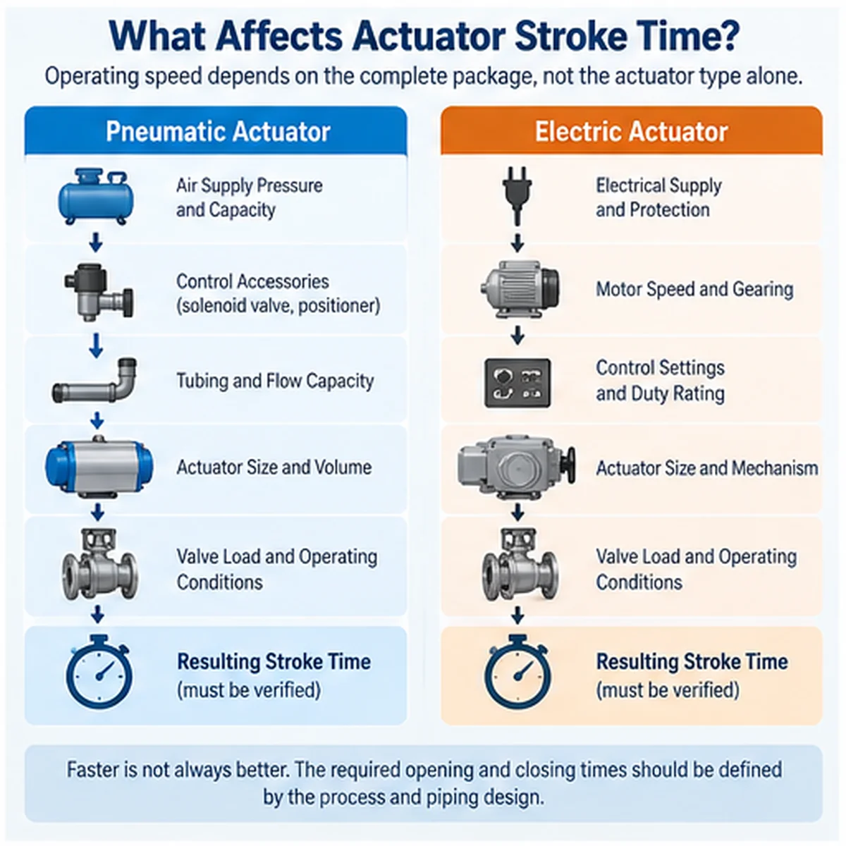
Pneumatic operating time depends on actuator volume, supply pressure, air-flow capacity, tubing, control accessories and valve load. A larger air supply or a different control arrangement may change the result, but the complete package must be verified.
What Determines Electric Stroke Time?
Electric operating time depends on motor speed, gearing, control settings, load and actuator design. Some electric actuators are intended for relatively slow movement, while other configurations are designed for faster operation. The technology label alone is not a reliable stroke-time specification.
Fast Closure, Water Hammer and Process Consequences
Faster is not always better. Rapid valve movement can create undesirable pressure transients in certain liquid systems or disturb process operation. The required opening and closing times should therefore come from the process and piping design, not simply from the fastest available actuator.
Define Stroke-Time Acceptance Conditions
A useful stroke-time requirement identifies the complete valve and actuator package, the operating conditions and the acceptance method. “Fast operation” is not a measurable specification.
A useful procurement check is to compare two offers that both claim “fast closing.” One may quote an unloaded actuator time; the other may include the valve, accessories and minimum utility condition. Require both suppliers to state the same test boundary and acceptance conditions before comparing their figures. If the required time is linked to a process transient or shutdown demand, obtain the responsible engineer’s approval of that time rather than selecting the fastest unit.
The RFQ should state the required opening and closing times, the relevant load or differential pressure, the minimum available air pressure or specified electrical supply, and the accessories included in the test. Where timing is critical, the supplier should confirm whether the requirement applies to normal operation, an emergency demand or both.
For pneumatic packages, air-flow restrictions, tubing and control accessories may affect the result. For electric packages, motor and gearing characteristics, control settings and duty limitations may affect the result. The final time should be confirmed for the selected configuration.
Process boundary: A shorter closing time is not automatically safer. Where rapid movement could create pressure transients or other process consequences, the required timing should be reviewed by the responsible process and piping engineers.
Fail-Safe Action: Define the Failure Before Selecting the Actuator
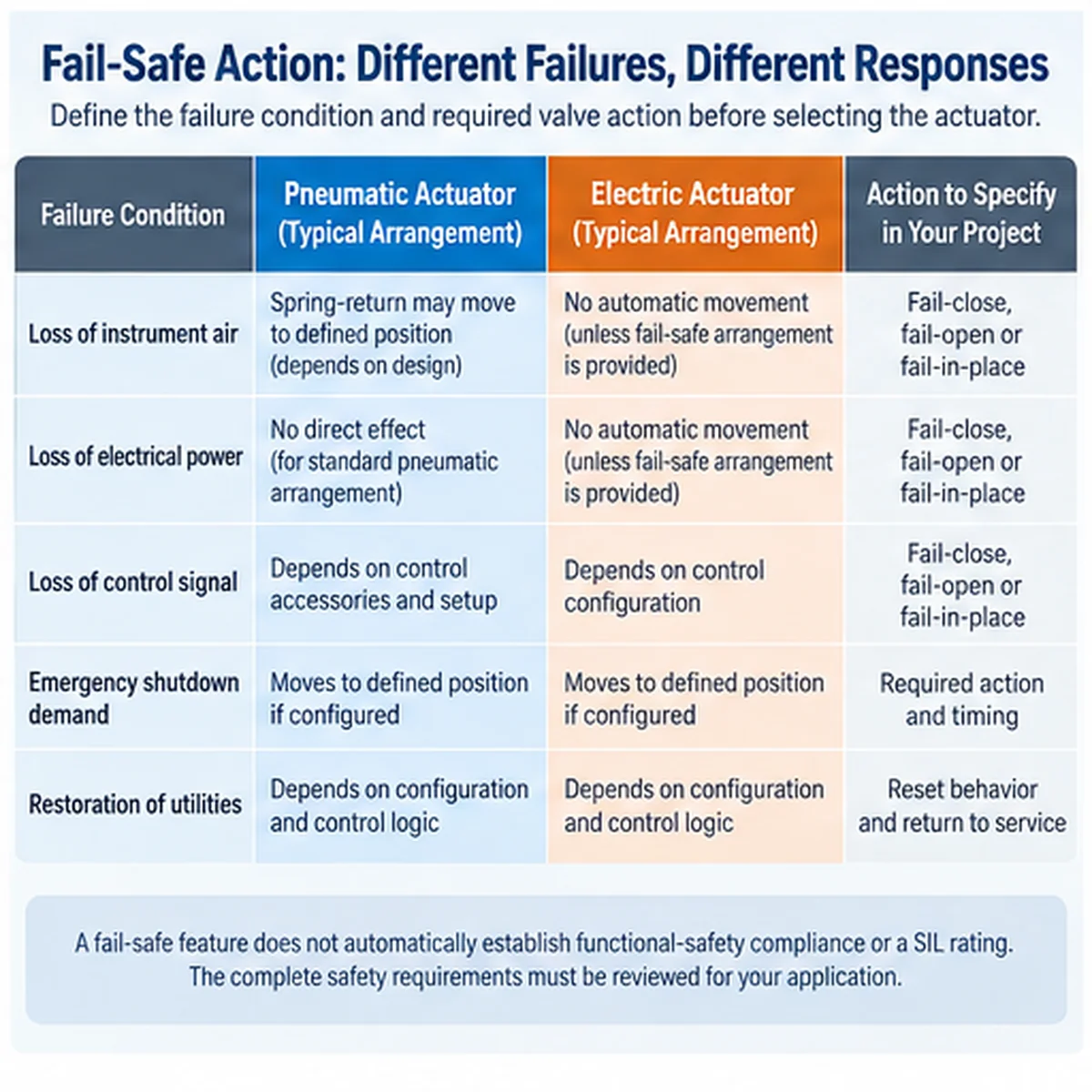
A fail-safe requirement must describe what happens, under which failure condition, and within what time. “Fail-close” is incomplete if the project does not identify whether the triggering event is loss of air, loss of electrical power, loss of control signal or another defined condition.
Fail-Close, Fail-Open and Fail-in-Place
Fail-close and fail-open describe movement to a defined position under a specified failure condition. Fail-in-place describes an intended response to remain in or near the last position, subject to the actual configuration. These are functional requirements, not guarantees of process safety.
Pneumatic Spring-Return and Double-Acting Arrangements
A pneumatic spring-return actuator can use stored spring energy to move the valve toward a defined position when the relevant air pressure is removed. The available spring torque must still be sufficient for the valve under the specified conditions. A double-acting arrangement generally relies on air pressure for movement in both directions; its behavior after air loss depends on the circuit, load and additional equipment.
Electric Fail-Safe Options and Their Limitations
Electric actuators can be configured with suitable arrangements to achieve a defined failure action, depending on the product and project requirements. A standard electric actuator should not be assumed to move to a safe position after loss of power. The available energy, required movement, load and failure scenario must be checked against the specific design.
Electric actuation does not necessarily mean “fail-in-place.” For example, Rotork’s ELC 250SR product page describes an electric linear actuator with a spring-return mechanism for loss of power. This demonstrates that a defined failure movement is possible, not that every electric actuator provides it. The selected model, energy arrangement and complete-package test remain decisive.
Fail-Safe Verification Matrix
The project should define the required response for each relevant failure. The same actuator may behave differently depending on its accessories, control circuit and available stored energy.
| Scenario | Requirement to define | Доказательства для запроса |
|---|---|---|
| Loss of instrument air | Required valve position and response time | Pneumatic schematic, actuator configuration and functional-test procedure |
| Loss of electrical power | Required valve position and response time | Electrical schematic, fail-safe arrangement and available-energy confirmation |
| Loss of control signal | Required valve response | Control logic, positioner/controller configuration and test procedure |
| Emergency shutdown demand | Required action and timing | Project safety requirements and complete-package functional verification |
| Utility restoration | Required reset or return behavior | Control philosophy and operating procedure |
For safety instrumented applications, the IEC 61511-1:2016+AMD1:2017 consolidated edition addresses requirements for the specification, design, installation, operation and maintenance of process-industry safety instrumented systems. It does not establish a SIL claim for an individual actuator or a Raymon Valve package. The applicable project edition and complete safety-function evidence must be confirmed.
Важно: A spring-return actuator does not automatically satisfy every failure scenario, and an electric actuator with stored energy does not automatically satisfy a project’s safety integrity requirements. Where the assembly is part of a safety instrumented function, the complete safety function and applicable project requirements must be evaluated.
Lifecycle Cost: Compare the Complete Installed Package
The lowest actuator purchase price may not produce the lowest lifecycle cost. A meaningful comparison uses the same valve duty, project life, operating frequency and scope of supply.
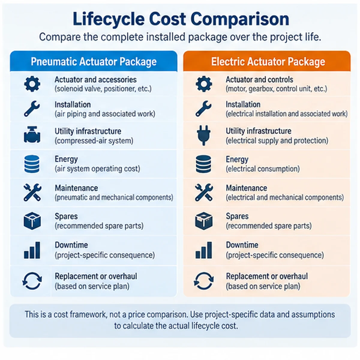
Initial Equipment and Installation Scope
Pneumatic quotations may include the actuator, solenoid valve, air filter regulator, positioner, tubing, fittings and other accessories. Electric quotations may include the actuator, controls, electrical protection, cabling and related equipment. The exact scope varies.
Compressed Air, Electricity and Utilities
Where plant air already exists, the incremental pneumatic infrastructure may be limited. Where it does not exist, compressors, air treatment and distribution may materially affect cost. Electric systems require a suitable electrical supply and protection arrangement, including any required backup provisions.
Maintenance, Spares and Downtime
Maintenance costs depend on design, operating frequency, environment and supporting equipment. Neither technology should be described as maintenance-free. The supplier should provide the recommended maintenance scope and spare-parts information for the selected model.
Normalize the Quotation Before Comparing Lifecycle Cost
Two actuator quotations are not directly comparable unless they cover the same service duty and supply scope. The buyer should request a clear list of inclusions, exclusions and items supplied by others.
| Cost boundary | Pneumatic quotation | Electric quotation |
|---|---|---|
| Actuator and mounting | Confirm included components | Confirm included components |
| Control accessories | Solenoid, positioner, regulator and other specified items | Controls, feedback and other specified items |
| Utility connection | Air tubing, fittings and distribution interface | Cabling, protection and electrical interface |
| Infrastructure allocation | Compressed-air generation and treatment, where applicable | Electrical distribution and backup, where applicable |
| Энергетика | Project-specific compressed-air operating cost | Project-specific electrical consumption |
| Техническое обслуживание | Recommended service tasks and intervals | Recommended service tasks and intervals |
| Spares | Recommended spare-parts list | Recommended spare-parts list |
| Downtime | Project-specific consequence | Project-specific consequence |
| Documentation and testing | Agreed scope | Agreed scope |
| Replacement or overhaul | Project-specific overhaul or replacement allowance | Project-specific overhaul or replacement allowance |
A practical comparison starts with the same project life and operating profile, then adds purchase, installation, allocated utility infrastructure, energy, planned maintenance, spares and expected downtime costs. Avoid counting a shared compressor or electrical installation twice. For an existing plant-air system, record the incremental air demand and allocation basis; for a new installation, include the required generation and treatment scope. A lower actuator purchase price is not enough to establish a lower total cost.
The lifecycle comparison should use the same project life, operating frequency, utility assumptions and maintenance basis. Any cost advantage should be supported by the quotation and calculation rather than a generic percentage claim.
Which Actuator Should You Choose?
The following matrix provides a preliminary direction for comparing pneumatic and electric packages, not a complete actuator selection procedure.
| Project condition | Предварительное направление | Required verification |
|---|---|---|
| Reliable instrument air is available | Pneumatic may be practical | Minimum air pressure, quality and capacity |
| No compressed-air infrastructure | Electric may simplify utilities | Power supply, backup and installed cost |
| Defined spring-return action | Pneumatic spring-return is a common option | Spring torque throughout the required stroke |
| Electric actuation with required failure movement | Consider a suitable fail-safe arrangement | Stored energy, failure scenario and package test |
| Frequent modulating service | Compare both configurations | Duty rating, control performance and maintenance |
| Tight stroke-time requirement | Compare verified package performance | Stroke time under specified load and utilities |
| Remote or difficult-maintenance installation | Compare complete lifecycle requirements | Diagnostics, access, spares and recovery procedures |
RFQ Checklist for Pneumatic and Electric Actuator Packages
A complete RFQ helps suppliers propose comparable packages and reduces technical deviations.
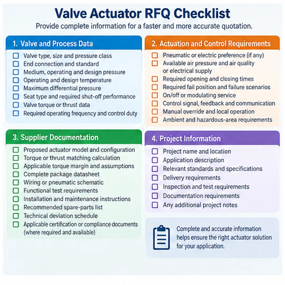
Valve and Process Data
- Тип клапана, размер, класс давления и тип присоединения
- Medium, operating and design pressure and temperature
- Maximum differential pressure relevant to operation
- Seat type and required shut-off performance
- Valve torque or thrust data, including relevant operating conditions
- Required operating frequency and control duty
Actuation and Control Requirements
- Pneumatic or electric preference, if any
- Available air pressure and air quality, or electrical supply
- Required opening and closing times
- Required fail position and defined failure scenarios
- On/off or modulating service
- Control signal, feedback and communication requirements
- Manual override and local operation requirements
- Ambient and hazardous-area requirements, where applicable
Документация поставщика
- Proposed actuator model and configuration
- Torque or thrust matching calculation and assumptions
- Complete package datasheet
- Functional test requirements
- Wiring or pneumatic schematic, as applicable
- Installation and maintenance instructions
- Recommended spare-parts list
- График технических отклонений
- Applicable certification or compliance documents, where required and available
- Maximum allowable stem/gearbox/coupling load and protection settings
- Package scope and technical deviations, including items supplied by others
- Applicable project specification and agreed acceptance criteria
- Required test records and documentation delivery schedule
For company background, see О Raymon Valve. Product-specific capabilities, certifications and test results should be confirmed through the relevant documents rather than assumed from general company information.
Technical Bid Evaluation and Approval Gate
Before purchase approval, request each supplier to identify deviations from the project specification. A lower-priced package should not be accepted without reviewing differences in torque matching, operating time, fail-safe behavior, accessories, testing and documentation.
| Approval item | Required status |
|---|---|
| Valve torque or thrust data received | Confirmed / Pending |
| Actuator matching calculation reviewed | Confirmed / Pending |
| Minimum air pressure or electrical supply confirmed | Confirmed / Pending |
| Opening and closing times confirmed | Confirmed / Pending |
| Failure scenarios and required positions defined | Confirmed / Pending |
| Control accessories and interfaces included | Confirmed / Pending |
| Environmental and hazardous-area requirements reviewed | Confirmed / Pending |
| Functional-test scope agreed | Confirmed / Pending |
| Documentation and spare-parts scope agreed | Confirmed / Pending |
| Technical deviations resolved | Confirmed / Pending |
| Maximum allowable mechanical loads and protection settings reviewed | Confirmed / Pending |
| Quotation scope, utility allocation and lifecycle assumptions normalized | Confirmed / Pending |
| Failure-action test conditions and restoration behavior agreed | Confirmed / Pending |
Правило утверждения: Any unresolved item that affects safe operation, required performance or contractual acceptance should remain open until the responsible engineering and procurement teams approve the proposed solution.
Final Selection and Engineering Approval
The correct actuator is the one that satisfies the valve’s operating requirements and the project’s failure, control and lifecycle conditions. Pneumatic and electric technologies should be compared using the same service data and supply scope.
Before purchase approval, confirm the valve torque requirements, actuator output, required operating time, failure behavior, utilities, environmental suitability and documentation. Where the application involves emergency shutdown or another safety function, the responsible engineering team should review the complete assembly and the applicable safety requirements.
For related valve selection and control-duty considerations, review the Регулирующие клапаны category and the База знаний. Product-specific actuator matching still requires the complete datasheet.
Request Actuator Matching Support
Send the valve datasheet, required and allowable torque or thrust data, maximum operating differential pressure, required stroke time, available air or electrical supply, control duty, defined failure scenarios and project documentation requirements. Request a package-specific matching review and technical quotation.
Submit Your Valve DatasheetЧасто задаваемые вопросы
Is a pneumatic actuator always faster than an electric actuator?
No. Actual stroke time depends on actuator design, utilities, accessories and valve load. Compare verified package performance against the required opening and closing times.
Which actuator provides more torque?
Neither technology is universally stronger. The correct comparison is between the valve’s required torque and the actuator’s available output under the specified conditions.
Can an electric valve actuator be fail-safe?
Yes, suitable arrangements can provide a defined failure action. The capability depends on the design, available stored energy and failure scenario and must be verified for the complete package.
What happens to a pneumatic actuator when air supply is lost?
The response depends on the configuration. Spring-return arrangements may move toward a defined position, while double-acting arrangements depend on the pneumatic circuit, load and additional equipment.
Is pneumatic or electric actuation cheaper over its lifecycle?
It depends on infrastructure, operating frequency, maintenance and downtime. Compare complete installed packages using the same project assumptions.
What information is required to size a valve actuator?
Provide the valve type, relevant torque or thrust data, operating differential pressure, required stroke time, duty, available utilities and fail-position requirements. Final selection requires manufacturer confirmation.
 Russian
  English
  German
  Arabic
  French
  Spanish
  Italian
  Portuguese