
Testing & commissioning · Engineering guide
FAT vs SAT: What Each Test Should Prove
For actuated valve packages, a Factory Acceptance Test (FAT) checks the agreed assembly and functions before shipment; a Site Acceptance Test (SAT) checks the installed package and its defined site interfaces. Buyers need both scopes clearly allocated because factory simulation cannot prove excluded field wiring, installed utilities or cross-system interlocks. Specify commands, feedback, failure and restoration cases, timing endpoints and tag-linked acceptance records before testing. Use the comparison and checklists below to decide which factory evidence can carry forward and which requirements still need site verification.
For buyers, the practical question is which requirement each test proves—and which requirements remain open. Agree this allocation before quotation so that factory simulation, site support and integration testing have named owners.
| منطقة المراجعة | Package FAT evidence | SAT or agreed site integration evidence | Acceptance basis |
|---|---|---|---|
| Commands and modes | Actual assembly response to the tested local and remote inputs; simulated interfaces identified | Installed command source, selector modes and control-system mapping | Approved control narrative and input/output (I/O) list |
| تغذية راجعة للموضع | Actual travel compared with switch or transmitter indications | End-to-end field channel, displayed state and alarm mapping | Wiring and feedback schedule |
| إجراءات الإغلاق الاضطراري | Separate defined failure events, final position and restoration behavior | Installed utilities, accessory configuration and site interfaces | Fail-action schedule and approved procedure |
| Interlocks and trips | Logic and physical response within the declared test boundary | Actual cross-system interfaces and required integrated functions | Cause-and-effect and released logic revision |
| Stroke time | Measured result with defined timing endpoints, supply and loading | Result under documented site conditions; explanation of differences | Tag-specific timing requirement |
| Release records | Configuration baseline, results, deviations and shipment disposition | Installation changes, retests, punch-item closure and acceptance | Inspection and test plan (ITP) and contractual release conditions |
On this page
- FAT vs SAT: What Each Test Should Prove
- Freeze the Test Basis Before Testing Starts
- Commands and Feedback: Verify the Complete Operating Path
- Fail Action: Test Each Defined Failure and Recovery Case
- Interlocks and Trips: Verify Logic and Physical Response
- Stroke Time: Define the Clock Before Setting the Limit
- Acceptance Records: Make Every Result Traceable to a Tag
- RFQ Checklist: Agree the FAT/SAT Scope Before Purchase
- Sources and Application Limits
- أسئلة متكررة
- Request ITP and Documentation List
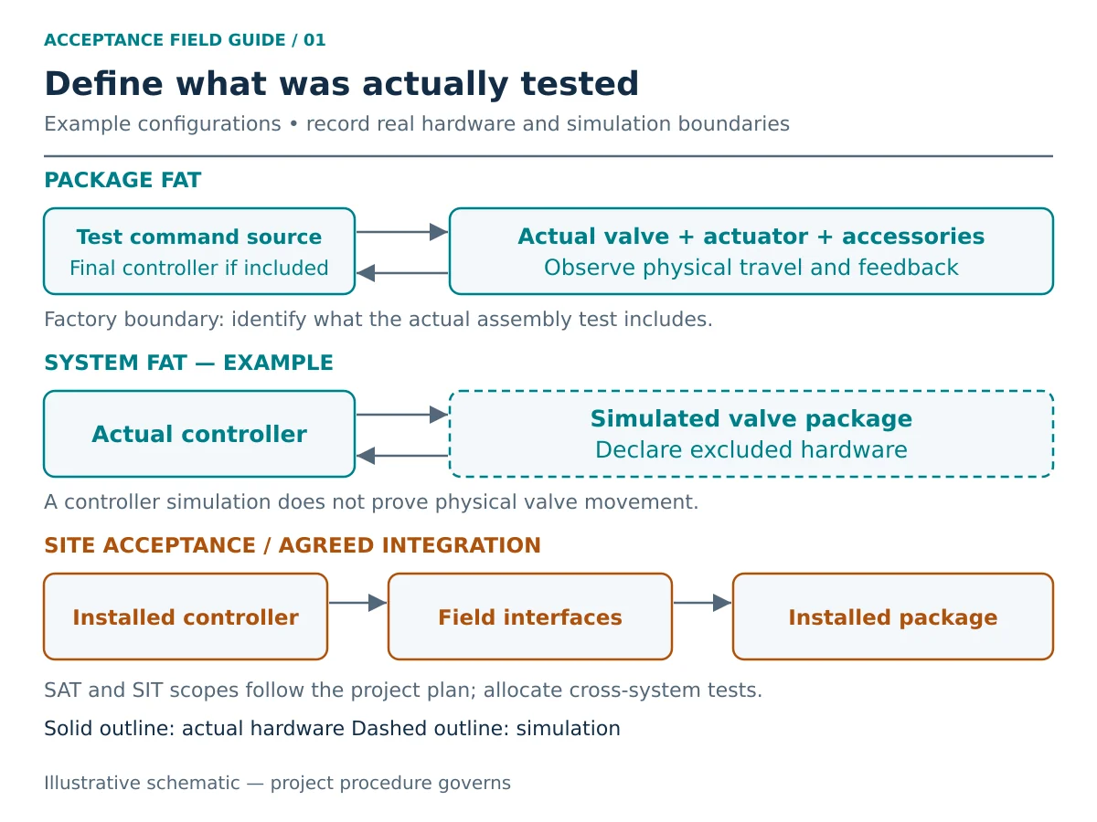
Package FAT, System FAT and Integration Boundaries
A package FAT may include the valve, actuator, mounting components, solenoid, position switches, positioner and local accessories. A control-system FAT may use a simulated valve instead. Neither description confirms that the actual valve and final controller were tested together.
Mark the tested boundary on the drawing: where the command enters, which hardware is real, which signals are simulated and where response is observed. Allocate untested interfaces to later checks.
IEC 62381:2024, edition 3, Automation systems in the process industry — Factory acceptance test (FAT), site acceptance test (SAT), and site integration test (SIT), provides a process-industry automation framework covering FAT, factory integration testing (FIT), SAT and site integration testing (SIT). Its published scope supports project-specific plans and agreed responsibilities. It does not establish universal valve-package stroke times or certify a supplied assembly.
Which Checks Should Be Repeated at Site?
Base repetition on the approved acceptance plan and what installation can change. Transport damage, removed accessories, reterminated cables, new air tubing and revised settings can affect previous results. A controller revision can also invalidate interface assumptions.
FAT and SAT are complementary acceptance stages, rather than alternatives selected solely by cost or location. Use FAT to close the requirements demonstrable within the agreed factory setup. Use SAT and the allocated integration tests to close installation-dependent and previously excluded interfaces. Neither stage, by its name alone, demonstrates every service-load or safety requirement.
Use a carry-forward register linking each FAT result to the site verification or justification for accepting that evidence unchanged. Functions deferred to site need an owner, procedure and closure point.
Decide What Factory Evidence Can Be Carried Forward
Use the following review to propose the site scope. The purchaser-approved test plan determines the final disposition; an unchanged assembly alone does not waive mandatory SAT or integration checks.
| Change or evidence gap | Proposed verification focus | Record needed before closure |
|---|---|---|
| No configuration change; complete tag-linked FAT evidence | Carry forward only the factory requirements accepted by the project; complete specified installation and interface checks. | Accepted FAT reference, receiving/installation checks and approved site scope. |
| Air tubing, regulator, exhaust or speed-control settings changed | Review affected timing, travel, utility-loss and restoration cases under documented installed conditions. | As-installed pneumatic revision, settings and linked results. |
| Cables reterminated, channels reassigned or controller logic revised | Review the affected command, feedback, mode, interlock, alarm and reset paths; identify necessary regression checks. | Current wiring/I/O and logic revisions, interface test cases and results. |
| Actuator, solenoid, switch or positioner replaced or adjusted | Review which original results depend on that component and repeat affected checks using the final configuration. | Component identity, change approval, revised baseline and retest links. |
| Test was unloaded or used simulated process/feedback signals | Identify which service-load or physical-interface requirements remain unproven; assign calculation, qualification or further testing as appropriate. | Explicit evidence gap, accepted verification method, responsible party and closure point. |
Each carried-forward result needs an evidence reference and authorized acceptance decision for the installed configuration.
Freeze the Test Basis Before Testing Starts
The test pack should identify the valve tag, valve and actuator models, accessory schedule, assembly drawing, wiring and pneumatic diagrams, firmware or configuration where relevant, and controlling document revisions. For integrated selection inputs, see actuated valve packages.
Record the service assumptions that limit the test: medium, design and operating temperature, operating differential pressure, seat construction, valve torque or thrust basis, minimum utility and required fail response. These inputs determine whether factory conditions represent the service case.
Differential pressure contributes to the load the assembly must overcome. Seat and packing friction can change the operating torque or thrust; supply pressure or voltage and accessory restrictions affect the available drive and response. Temperature and the test medium can also limit how representative an ambient factory stroke is. Record these conditions alongside each result. If the governing load data are missing, request the calculation or qualification basis rather than inferring actuator suitability from nominal size or pressure class.
An unloaded ambient stroke confirms operation under those conditions. It does not by itself prove operation against maximum differential pressure, cold-service friction or every specified temperature condition. Identify the calculation, qualification or additional test that supports those requirements.
For part-turn packages, ISO 5115:2023, Industrial valves — Part-turn valve actuation, addresses valve, actuator and mounting-kit design considerations, information responsibilities, selection and assembly. It is relevant to package review within that scope; it is not a universal FAT/SAT acceptance procedure, a basis for selecting an actuator from valve size alone or evidence of conformity for a supplied package.
Before witnessing, confirm:
- Each requirement has a measurable criterion and controlling reference.
- The assembly and document revisions match the test configuration.
- Real hardware, simulations, exclusions and deferred functions are listed.
- Instruments have suitable range, resolution and valid calibration where required.
- Witness/hold points, notification and release responsibilities are agreed.
- Test authorization, isolation and restoration controls are in place.
Unresolved acceptance values should be settled before the affected test. Successful movement alone is not an agreed pass criterion.
Witness and hold points: define their meanings in the approved ITP. A hold point generally requires release by the designated authority before the activity proceeds. A witness point requires the agreed notification and opportunity to attend; proceeding after non-attendance depends on the contract and approved waiver rules. State the notice period, responsible party, required evidence and release condition. An inspector’s presence does not replace the acceptance criterion or automatically close an open deviation.
Commands and Feedback: Verify the Complete Operating Path
Check Mode Selection and Command Priority
Define the required behavior in local, remote and any applicable automatic mode. State which commands are accepted, inhibited or overridden in each mode. Do not assume that every emergency demand overrides every selector position; verify the approved philosophy for the actual design.
For on/off duty, connect each command to actual travel and the corresponding indications. For modulating duty, specify the approved input points, direction, indicated travel and permitted deviation. Avoid assigning a generic accuracy tolerance to every positioner or package.
Contradictory commands and unavailable permissives require explicit expected results. A procedure should identify what is being challenged and how the result will be observed without relying on operator interpretation.
Separate Command Status, Position and Feedback
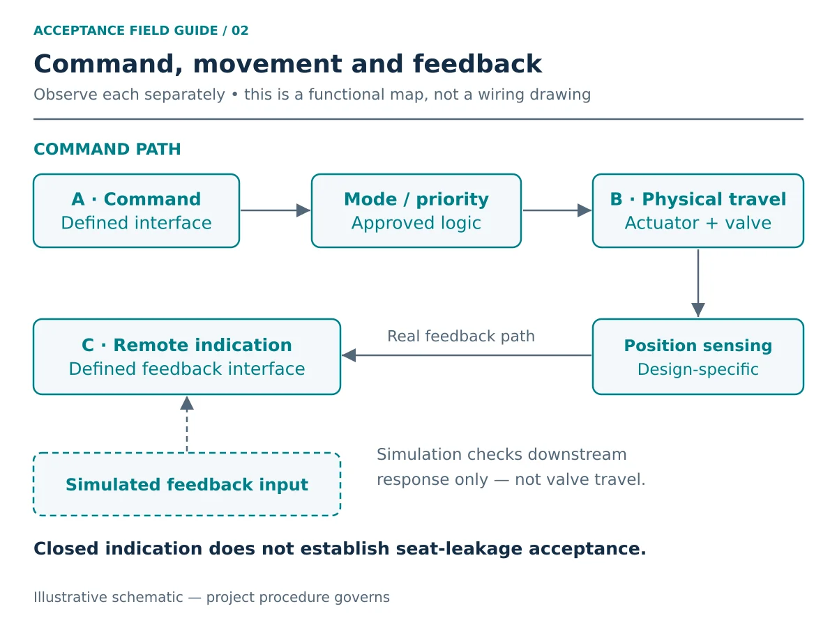
A command shown on a human-machine interface (HMI) proves that a request exists at that observation point. A feedback signal reports the state presented at the observation point; verification must establish the physical correspondence and integrity of the relevant signal path. Neither alone establishes every mechanical or sealing requirement.
Compare physical valve travel with local indication, switch operation and remote feedback as applicable. Record ambiguous states such as neither limit active, both limits active or command/position mismatch against the approved alarm philosophy. A closed limit is not a seat-leakage result.
The broader valve functional testing framework helps separate movement, indication and documented acceptance.
Illustrative commissioning scenario: an HMI reports “closed” before the observed valve travel reaches the approved terminal position. A switch setting, channel mapping or position indication may be inconsistent with the configuration. Compare independent travel observation, the switch actuation point and the I/O record under the approved test procedure; then correct the identified cause and repeat affected checks. Do not accept the HMI state as seat-leakage evidence.
Fail Action: Test Each Defined Failure and Recovery Case
“Fail close” is incomplete unless the initiating event is stated. Loss of instrument air, loss of electrical power, loss of control signal, solenoid valve (SOV) de-energization and a shutdown demand are distinct cases.
| Test case | Define before testing | الدليل المطلوب الاحتفاظ به |
|---|---|---|
| Instrument-air loss | Affected supply boundary, remaining power/signals and required final state | Initial position, supply condition, physical response and feedback |
| Electrical-power loss | Affected circuits and available pneumatic or stored energy | Which devices lost power and the resulting package response |
| Control-signal loss | Signal fault definition and configured fault response | Actual fault condition, position and diagnostics |
| Solenoid de-energization | Normal coil state and approved pneumatic routing | Coil state, valve response and indication |
| Shutdown demand | Demand source, command priority and required reset | Tested signal path, action, timing where required and reset behavior |
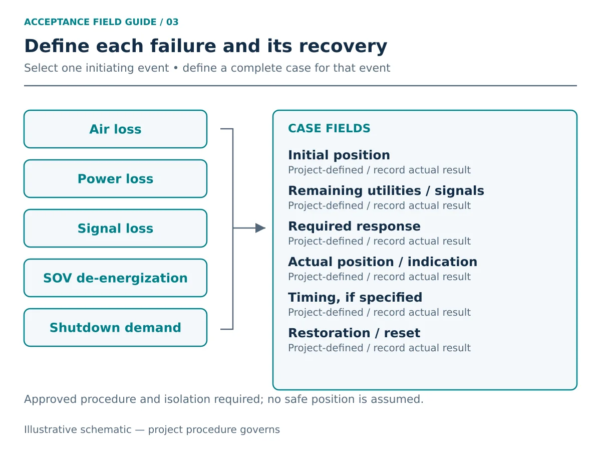
This matrix is a planning aid. Failure simulation must follow an approved procedure with appropriate isolation and authorization; it is not an instruction to disturb a running process.
Verify Final Position and Restoration Behavior
Record initial position, remaining utilities, expected response, actual final position and applicable timing. Where hold-position behavior is required, define the permitted movement and observation period. A double-acting actuator does not automatically establish a verified fail-in-place function.
For electric packages, establish whether the required action depends on batteries, capacitors, springs, UPS or another arrangement. State the stored-energy condition and any required reserve criterion.
Also define what happens when air, power or signal returns. The approved philosophy may require continued safe-state retention, manual reset or resumed control. Restoration is a separate acceptance step because unexpected restart can occur even after correct initial fail movement.
Illustrative restoration scenario: a package reaches its required position during a specified power-loss case, then moves when power returns because an outstanding command is accepted. Check the released command, mode, latch and reset philosophy before assigning the cause. Resolve any mismatch through approved configuration review and repeat the recovery case; the initial fail movement alone does not complete acceptance.
Interlocks and Trips: Verify Logic and Physical Response
Permissives allow an action; interlocks constrain or initiate actions according to defined conditions; trips drive a specified shutdown response. Alarms and reset functions need their own expected outcomes. Use project terminology consistently.
Map Every Case to the Cause-and-Effect
Identify the initiating condition, affected outputs, relevant modes, expected valve response, indication, alarm and reset requirement. Where voting, delays or latching apply, reference the released logic.
Example case structure: cause-and-effect row ID → stated operating mode → defined trip input → project-required valve response → expected feedback/alarm → specified reset/restoration condition. Record both expected and actual outcomes, the tested interfaces and any simulation. Every value and command priority comes from the approved project documents.
A simulated input can verify downstream logic within the tested boundary. It cannot prove an excluded field sensor, final wiring or every installed interface. Likewise, a simulated “valve closed” input does not prove physical closure.
Identify Site Integration Work
Maintain a list of functions requiring the real controller, package, field inputs or other systems to operate together. Project SAT and SIT scopes may divide this work differently; preserve the requirement-to-test mapping regardless of the label used.
Test controls should account for temporary simulations or authorized overrides, their removal and the final restored state. This article does not prescribe bypassing protective functions. Safety-function validation requires its own applicable lifecycle evidence and approved plan.
Stroke Time: Define the Clock Before Setting the Limit
“The valve closes in five seconds” is not an acceptance statement unless the measurement endpoints and conditions are defined. No universal time limit is proposed here.
Separate Three Timing Quantities
| الكمية | Example timing boundary | What it establishes |
|---|---|---|
| Mechanical travel time | Defined start of physical movement to defined terminal travel | Movement duration under the recorded conditions |
| Command-to-feedback time | Command at a specified interface to valid terminal feedback at a specified interface | Measured interval between the specified command event and valid feedback event at the defined interfaces |
| Safety-function response time | Initiating event to required safe state, as defined in the safety requirements | Performance of the included safety-function chain |
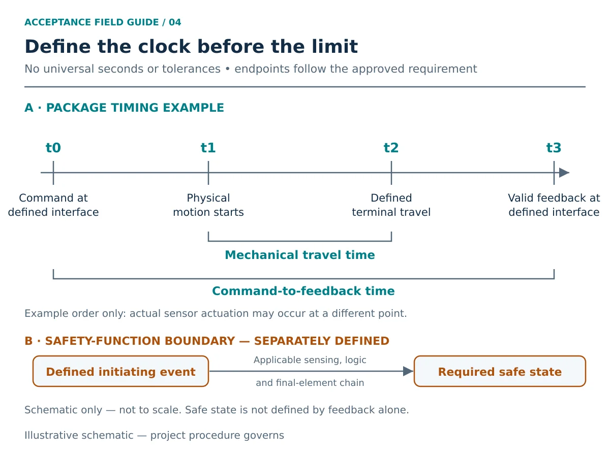
A position sensor can change state before the valve reaches its physical terminal travel. Define its actuation point and the required observation of actual travel; a feedback event alone does not establish full terminal travel, seat tightness or the process-safe state.
Record opening and closing separately. Normal powered operation and fail-action travel can have different driving energy, restrictions and timing. A fast normal close does not establish an acceptable failure response.
For the actual supplied configuration, use the applicable equipment instructions and safety manual together with the approved project criteria. These documents define the required observation and response-time verification; a generic example does not establish the package’s safe state, required time or certification.
Write a Complete Timing Acceptance Line
Use this specification pattern: tag + direction/event + initial position + start/end interfaces + supply/load conditions + permitted time range + repetitions + measurement method + controlling revision. Assign the values from approved project requirements.
If one report times from coil de-energization to physical terminal travel while another times from the control-system demand to remote closed feedback, the values describe different intervals. Align the endpoints before judging a difference. Where results are close to a limit, apply the approved measurement uncertainty and decision rule; do not round a value into compliance.
Record Conditions That Affect the Result
For pneumatic packages, document supply conditions at the relevant interface, pressure during movement where required, regulator settings and relevant tubing, exhaust and speed-control configuration. For electric packages, document supply voltage, selected speed or control settings and duty limitations as applicable.
For either route, identify initial/final positions, loading or differential pressure, test medium, temperature, measurement method and required repetitions. Define any minimum as well as maximum time: faster movement can introduce unacceptable transient effects in some services.
Investigate Differences Before Adjustment
Illustrative timing scenario, not an actual project result: a package passes factory timing but exceeds the agreed site limit. The factory used short supply tubing and no process differential pressure; the site setup may introduce supply droop, exhaust restrictions, a changed load or different timing endpoints. Compare the recorded factory and site conditions, observe utilities at the defined interface and verify the measurement boundary before assigning a cause or approving adjustment.
An adjustment that improves time can affect other requirements. Apply approved change control and repeat affected checks, including fail behavior where relevant. Reconcile a timing limit that lacks a defensible service basis instead of tuning solely to obtain a pass.
Acceptance Records: Make Every Result Traceable to a Tag
A checked box is weak evidence when the configuration, criterion or actual result is missing. Connect the record to the supplied assembly and the requirement being accepted. See inspection and test planning for the wider evidence route.
Minimum Record Fields
| Record group | Fields to include |
|---|---|
| Identity | Project, PO, tag, serial numbers and relevant component identifiers |
| خط الأساس | Procedure revision, drawings, logic/configuration and applicable requirement |
| Setup | Utilities, load, medium, instruments and calibration references |
| Test case | Initial condition, initiating event, simulation boundary and expected result |
| Result | Actual measured/observed result, units, evidence reference and pass/fail disposition |
| Exceptions | Deviation / nonconformance report (NCR), corrective action, approval and linked retest |
| Closure | Witness/date, open items, release limitations and authorized signatures |
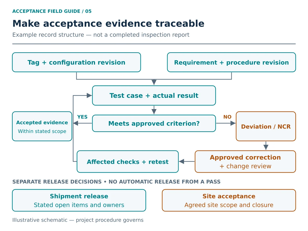
The approved procedure should define sampling, timing resolution and supporting evidence. Screenshots or videos can supplement records where appropriate; they do not replace a clear measured result and acceptance basis.
Configuration records also matter. Rotork’s CVA commissioning report documentation illustrates retaining actuator configuration with valve and site details for that product. Request an equivalent traceable record appropriate to the equipment actually supplied.
Example of a Tag-Linked Acceptance Record
Illustrative record structure, not a completed report: the fields below show how a normal-command or fail-action case can remain auditable without inventing measured data.
| الميدان | Required entry |
|---|---|
| Requirement and case identity | Actual valve tag; requirement ID; test-case ID; FAT/SAT stage and declared boundary. |
| Initiating condition | Specified command or failure event; initial position; operating mode; utilities and signals that remain available. |
| Controlling documents | Approved procedure, fail-action schedule, drawing and logic/configuration revisions applicable to this case. |
| Expected outcome and criterion | Required physical response, indication, alarm and restoration/reset; approved timing endpoints and limits if applicable. |
| Actual evidence | Observed movement, final position and indication; measured time and conditions where required; instrument and supporting-record references. |
| Disposition and closure | Pass/fail against the cited criterion; deviation and correction references; affected-check review; retest; required witness and acceptance signatures. |
Missing criteria or results remain open items requiring an agreed disposition; a “pass” tick cannot close them.
Separate Shipment Release from Site Acceptance
Preserve original failed results and the final configuration baseline. The change review determines whether regression checks extend beyond the failed case.
A shipment release may allow specified site activities to remain open. It should identify those items, their owners and contractual disposition. Site acceptance should address installation changes, deferred tests and punch-item closure within the agreed acceptance scope. Neither signature automatically authorizes startup or completes every commissioning obligation.
Illustrative records scenario: a tag-linked FAT report records a pass, but the site actuator settings have a later revision and no change record. The earlier result may no longer cover the installed baseline. Reconcile the as-tested and as-installed revisions, identify affected functions, obtain the authorized disposition and retain the required retest evidence before closing the relevant acceptance item.
RFQ Checklist: Agree the FAT/SAT Scope Before Purchase
Ask bidders to identify:
- Complete valve, actuator, accessory and documentation scope.
- Torque/thrust and service-load basis, operating cases and minimum utility.
- Command interfaces, feedback, fail scenarios, restoration and reset requirements.
- Timing endpoints, limits, test loading and required repetitions.
- Real versus simulated controller and field interfaces.
- FAT, site testing and integration responsibilities, including site-support inclusions.
- Witness/hold points, notification, instruments and required records.
- Exclusions, deviations, retest responsibility and release conditions.
This makes quotations comparable and exposes site work that might otherwise be omitted. Valve size and pressure class alone cannot establish actuator suitability or complete package acceptance.
Normalize the Supplier Test Scope
For each bidder, ask for a stated inclusion, exclusion or deviation against the same scope lines:
| Scope line | Question for the bidder |
|---|---|
| Factory assembly and interfaces | Will the final valve, actuator and listed accessories be tested together? Which command and feedback interfaces are real or simulated? |
| Utilities and test load | What supply range and load will be demonstrated? Which service cases rely on separate calculations or qualification evidence? |
| Site and integration work | Who supplies personnel, controller access, test equipment and approved procedures? Which SAT/SIT functions are outside the offer? |
| Witness, changes and retests | What notification and witness points are included? How are corrections, repeat attendance and additional testing handled contractually? |
| Final dossier and release | Which tag-linked results, configuration records and open-item registers are included? Who authorizes shipment and site acceptance? |
Resolve scope differences before comparing prices. A factory-only offer and an offer including installed-system checks carry different responsibilities, even if both use the phrase “FAT/SAT included.”
Sources and Application Limits
- IEC 62381:2024, edition 3 — official publication scope: a process-industry automation acceptance framework. Select the contract-approved edition and project procedure; its general scope does not assign valve-specific stroke times or certify the assembly.
- ISO 5115:2023, edition 1 — Industrial valves — Part-turn valve actuation: official scope checked for the part-turn package discussion above. It does not establish order-specific performance or a universal site acceptance method.
- Rotork — CVA commissioning report: a product-specific configuration-record example. Its historical software details are not a recommendation to install the tool or a requirement for other actuators.
These references support their stated topics. They do not demonstrate Raymon Valve product certification, completed testing or a particular service capability.
أسئلة متكررة
What Is the Difference Between Package FAT and System FAT?
Package FAT tests the actual assembly within its defined boundary. A system FAT tests control-system functions and may represent the valve with simulation. Identify whether the actual package and controller were connected and which interfaces remain untested. Which FAT Checks Should Be Repeated During SAT?
Repeat checks required by the approved plan and those affected by transport, installation, retermination or configuration changes. Document which factory evidence is carried forward and why. Can Simulated Feedback Prove That the Valve Physically Moved?
No. It can establish downstream response to that simulated signal. Physical travel and the real feedback path need their own verification. Should Air, Power and Signal Failure Be Tested Separately?
Treat them as separate specified scenarios. The package can respond differently depending on which devices lose energy or signal and what remains available. How Should Stroke-Time Acceptance Be Specified?
Define direction, initiating event, start/end observation points, utilities, load, measurement method and permitted range. Specify normal and fail-action cases separately where needed. Does Closed Feedback Prove Seat Tightness?
No. It does not establish allowable leakage under a defined pressure, medium and duration. Define pressure and seat-leakage testing separately, with the applicable procedure, acceptance criterion and tag-linked record. Does FAT Replace SAT or Safety-Function Validation?
No automatic substitution applies. The project must map each requirement to appropriate evidence. A package FAT does not establish excluded installed interfaces or complete safety-function validation. Which Records Close an Acceptance Deviation?
Retain the original result, identified cause where established, approved corrective action, configuration changes, affected-function review and successful retest evidence, with the required disposition and signatures.
Request ITP and Documentation List
To start a testing-scope review, send your tag list or package datasheet, command/feedback interfaces, defined fail-action cases, timing criteria and witness/documentation requirements. Identify unresolved fields explicitly.
For a service-load or actuator-suitability review, also include the medium, pressure-temperature cases, operating differential pressure, valve torque/thrust basis and utility limits. Attach available wiring/pneumatic drawings and cause-and-effect documents so factory, site and integration responsibilities can be distinguished in the proposed scope.
Request ITP and Documentation List
Final supplied scope, acceptance and suitability depend on the approved order documents and tag-specific evidence. This guidance does not establish completed testing, certification or guaranteed performance for a supplied package.
Publication Responsibility and Engineering Scope
Publisher: Raymon Valve. This article supports specification, procurement and acceptance-scope planning. Its example matrices and diagrams are explanatory tools, not completed FAT/SAT records or order-specific engineering approval.
The responsible project team must confirm the safe state, load capability, timing criteria, procedures and release authority against approved documents. Pressure-boundary, seat-leakage, material, special-test and safety-function requirements retain their own evidence and acceptance scope.
 Arabic
 English
 German
 French
 Spanish
 Italian
 Portuguese
 Russian