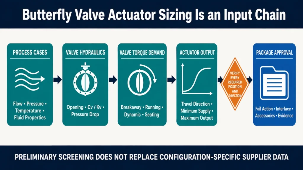
Butterfly valve actuator sizing requires more than valve size and nominal pressure class. Engineers must compare the valve's torque demand throughout travel with the actuator's available output in both directions and at the minimum available supply. That review needs the actual flow cases, fluid properties, differential pressure, valve opening, manufacturer Cv/Kv data, seat and bearing configuration, fail action and accessory scope. Preliminary calculations can screen a proposal, but final approval requires configuration-specific data from the valve and actuator suppliers.
Límite de ingeniería: This is an input-validation framework, not a sizing calculator. It does not assign a valve size, Cv/Kv, torque, safety factor or actuator model.
Start With Operating Cases, Not an Actuator Catalog
An actuator cannot be reviewed against one nominal condition. The load on a butterfly-valve disc can change between the closed position, intermediate travel and the fully open position. The actuator output can also change through its stroke, particularly with a spring-return mechanism.
Define the cases the package must complete before comparing torque values:
- opening after the maximum expected idle period;
- closing against the maximum shutoff differential pressure;
- travel at minimum, normal and maximum flow;
- startup, shutdown and credible upset conditions;
- emergency or fail-action travel after loss of power, air or control signal;
- modulating operation at the expected range of disc positions;
- reverse flow or pressure direction, when the valve is expected to operate in both directions.
Each case needs a source and an owner. A process datasheet may define flow, pressure and temperature. The valve manufacturer should define torque demand and allowable mechanical loads for the offered construction. The actuator manufacturer should define output at the stated supply and spring configuration. The project engineer should approve the failure response and operating envelope.
Quick Input-Validation Matrix
| Review block | Required inputs | Evidencia a solicitar | Pregunta de aprobación |
|---|---|---|---|
| Proceso | Flow, pressure, temperature, phase and fluid properties | Approved operating cases | Are all controlling cases represented? |
| Valve hydraulics | Cv/Kv by opening and pressure-drop basis | Model-specific curve or table | Does the hydraulic data match the quoted valve? |
| Valve torque | Required torque by travel and direction | Configuration-specific torque data | Where does the maximum required torque occur? |
| Actuador | Output by travel and direction | Output curve at the stated supply | Is sufficient output available at every required position? |
| Failure response | Fail action and utility-loss conditions | Control narrative and accessory schedule | Can the package reach the required safe state? |
| Mechanical limit | Allowable shaft, coupling and gearbox loads | Manufacturer limits | Can maximum actuator output damage the assembly? |
Define the Flow and Fluid Inputs
Flow affects more than nominal capacity. It contributes to the velocity and pressure distribution around the disc, which can change the hydrodynamic load during travel. The review should include minimum, normal and maximum flow rather than one design value.
For liquids, collect flow rate, density or specific gravity, viscosity, operating temperature, upstream and downstream pressure, and vapor pressure when cavitation or flashing must be reviewed. Record solids, particle size and phase condition when deposits, erosion or blockage could affect the seat or disc.
For gases and vapors, record whether flow is stated as mass flow, actual volumetric flow or standard volumetric flow. The calculation owner may also require absolute pressures, temperature, molecular weight or specific gravity, compressibility data and other thermodynamic inputs. A gas-service conclusion should not be produced from a liquid shortcut.
Operating cases must be internally consistent. A maximum flow case should use the pressures and temperature that occur with that flow, not values copied from unrelated design limits. Design pressure and temperature remain important mechanical boundaries, but they are not automatically the hydraulic conditions that govern actuator load.
Normalize Liquid and Gas Operating Cases Before Calculation
The calculation owner should receive one internally consistent row for each operating case. Do not combine maximum flow from one case with pressure or temperature limits from another.
| Input group | Liquid service | Gas or vapor service | Why the distinction matters |
|---|---|---|---|
| Flow basis | Actual volumetric flow at the stated condition | Mass flow, actual volume or standard volume with the reference basis stated | Mixing bases can invalidate velocity and capacity comparisons. |
| Fluid properties | Density or specific gravity, viscosity and vapor pressure where relevant | Molecular weight or specific gravity, compressibility data and thermodynamic basis where required | The required method and intermediate checks differ by phase. |
| Pressure record | Upstream and downstream pressure for the same flow and temperature case | Absolute upstream and downstream pressure where the selected gas method requires it | Differential pressure alone may not define a gas-flow case. |
| Additional review flags | Cavitation, flashing, solids, fouling or erosion risk | Choked-flow, noise, condensation or two-phase risk where applicable | These flags can change the calculation route and required evidence. |
Pipeline Velocity and Local Velocity Around the Disc Are Different
Pipeline-average velocity is derived from the flow rate and the internal flow area of the pipe. It is useful for system screening, but it does not describe every local condition inside a partially open butterfly valve.
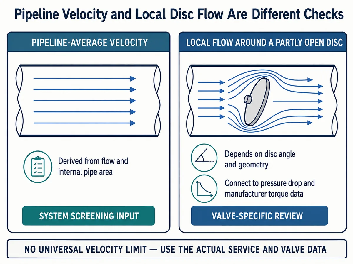
The disc occupies part of the passage even when the valve is open. At an intermediate angle, the available flow area and pressure distribution depend on the disc profile, shaft position, valve bore, opening angle, flow direction and nearby piping. Flow can accelerate locally around the disc, and the resulting forces can create a torque on the shaft.
This is why a universal pipeline-velocity limit cannot determine actuator size. Velocity must be evaluated with the valve geometry, pressure drop at the relevant opening and the manufacturer's hydrodynamic or dynamic-torque data. Reducers, elbows or other disturbances near the valve may also change the installed condition and should be identified for engineering review.
Separate Fully Open Loss, Throttling Pressure Drop and Shutoff Differential
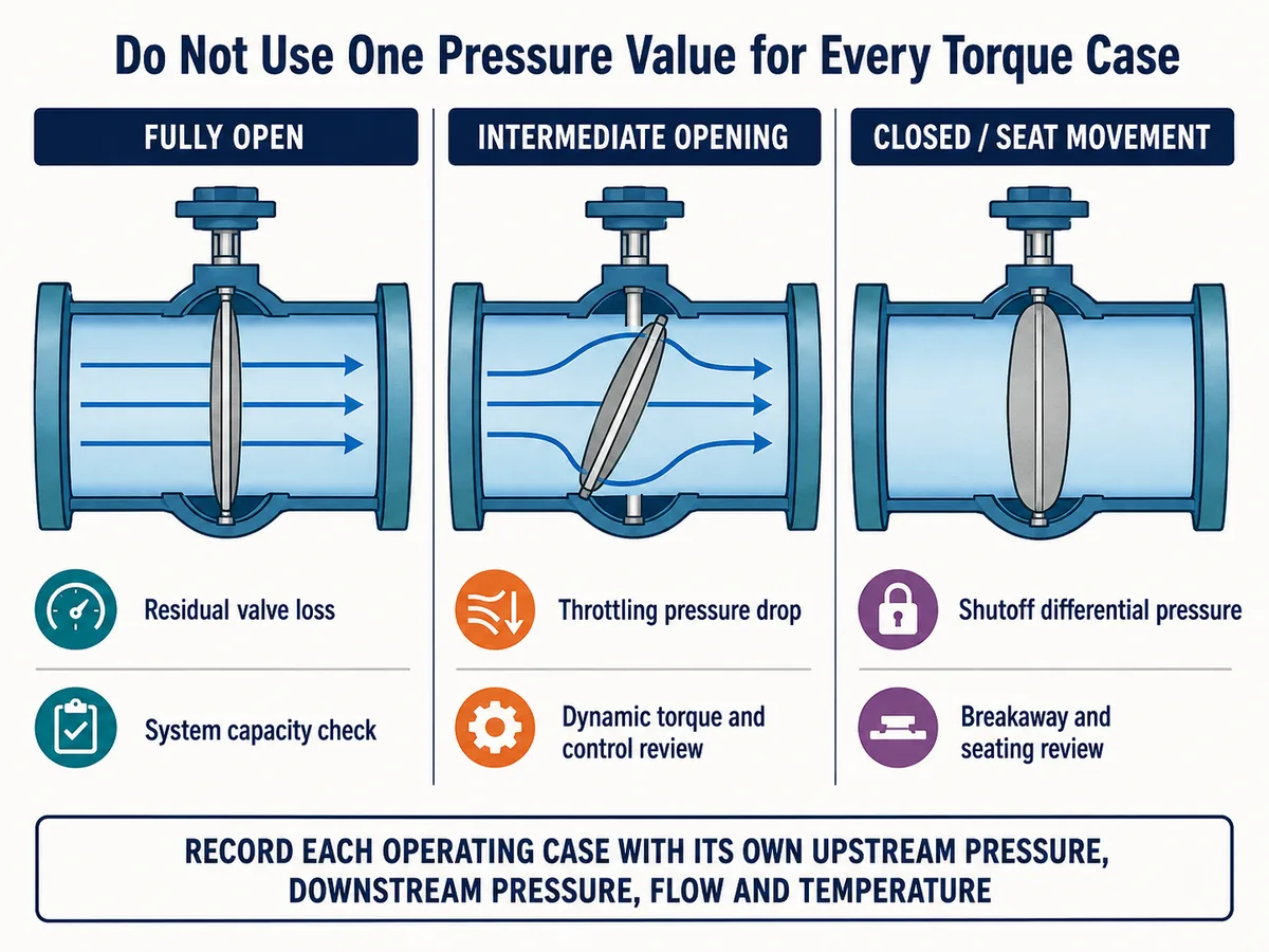
“Pressure drop” can refer to different conditions that should not be mixed.
Fully open pressure loss is the residual hydraulic loss when the disc is near its open position. This matters for system capacity and pumping or compression duty.
Throttling pressure drop is the difference across the valve at an intermediate opening. It changes with the system operating point and is relevant to flow capacity, local velocity, noise, cavitation or erosion risk, and dynamic torque.
Shutoff differential pressure is the pressure difference the valve must hold or move against near the closed position. It can govern break-to-open, unseating or seating load even when there is no flowing condition through the closed valve.
The actuator review should therefore identify the pressure differential at break-to-open, through travel, at the expected modulating positions, during fail action and in any reverse-pressure case. Using the pipeline design pressure as a substitute for all these cases can either understate the real load or produce an uneconomic package.
Use Cv/Kv Data for the Actual Valve and Opening
Cv and Kv describe flow capacity under defined reference conditions and units. They do not describe actuator torque. However, they help connect the required flow, available pressure drop and valve position.
A full-open Cv/Kv value is not enough for modulating duty. Butterfly-valve flow capacity changes with opening angle, and the relationship depends on the manufacturer's valve style and geometry. Published data from one valve series should not be transferred to another valve merely because the nominal size is the same.
Request the following from the valve supplier:
- exact valve series, size and construction;
- disc and seat configuration;
- Cv or Kv at relevant opening positions;
- the opening-angle convention used in the table or curve;
- flow direction and test or calculation basis;
- applicable fluid or flow-regime limitations;
- any correction needed for reducers or installed piping.
For modulating service, the selected calculation method and installed flow characteristic require a separate control review. The article does not assign a final Cv/Kv, valve size or operating angle without the actual process cases and product data.
Treat Valve Torque as a Profile Through Travel
A single catalog torque value may not represent every load the actuator must overcome. The required review should distinguish the following torque cases.
Break-to-Open and Unseating Torque
This is the load required to initiate movement from the closed position. It can be affected by seat friction, differential pressure, temperature, time in the closed position, deposits and the exact sealing construction.
Running Torque
Running torque includes the mechanical resistance encountered during travel, including applicable bearing, shaft-seal and packing friction. It should be evaluated in both directions where the load is not symmetrical.
Dynamic Torque
Flowing fluid creates forces on the disc. The resulting dynamic torque can change with disc angle, differential pressure at that angle, valve size, disc geometry and flow direction. A manufacturer may publish product-specific coefficients or torque curves for this purpose. Those data belong only to the identified valve design and conditions.
Seating and End-to-Close Torque
The actuator must complete final seat engagement without stalling. Required seating torque should not be replaced by a mid-stroke running value.
The review also needs the maximum allowable shaft, key, coupling, gearbox and stop loads. More actuator output is not automatically safer: excessive output or an incorrect torque-switch setting can overload the valve drivetrain.
On-Off Isolation and Modulating Duty Require Different Checks
For on-off isolation, the main cases normally include breakaway, full travel, seating, maximum shutoff differential pressure, required travel time and the specified fail action. The valve may spend most of its time fully open or fully closed, but infrequent operation and deposits can influence the next breakaway event.
Modulating service adds another set of questions. The valve may remain at an intermediate angle where pressure drop and dynamic torque are significant. The review should cover the expected operating range, Cv/Kv versus opening, installed flow characteristic, positioner performance, control signal, stability and potential cavitation, noise or erosion.
Do not convert an isolation-valve selection into a control-valve recommendation merely because a butterfly valve can be positioned between open and closed. The control objective, process dynamics and product-specific performance must support that duty.
Match Valve Demand to Actuator Output at Every Required Position
The valve torque profile and the actuator output profile must use compatible positions and directions. Check the package at break-to-open, run-to-open, end-to-open, break-to-close, run-to-close and end-to-close as applicable.
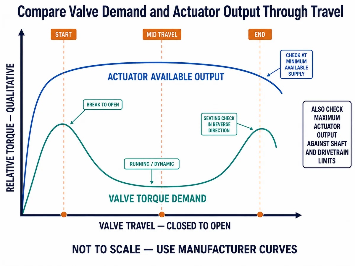
For pneumatic or hydraulic actuators, use the confirmed minimum supply available when the valve must move. Do not size from a favorable catalog pressure if the plant cannot guarantee it at the actuator inlet under the governing condition. Also check the maximum possible supply because it may produce output above the allowable valve or drivetrain load.
For spring-return actuators, the powered stroke and spring stroke have different output profiles. The selected spring set, mounting orientation and fail direction must be included. A fail-closed package must have adequate closing output under its specified loss condition; a fail-open package must be evaluated in the opposite direction.
For electric actuators, confirm available voltage and frequency, running and seating torque settings, duty cycle, starts per hour, speed, ambient derating, loss-of-power behavior and mechanical output limits. The actuator nameplate or maximum output alone does not close these checks.
Include Fail Action and Accessories in the Package Review
The required safe state must be stated as fail closed, fail open or fail in place. The project should also define what “failure” means: loss of electrical power, loss of air or hydraulic pressure, loss of control signal, solenoid failure or another specified event.
Accessories can affect whether the package performs the required function. Define the positioner, solenoid valve, limit switches, feedback, manual override, speed controls, booster or volume tank, mounting kit, coupling and local indication where applicable. Visible accessories in a photograph or sample configuration do not establish the included order scope.
Required travel time should be reviewed with the process consequences. Faster movement is not universally better, particularly where system transients are a concern. Final timing belongs to the system and controls review.
Separate Manufacturer Data From Project Assumptions
The valve manufacturer should supply torque data and mechanical limits for the quoted configuration, including the basis for differential pressure, temperature, pressure direction, seat, bearings and packing. The same supplier should identify the applicable Cv/Kv data and opening convention.
The actuator manufacturer should supply output through travel for the selected actuator, supply condition and spring configuration, together with environmental and duty limitations.
The project owns the approved process cases, failure consequence, safe state, utilities, control philosophy, travel time and documentation requirements. If any of these inputs remain assumptions, record them explicitly and assign a responsible owner and closeout document.
Normalize the Technical Bid Against the Same Control Points
A quotation should be evaluated against the project cases, not only against the supplier's selected catalog row. Keep a hold open whenever the offered data cannot be traced to the quoted configuration.
| Control point | Project record | Supplier return | Hold final approval when |
|---|---|---|---|
| Hydraulic case | Tag-linked flow, upstream pressure, downstream pressure, temperature and phase | Calculation case using the same conditions | Values are copied from unrelated design limits or another operating case. |
| Cv/Kv by opening | Required operating range and control duty | Curve or table for the exact valve series, size and opening convention | Only a full-open value or a different valve series is supplied. |
| Valve torque demand | Opening, closing, fail and reverse-direction cases | Breakaway, running, dynamic and seating demand with assumptions identified | A single torque number has no position, direction, pressure or configuration basis. |
| Actuator available output | Minimum and maximum available utility supply | Output through travel for the selected mechanism and spring set | Output is stated only at a favorable nominal supply. |
| Mechanical protection | Valve and drivetrain configuration | Allowable shaft, coupling and gearbox loads plus actuator maximum output | Oversizing or torque settings could exceed an allowable component load. |
| Failure and accessories | Defined failure event, safe state, travel time and control narrative | Fail action, mounting, solenoid, positioner, switches, override and timing basis | The package cannot be traced to the required failure response or accessory scope. |
Butterfly Valve Actuator Sizing Checklist
Before approving a quotation, confirm:
- Valve size, design, pressure class, seat, disc, shaft, bearings and flow direction.
- Minimum, normal, maximum, startup, shutdown and fail-action process cases.
- Medium composition, phase, density, viscosity, temperature and relevant gas properties.
- Upstream and downstream pressure for each hydraulic case.
- Maximum shutoff differential pressure and its direction.
- Cv/Kv versus opening for the offered valve configuration.
- Break-to-open, running, dynamic and seating torque by position and direction.
- Maximum allowable shaft and drivetrain torque.
- Actuator output throughout travel at minimum and maximum available supply.
- Double-acting or spring-return configuration and required fail action.
- Positioner, solenoid, switches, feedback, override and other accessory scope.
- Required travel time, operating frequency and duty cycle.
- Mounting, coupling, orientation and available installation clearance.
- Calculation, drawing, functional-test and deviation documents required for approval.
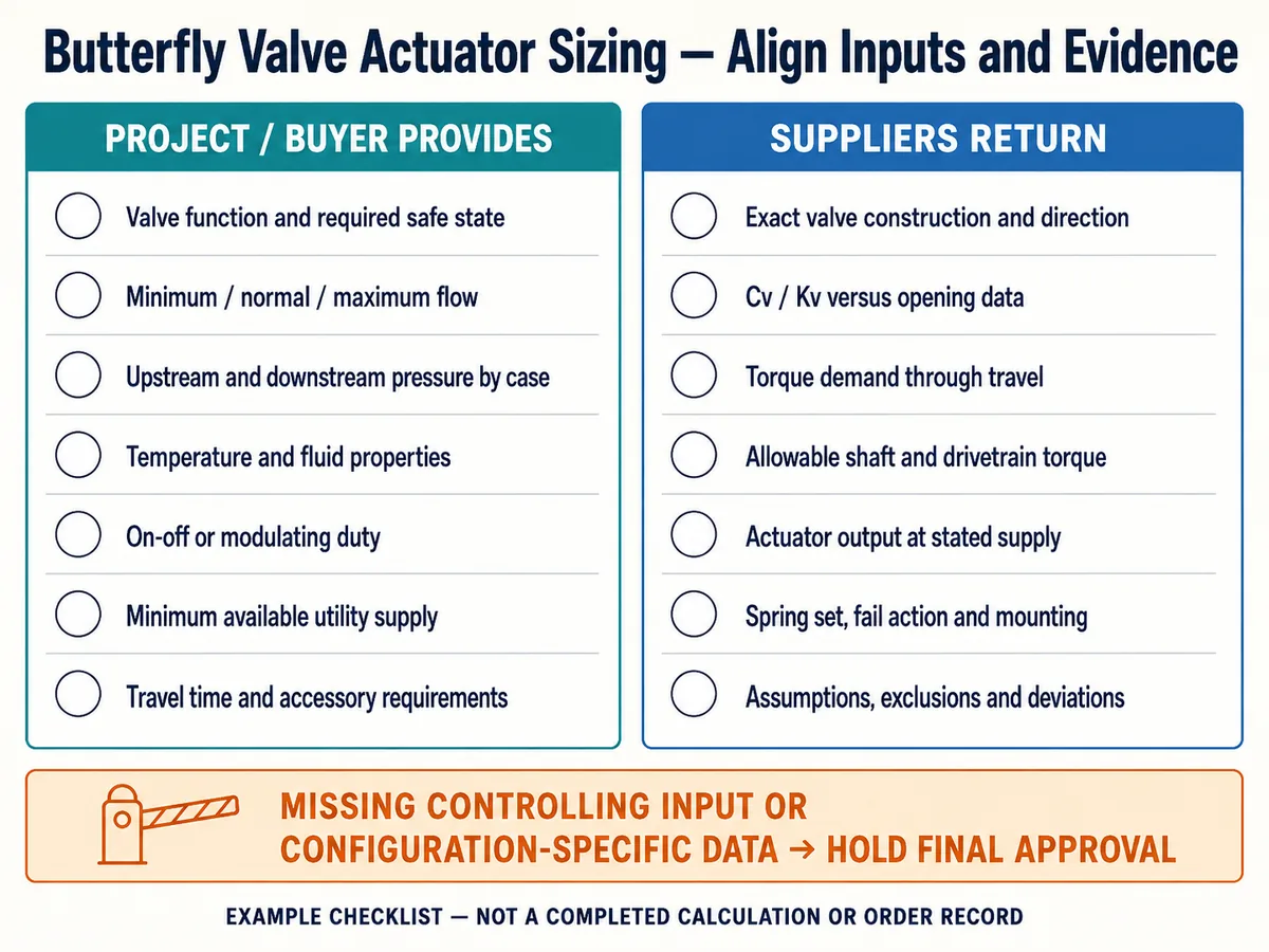
Preliminary Screening Is Not Final Approval
A preliminary review can identify missing inputs, compare possible actuation routes and detect an obvious mismatch between valve demand and actuator output. It can also produce a focused clarification list for the RFQ.
Final approval requires the approved process cases, exact valve configuration, manufacturer-issued torque and Cv/Kv data, selected actuator output curves, fail-action confirmation, interface drawings and package test requirements. The accepted calculation and documents should identify the valve tag, model, revision and applicable operating cases.
Request a Butterfly Valve Actuator Torque Review
Send the valve size and construction, medium, minimum/normal/maximum flow, upstream and downstream pressure, operating temperature, maximum shutoff differential pressure, duty, fail action, available utility supply, travel time and accessory requirements. Include the supplier torque and Cv/Kv sheets when available.
Raymon Valve can use those inputs to support a project-specific technical review. Final valve and actuator approval remains subject to the accepted supplier data, project requirements and responsible engineering review.
Method and Evidence Sources
- Bray resilient-seated butterfly valve technical manual — illustrates that torque components and Cv/Kv data are tied to a named valve construction and opening condition.
- Bray Series 3-Cx technical sales manual — provides a manufacturer-specific example of dynamic-torque factors and valve sizing coefficients by opening.
- Emerson FieldQ actuator data sheet — illustrates output variation with supply, stroke direction and spring configuration, together with maximum stem-torque checks.
- ISA75.01 committee scope — identifies the control-valve sizing-equation context for compressible and incompressible fluids.
Use boundary: These sources support the review method only. Their numerical values, recommended openings, service classes, margins and product conclusions do not transfer to a Raymon Valve configuration or a project tag.
Preguntas frecuentes
Can an actuator be sized from butterfly-valve diameter alone?
No. Diameter does not define the seat friction, differential pressure, disc geometry, flow load, operating direction, supply pressure or fail action. The exact valve torque and actuator output data are required.
Which torque value controls actuator sizing?
There is no universal controlling value. The maximum required load may occur at breakaway, during travel or at seating, depending on the valve construction and operating case. Compare the complete valve-demand and actuator-output profiles.
How does pressure drop affect butterfly-valve torque?
Pressure distribution across a partially open disc can create dynamic torque. The relationship depends on opening angle and the manufacturer's valve geometry, so product-specific coefficients or curves are needed.
Is full-open Cv enough for actuator sizing?
No. Cv/Kv describes flow capacity, not torque, and the full-open value does not describe intermediate positions. Modulating duty requires Cv/Kv by opening together with the relevant pressure-drop and torque data.
Why use minimum actuator supply pressure?
The actuator must provide adequate output when the available air or hydraulic supply is at its confirmed minimum. A catalog output based on a higher pressure may overstate what is available in service.
What actuator safety factor should be used?
This article does not prescribe a universal percentage. The margin should follow the project requirement and the valve and actuator suppliers' approved methods, while accounting for known service variability. A margin cannot replace missing process or torque data.
Is sizing different for on-off and modulating butterfly valves?
Yes. Modulating service requires review of the active opening range, Cv/Kv characteristic, changing pressure drop, dynamic torque and control performance. On-off duty still requires breakaway, travel, seating and fail-action checks.
What documents should suppliers provide?
Request configuration-specific valve torque and Cv/Kv data, actuator output curves, supply and spring basis, mechanical limits, mounting information, sizing calculations, accessory schedule, interface drawings and package functional-test requirements.
