
An extended bonnet separates a cryogenic valve’s cold body from its stem-packing chamber, but no universal bonnet length guarantees the required packing temperature. Selection begins with the applicable standard’s dimensional reference, the packing system’s qualified temperature range, the actual insulation boundary and the permitted valve orientation. Engineers then review heat-transfer assumptions, cold-box or piping clearances, and test evidence covering the proposed configuration. The following drawing-review and RFQ checks help engineering and procurement teams identify missing design information before technical approval.
1. Extended Bonnet Design: What Must Be Verified First?
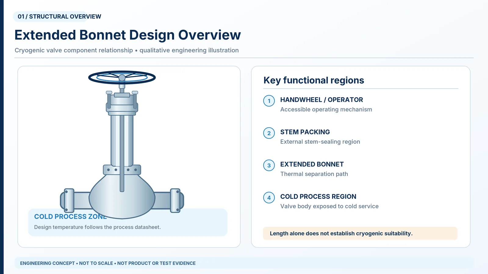
Cryogenic valves may operate at process temperatures far below the acceptable operating range of some stem-packing assemblies, actuators or accessible mechanical components. An extended bonnet creates additional distance between the cold body and the packing chamber. In an appropriate configuration, this region supports a controlled temperature transition between the process and the surroundings.
The purpose is not simply to increase overall valve height. It is to keep the sealing system within its qualified operating envelope while satisfying installation, operating and maintenance requirements.
Quick selection answer: First confirm whether the project uses a non-cold-box vapour-column reference or a cold-box extension reference; then check the corresponding controlled-standard dimension for the applicable valve type, size and temperature case. Before approving the drawing, reconcile the packing qualification, insulation boundary, permitted orientation, maintenance access and qualification evidence. If a required datum or acceptance basis is missing, return the bid for clarification rather than selecting a length by overall height.
Five Design Inputs That Control Bonnet Selection
| Design input | Pregunta de ingeniería | Required verification |
|---|---|---|
| Temperatura mínima de diseño | What is the lowest credible process temperature, including transients? | Approved process datasheet |
| Sistema de empaquetadura | What conditions can the complete sealing assembly tolerate? | Packing specification and qualification data |
| Extension geometry | What separates the packing chamber from the cold region? | Sectional and dimensional drawings |
| Insulation arrangement | How does the specified insulation affect heat flow and access? | Insulation and interface details |
| Orientación de instalación | Will the valve function as intended in the installed position? | Manufacturer’s permitted orientation and qualification scope |
These inputs must be evaluated together. Increasing the extension length can change thermal separation, but the result also depends on stem dimensions, materials, ambient conditions and insulation boundaries.
Early acceptance gate: Hold the bonnet design for clarification if (1) the minimum process and relevant transient temperatures are not confirmed, (2) the packing qualification and dimension-reference basis are missing, or (3) the insulation, orientation or cold-box arrangement differs from the evidence being offered. Proceed to detailed review only after these gaps are closed on a controlled datasheet, drawing or evidence schedule.
Why an Extended Bonnet Is Not Proof of Cryogenic Suitability
An extended-bonnet appearance does not establish suitability for LNG, liquid nitrogen or another low-temperature process. Cryogenic suitability also depends on pressure-boundary material toughness, seats and trim, differential contraction, body-joint sealing, operating loads and the specified testing scope. A bonnet extension is only one element of the valve design.
Material and pressure-temperature boundary: The design-pressure and minimum/maximum-temperature cases must be checked against the exact valve’s pressure-temperature rating, pressure-boundary toughness, stem/trim/seat and gasket compatibility, and thermal-cycle duty. A pressure Class designation alone does not define a fixed allowable pressure at every temperature.
Engineering decision: Review the complete valve configuration rather than accepting an unsupported claim that an extended bonnet automatically qualifies the valve for cryogenic service.
2. How Does the Thermal Gradient Form Along an Extended Bonnet?
A thermal gradient describes the changing temperature between the cold process region and warmer portions of the valve. Its profile reflects simultaneous conductive and environmental heat-transfer mechanisms.
Heat Conduction Through the Stem and Bonnet
The stem and bonnet provide conductive heat paths between the cold body and the packing chamber. Material conductivity, cross-sectional area, path length and boundary temperatures affect the resulting heat flow. The stem and bonnet do not necessarily behave identically: their geometry, contacts and exposure to fluid or surroundings can differ.
A longer conductive path can reduce conduction with other variables held constant. That statement alone cannot predict the actual packing temperature because an extension also exchanges heat with the surrounding environment.

Ambient Heat Transfer and Insulation Effects
Exposed bonnet surfaces exchange heat with their surroundings. Important boundary conditions include ambient temperature, airflow, wind exposure, insulation thickness, surface geometry, radiation and the presence of a cold box or enclosure.
Insulation reduces heat exchange in either direction. Under some conditions, extending insulation close to the packing chamber may reduce environmental heat input that otherwise warms the upper bonnet. More insulation is not automatically better packing protection. The specified termination point belongs in the thermal design review.
Illustrative installation review: If the insulation contractor proposes extending the insulation jacket closer to the gland than shown on the valve supplier’s drawing, the ambient heat-transfer boundary changes. Compare the revised insulation section with the qualified or calculated bonnet arrangement; request a packing-temperature reassessment before accepting the field detail. This is a design-review example, not a reported project.
Steady-State Versus Cooldown Temperature Profiles
Steady-state analysis assumes temperatures have largely stabilized. Actual cryogenic valves also undergo cooldown, warm-up, shutdown and sometimes repeated thermal cycling. Different components may cool or contract at different rates, affecting both thermal conditions and sealing loads.
Review both sides of the thermal envelope: a cold ambient may reduce the heat input available to warm the upper bonnet, while a warmer ambient can increase heat leak to the process and affect frost or condensation management. The governing packing-temperature case is not known until the actual boundaries and operating duty are assessed. If the insulation profile or operator enclosure changes between plant states, those states should be considered separately.
Where analysis or testing is required, the evidence should identify the modeled or tested configuration, boundary conditions, measurement positions and relevant transient cases. A generic schematic is explanatory, not a calculated or measured prediction for an actual valve.
Temperature-evidence acceptance check: Do not compare a measured gland temperature with an unspecified material datasheet limit. Match the cold fluid and ambient conditions, thermal stabilization or cooldown point, sensor location, insulation arrangement, applied acceptance limit and the exact packing system before concluding that the evidence is transferable.
3. How Does Extended Bonnet Design Protect Cryogenic Valve Packing?
Stem packing provides an external seal around a valve stem. The packing assembly includes rings, gland components, stem finish and the packing chamber; its performance cannot be inferred from the material name alone.
Packing Temperature Limits and Material Compatibility
The applicable temperature envelope depends on the complete sealing system and operating duty. The material review should consider process medium, pressure, allowable external leakage, operating frequency, stem movement, thermal contraction and packing load. Some packing systems may be qualified below 0°C. There is no universal requirement that every cryogenic valve packing chamber remain above freezing.
Illustrative supplier-data gap: A packing material datasheet may list a low-temperature capability, but this does not qualify an assembled packing set at the specified gland stress and stem motion. Ask for the packing arrangement, stem finish, external-leakage acceptance criterion and qualification evidence relevant to the exact duty; record unsupported items as technical deviations.
Stem Movement, Gland Loading and External Leakage Risk
Differences in thermal contraction between the stem, gland and surrounding chamber may change packing contact pressure. Operation adds friction and movement, and those loads can affect external leakage and operating force. The bonnet extension helps manage thermal exposure but does not remove the need for mechanical sealing design and maintenance procedures.
What Temperature Evidence Should Engineers Request?
A critical-service technical submission may need the packing specification and qualification envelope, a drawing locating the packing chamber, the selected extension basis, available thermal calculations and representative cryogenic test results. Temperature measurements should be assessed only in the context of the actual test procedure and tested geometry.

Practical review locations can include the cold process reference, lower bonnet, upper bonnet and packing chamber. Actual sensor positions must follow the approved validation plan; conceptual dots on an illustration do not prove sensor placement or measured temperatures.
Evidence should answer a measurable question: does the proposed packing system stay within its qualified operating envelope during the project-relevant conditions? A report that only shows the process fluid temperature does not resolve that question.
| Review case | Entrada requerida | Evidence to compare | Acceptance / next action |
|---|---|---|---|
| Normal cold operation | Fluid temperature, phase, ambient range and as-installed insulation | Calculated or measured packing-chamber temperature with locations identified | Compare against the complete packing system’s qualified temperature envelope |
| Cooldown and warm-up | Rate, duration, sequencing and credible temperature transients | Time-dependent results or applicable qualification coverage | Address transient seal loading and temperature exposure |
| Exposed versus insulated | Actual insulation end point, vapor barrier and ambient boundary | Thermal evidence based on matching heat-transfer assumptions | Request reassessment if the proposed insulation differs materially |
| Installed orientation | Stem angle, liquid/vapor distribution and permitted position | Manufacturer approval and test/analysis coverage for orientation | Reject an unsubstantiated extrapolation from a different position |
| Actuated assembly | Operator mounting, mechanical loads and environmental rating | Separate valve thermal and actuator performance evidence | Review the complete package; do not infer actuator suitability from valve testing alone |
4. How Long Should a Cryogenic Valve Extended Bonnet Be?
There is no single extension length suitable for every cryogenic valve. The selected geometry depends on the governing standard, valve type, nominal size, service temperature, stem and bonnet configuration, packing limits and installation requirements.
Bonnet Extension Length Versus Effective Thermal Separation
Define the measurement reference before comparing suppliers. Overall valve height is not a substitute for either dimension used by ISO 28921-1:2022. For a non-cold-box valve, the vapour-column dimension runs between the underside of the packing box and the upper reference at the lower stem-guide bush or the start of the extension, as applicable to the construction. For a cold-box valve, the bonnet-extension dimension is referenced from the valve flow-passage centreline to the underside of the packing chamber. These are distinct dimensions and must not be compared as if measured from the same points. Confirm the exact definitions and figure in the controlled edition of ISO 28921-1:2022 before accepting either number.
Illustrative bid comparison: One proposal may report a body-top-to-gland distance while another reports the overall height to the handwheel. The apparent difference has no selection value until both bidders mark the same standard-defined datum and their actual packing-box locations on controlled sectional drawings. The project engineer should resolve that measurement discrepancy before evaluating length compliance.
Standard-table lookup procedure: (1) confirm that the proposed valve is within the governing standard’s product scope; (2) classify the installation as cold-box or non-cold-box; (3) record DN/NPS, valve motion/design and the specified minimum design temperature; (4) consult the applicable extension table and notes in the licensed standard, including any purchaser-specified exception or contractual requirement; (5) mark the exact reference points and the proposed dimension on the approved section/GA drawing; and (6) separately verify packing temperature, insulation and orientation against the offered evidence. Do not substitute a dimension from another valve type, temperature band or measuring datum.
The drawing should identify reference points, packing location, materials, any internal stem guides, and insulation and operator interfaces. Meeting an applicable minimum length does not, by itself, establish acceptable packing temperatures in a different installation.
Drawing review example: if Bidder A quotes a body-to-gland dimension and Bidder B quotes the total operator height, the numbers cannot be compared. Request each bidder to mark the same governing measurement references on its general arrangement drawing and record any applicable standard-defined minimum. This is a normalization step, not a recommendation for a particular extension length.
Valve Size, Geometry, Material and Installation Variables
Two valves subject to the same minimum design temperature may need different extensions. Body geometry, stem diameter, pressure class, materials, packing layout and operator arrangement change the design. An exposed outdoor valve and a cold-box valve also operate under different heat-transfer boundary conditions.
When Thermal Analysis or Test Evidence Is Required
Additional review is particularly important for a new or modified construction, unusually limited installation height, insulation terminating near the packing, nonstandard orientation, extreme ambient conditions or a limited packing qualification envelope.
The supplier should explain whether the proposal is based on the applicable standard, an established qualified configuration, calculations, relevant testing or a combination. Approve a dimension and its supporting design basis together.
5. Insulation Clearance, Drip Plates and Cold-Box Interfaces
An acceptable thermal arrangement can still fail the project layout review when insulation obstructs packing maintenance, operators or adjacent piping. Coordinate the bonnet design with the insulation contractor and piping designer before purchase approval.
Where Should Cryogenic Insulation Terminate?
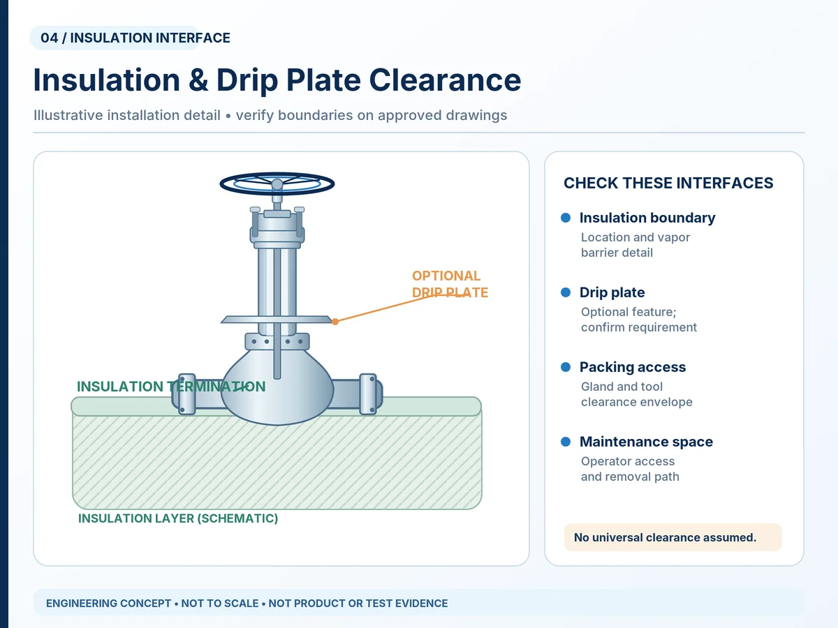
The approved insulation detail should define the termination boundary, thickness, vapor barrier, packing access, tool clearance and any optional drip plate. Some arrangements insulate the body and part of the extension while leaving the packing region accessible. That layout is not universal; the termination position must match the actual design.
Drip Plate Position, Condensation and Moisture Control
A drip plate, where specified, primarily helps divert condensed moisture away from the insulation interface. It is not a standalone packing heater, thermal barrier or guarantee of packing temperature; nor does it replace a correctly detailed vapour barrier, weather protection or drainage. Its material, geometry and exposure may affect the overall heat-transfer arrangement, but any claimed change in packing temperature requires configuration-specific calculation or test evidence. Confirm its position and potential interference with stem movement, mounting hardware and maintenance access. The illustration shows an optional feature, not a universally required detail.
Cold-Box Penetration, Packing Access and Maintenance Clearance
Cold-box installations place additional requirements on the enclosure penetration, exposed bonnet section and operator location. The valve body may sit inside an enclosure while packing and actuation remain accessible outside. The design review should address insulation boundaries, thermal movement, leak-tight enclosure interfaces, operator envelope, gland access and component replacement space.
Illustrative cold-box coordination: If a cold-box roof is raised or the insulation penetration is shifted after valve procurement, the external gland-access envelope and bonnet-exposure assumptions can change. Recheck the penetration detail, packing access and thermal basis against the final as-built interface before approving the installation arrangement.
Installation acceptance check: require a coordinated section showing the enclosure penetration, vapor seal, removable insulation where specified, gland tool access, full operator travel and nearby obstruction envelope. Ask the piping/insulation contractor to confirm that access can be maintained without damaging the vapor barrier or exposing personnel to an unassessed cold surface. No universal clearance dimension is assigned here.
An additional extension can improve access in one arrangement while increasing total height, mechanical loads or installation interference in another. The actual cold-box dimensions and valve drawing should be coordinated before fabrication.
6. How Do Valve Orientation and Actuation Affect Bonnet Design?
Orientation can change the fluid environment and thermal behavior of the extended region. A qualified vertical arrangement cannot automatically be assumed suitable for an inclined or horizontal position.
Stem Orientation in Liquid and Gas Services
Some liquid-service designs rely on a specified vapour-column arrangement or internal geometry to reduce liquid exposure at the packing region. Gas-service heat transfer may differ. The acceptable stem orientation depends on valve type, construction, phase, installation arrangement, manufacturer instructions and the controlled project standard; the evidence for a vertical isolation valve cannot automatically be transferred to an inclined control valve. This article does not prescribe a universal inclination angle.
Scope check: a globe-shaped valve used for modulating control is not automatically within the isolation/check-valve scope of ISO 28921-1:2022 simply because it has an extended bonnet. Establish the valve’s actual duty and applicable product/control-valve requirements separately before specifying extension dimensions or test acceptance.
Manual Operators, Gearboxes and Actuator Clearance
Handwheels, gearboxes and actuators require adequate access and appropriate environmental protection. Verify their position relative to insulation and cold surfaces, available maintenance space and required operating loads. Actuator selection requires confirmed torque or thrust under relevant differential-pressure and temperature cases, operating time, power or air supply and required failure action.
Actuation boundary: A cold-qualified valve body does not by itself qualify its gearbox, electric drive, pneumatic accessories or limit switches for the local ambient and potential frost exposure. Request the manufacturer’s cold operating torque or thrust basis, operator environment and installation envelope; size actuators only from the duty-specific loading data.
Stem Support, Thermal Movement and Operating Loads
Longer extensions can change stem guidance, lateral stiffness, alignment, expansion effects and support loads. A thermally beneficial extension is not necessarily mechanically preferable. The manufacturer should confirm the complete design rather than proposing maximum length without structural evaluation.
7. Cryogenic Valve Extended Bonnet Selection Matrix

The following matrix supports preliminary engineering screening and supplier technical comparison. It is not an acceptance certificate or a replacement for design calculations.
| Service / installation condition | Primary design concern | Engineering evidence to request |
|---|---|---|
| Exposed cryogenic piping | Packing temperature and non-cold-box vapour-column dimension | Correct reference datum, governing temperature/size table, packing limits and thermal assumptions |
| Heavily insulated body | Insulation termination and gland access | Insulation detail and maintenance clearance |
| Cold-box installation | Enclosure penetration and cold-box extension length | Flow-centreline-to-packing datum, applicable controlled table and approved cold-box interface drawing |
| Inclined stem | Orientation-dependent thermal and operating performance | Approved orientation envelope and qualification coverage |
| Actuated valve | Operator environment and mechanical loads | Mounting geometry and validated torque / thrust basis |
| Limited installation height | Reduced extension and access conflicts | Alternative design review, calculation or representative tests |
| Repeated cooldown | Transient temperature and contraction | Material review, transient assumptions and test coverage |
| Unknown minimum temperature | Incomplete thermal design basis | Clarified process datasheet before approval |
Exposed Installation Versus Cold-Box Installation
Exposed/non-cold-box valves require realistic ambient and insulation assumptions and review of the vapour-column reference between the packing-box underside and the appropriate lower guide/extension datum. Cold-box designs additionally require enclosure penetration and maintenance interfaces, with the bonnet-extension reference from the flow-passage centreline to the packing-chamber underside. These are different engineering measurements: obtain a labelled section and the correct controlled-standard table for each design. Neither arrangement can be approved from overall bonnet height alone.
What Changes When Insulation or Orientation Is Restricted?
If the piping arrangement restricts insulation or orientation, a supplier may need a revised extension or an alternative valve configuration. Document deviations, effects on the thermal basis, mechanical interfaces and the evidence used to qualify the proposed change.
8. How Should Extended Bonnet Design Be Verified?
Verification connects the specified duty to applicable standards, controlled drawings, material documentation and tests. A general product description is not a substitute for those records.
Applicable Cryogenic Valve Standards and Scope
ISO 28921-1:2022 specifies design, dimensional, material, fabrication and production-testing requirements for covered metallic low-temperature isolating valves and check valves, with a stated design low-temperature service range from −50°C down to −196°C. Its scope excludes safety and control valves and relevant valves designed under the cryogenic-vessel framework of ISO 21011. Confirm size, class and actual product coverage before applying it.
ISO 28921-2:2015 covers type testing in its stated range; ISO currently identifies the 2015 edition as published and a replacement work item as under development. Its published scope does not generally evaluate actuators unless integral to the valve. BS 6364:1984 was withdrawn by BSI on 23 July 2021; treat any project reference to it as a contract-specific issue to resolve, not as an automatically current requirement.
ANSI/MSS SP-134-2025, Valves for Cryogenic Service, Including Requirements for Body/Bonnet Extensions, is a published Standard Practice for specified metallic cryogenic valves. It covers supplementary requirements for materials, design, dimensions, fabrication, non-destructive examination and pressure testing and is used alongside relevant parent valve-product standards where specified. It does not automatically replace ISO 28921 requirements or apply to every valve duty; the contract must establish the governing standard, edition, precedence and any deviations.
| Standard / status | Relevant scope | Verificación del comprador |
|---|---|---|
| ISO 28921-1:2022 — published | Design, dimensions, materials, fabrication and production testing for covered metallic isolating and check valves | Confirm valve scope, applicable extension dimension, minimum design temperature and purchase-order exceptions; excludes control/safety valves |
| ISO 28921-2:2015 — published | Low-temperature type testing of covered isolation valves | Match tested configuration and acceptance scope; do not treat ordinary actuator qualification as included |
| ANSI/MSS SP-134-2025 — published | Additional cryogenic metallic-valve requirements, including body/bonnet extensions, in conjunction with relevant parent standards | Confirm parent product standard, contract edition, dimensional/test obligations and any stated exceptions |
| BS 6364:1984 — withdrawn | Historical cryogenic valve specification | Resolve legacy contractual references rather than present it as a current standard |
Scope and precedence: ISO 28921-1:2022 explicitly excludes control valves and safety valves; its requirements for covered valves are applied with the relevant product standard according to the adopted specification. MSS SP-134-2025 identifies complementary cryogenic requirements alongside parent product standards. If both are cited, document the purchaser’s governing edition, requirement hierarchy and technical differences instead of claiming that compliance with one automatically satisfies the other.
A standard’s existence does not prove the conformity, certification or test status of an individual Raymon Valve product.
Thermal Calculations, Temperature Mapping and Design Evidence
When needed, analysis should state fluid and ambient temperatures, material properties, geometry, insulation boundaries, relevant contacts and thermal assumptions. Temperature-map reports should identify measurement positions, test configuration, stabilization criteria, actual results and any differences from the ordered arrangement.
An exposed test without the project insulation or cold-box conditions cannot automatically support a materially different installed arrangement.
Cryogenic Type Testing Versus Production Testing
Type testing supports a defined qualification scope. Production testing checks the manufactured item against its required production criteria. Ambient shell or seat pressure testing is not equivalent to evaluation at cryogenic temperatures. Similarly, seat leakage, shell integrity, external leakage, functional operation and packing temperature are distinct verification questions.
Qualification coverage: ISO 28921-2:2015 does not evaluate a separate valve actuator unless it is integral to the valve, as stated in its published scope. A cryogenic valve type-test record should therefore not be presented as standalone evidence of an actuator package’s low-temperature rating. Review the tested valve build, operating method and any separate actuator qualification documentation.
For a broader explanation of testing evidence, consult Raymon Valve’s Cryogenic Valve Testing & Qualification page. The governing acceptance criteria must still come from the project specification and applicable standard.
| Verification scope | Primary question | Evidencia a solicitar | What it does not establish |
|---|---|---|---|
| Design / dimensions | Does the proposal meet the applicable design basis and drawing requirements? | Applicable edition, approved sections, bill of materials and dimension references | Actual packing temperature in every installation |
| Type qualification | Has a defined valve design been tested under specified low-temperature conditions? | Test report, tested model, construction, conditions, limits and acceptance | Automatic coverage of changed geometry or insulation |
| Order production inspection | Has the supplied item met the required manufacturing and production-test plan? | Tag/serial-linked ITP, procedures, results and deviations | Unperformed type tests or unrelated special qualifications |
| Packing thermal review | Is packing exposure acceptable in the specified installation? | Temperature locations, analysis/test results and packing limits | General shell or seat tightness by itself |
| Actuator / assembly | Can the complete operated package function under the specified conditions? | Cold load basis, ambient rating and assembly verification where required | Suitability inferred solely from the valve’s type-test certificate |
Drawing, Inspection and Documentation Requirements
Technical submissions may include general arrangement and section drawings, extension dimension references, packing and gasket specifications, material traceability, approved test procedures, relevant qualification evidence, production inspection records, permitted orientation and a technical deviation schedule.
Evidence traceability: ask the supplier to tie the nominated design, materials, heat treatment where applicable, packing system, test procedure and acceptance criteria to the quotation and supplied valve tags. Material test certificates, impact-test evidence where required, NDT/PMI reports and inspection witness records should be requested only where relevant to the agreed ITP and project specification. No general certificate can replace item-specific evidence.
Refer to the Valve Standards Resource for wider standards context, while confirming official editions and applicability for this project.
9. Common Extended Bonnet Design and Specification Mistakes
| Specification mistake | Potential consequence | Recommended verification |
|---|---|---|
| Comparing overall height instead of defined extension length | Wrong geometry accepted | Confirm standard and drawing reference points |
| Assuming packing must always stay above 0°C | Incorrect requirement or selection | Review the complete packing qualification |
| Ignoring insulation termination | Unexpected packing temperature or inaccessible gland | Review approved insulation and thermal details |
| Overlooking moisture-management features | Condensation may affect insulation integrity | Confirm vapor barrier and optional drip plate details |
| Omitting installation orientation | Thermal or operating conditions differ from design | Obtain permitted-orientation confirmation |
| Ignoring cold-box access | Maintenance or operation obstructed | Check penetration and service envelope |
| Accepting a generic test certificate | Qualification coverage uncertain | Match tests to exact configuration and criteria |
| Ignoring actuation loads | Inadequate operating margin | Review verified torque/thrust and package design |
Selecting Bonnet Length Without a Defined Thermal Basis
A nominal length without reference dimensions and thermal assumptions is not an adequate technical submission. Verify the applicable dimension and what the supplier’s evidence actually supports.
Insulation Interference and Inaccessible Packing
A design that thermally separates the packing but prevents inspection or maintenance can remain unsuitable for the project. Ensure gland access is reviewed jointly with the insulation scheme.
Treating a Cryogenic Test Certificate as Universal Approval
A test report applies to the article, configuration, procedure and acceptance scope stated in that report. Changes to packing, materials, geometry, insulation or orientation may require further engineering justification.
10. Cryogenic Valve Extended Bonnet RFQ Checklist

A complete RFQ helps procurement teams obtain technically comparable proposals and identify assumptions before purchase order placement.
Pre-PO approval gate: Record each bidder’s extension dimension and datum, packing qualification, insulation termination, approved orientation, cryogenic test coverage, document submissions, witness points and exclusions in the same comparison sheet. Mark unresolved data as Clarification required rather than treating a missing value as an assumed compliance statement.
Process and Thermal Design Inputs
| RFQ field | Buyer input | Supplier response / evidence |
|---|---|---|
| Valve function and type | Isolation, non-return, control or other duty | Proposed product construction and applicable scope |
| Medium / phase | Composition, liquid or vapor, operating cases | Compatibility and thermal review |
| Design temperatures | Minimum, maximum and relevant transients | Thermal and materials design basis |
| Design pressures | Normal and maximum credible cases | Pressure-temperature rating review |
| Size / class / ends | NPS/DN, Class/PN and connection details | Dimensional conformance |
| Bonnet extension | Geometry requirement or packing temperature objective | Defined drawing dimensions and rationale |
| Empaquetadura | Leakage and operating requirements | Packing-system details and qualification |
| Orientación | Installed stem direction | Permitted installation arrangement |
| Aislamiento | Thickness, type and termination | Approved interface section |
| Cold-box | Penetration and enclosure geometry | Coordinated GA and maintenance envelope |
| Operator / actuator | Access, speed, fail position and supply | Environment and verified loads |
Required Drawings, Inspection and Test Documents
| Document | Por qué es importante |
|---|---|
| Dibujo de disposición general | Checks external dimensions and installation envelope |
| Dibujo seccional | Identifies bonnet, stem, packing and internal geometry |
| Thermal design evidence | Establishes assumptions and expected packing exposure |
| Material documentation | Supports composition and traceability review |
| Cryogenic test procedure | Defines actual conditions and acceptance criteria |
| Qualification report | Establishes tested configuration and coverage |
| Production test records | Documents order-specific verification |
| Plan de Inspección y Pruebas (ITP) | Defines inspection points and witnessing scope |
| Technical deviation list | Identifies departures from the purchase specification |
For a relevant product example, review Raymon Valve’s Válvula de globo criogénica page. Product-specific low-temperature suitability must still be confirmed against the exact selected configuration and purchase datasheet.
Technical Bid Normalization Before Purchase Order
Send the same RFQ basis to each supplier and require an explicit compliance, exception or evidence-pending response for each technical line. A lower quoted price does not establish comparability where the bonnet measurement, insulation interface or test scope differs. The following is a procurement review template, not a statement about any actual supplier.
| Bid comparison item | Common comparison basis | Supplier declaration required | Disposition if different or missing |
|---|---|---|---|
| Extension / reference | Same dimension datum and governing standard edition | Dimensioned drawing and standard basis | Clarify / record a technical deviation |
| Thermal / packing design | Same process cases, ambient limits, insulation and packing objective | Qualified packing range and relevant analysis/test rationale | Hold thermal acceptance pending applicable evidence |
| Instalación | Same orientation, cold-box geometry, operator envelope and access | Approved interface drawing and permitted orientation | Resolve layout before dimension approval |
| Materials / leakage | Same pressure-temperature and external/seat leakage specification | Material and seal schedule; acceptance criteria | Document the departure, obtain engineering disposition |
| Tests / deliverables | Same qualification scope, ITP, witness points and handover records | Included tests, excluded tests, records and commercial consequences | Normalize scope and cost before commercial award |
Illustrative decision path: if the bid meets the nominal valve class but omits the specified insulation termination and packing temperature evidence, mark those items Evidence pending rather than Compliant. Resolve the discrepancy with the supplier and responsible engineer before approving the purchase. The example does not represent a real Raymon Valve project.
11. Frequently Asked Questions
¿Por qué las válvulas criogénicas utilizan bonetes extendidos?
Extended bonnets increase separation between the cold process body and the stem-packing region. In a suitable design, this helps manage the packing temperature and accommodates access above insulation. The actual benefit depends on the extension geometry, ambient exchange, insulation, orientation and qualified sealing system; an extension alone does not establish cryogenic suitability.
How is the required extended bonnet length determined?
The length is assessed against the governing standard’s applicable dimensions, actual valve geometry, minimum process temperature, packing limits and installation details. Engineers must identify the correct dimension reference before comparing quotations. Nonstandard thermal or installation conditions may require further calculations, qualification coverage or testing.
Does an extended bonnet keep valve packing above freezing temperature?
Not necessarily. Some packing systems may be qualified for temperatures below 0°C. The design objective is to keep the complete sealing system within its confirmed operating envelope. Whether that is achieved depends on the actual thermal paths, insulation boundary and relevant duty, not simply on bonnet length.
Where should insulation terminate on a cryogenic valve?
The approved insulation and thermal design should identify the termination. Depending on the valve configuration, insulation may surround the body and part of the extension while maintaining access to the gland and operator. Moisture barriers, optional drip plates, cold-box geometry and maintenance clearance also influence the detail.
How does cold-box installation affect extended bonnet selection?
A cold box adds requirements for enclosure penetration, insulation interfaces and external maintenance access. The bonnet may pass through the enclosure, but dimensions and permitted orientation must suit the actual installation. A controlled arrangement drawing and relevant thermal and qualification evidence should be reviewed before approval.
Does cryogenic testing confirm extended bonnet thermal performance?
Cryogenic testing can provide supporting evidence only for the configuration and conditions it actually covers. A leakage test does not necessarily demonstrate packing temperature under another insulation arrangement. Check temperature measurements where required, the tested orientation and geometry, plus the distinction between qualification testing and production testing.
12. Request a Cryogenic Valve Bonnet Design Review
Extended-bonnet selection requires coordination between process, valve, piping, insulation and procurement engineering. Confirm the service data, permitted orientation, packing envelope, extension geometry, insulation interfaces and qualification requirements before approving a proposal.
Request Cryogenic Valve Bonnet Design Review. Submit the valve tag and function, fluid/phase, minimum/normal/maximum and cooldown temperatures, design pressure, size/class/ends, installed stem orientation, insulation thickness and termination, cold-box penetration or clearance sketch, packing and external-leakage criteria, operator/actuation requirements, and the governing project standards with editions. Attach the datasheet and existing GA/insulation drawings. State whether you need a proposal, a drawing review, a technical deviation comparison or a defined cryogenic testing and inspection scope.
Provide the project datasheet, actual insulation or cold-box layout, permitted orientation and requested evidence/test scope. The proposed design, deviations and available documentation require project-specific confirmation.
Engineering note: This article supports preliminary design review, specification development and technical bid evaluation. It does not establish performance or conformity of a particular valve. Final selection must follow confirmed process data, applicable standards, approved manufacturer drawings, material and packing qualification, and project-specific verification.
Content and evidence status: Prepared by the Raymon Valve Technical Content Team for engineering screening and RFQ preparation. All six illustrations are explanatory concepts, not approved product drawings, ISO diagrams or test results. No Raymon Valve model-specific thermal calculation, validated temperature map, actual customer test record, named individual technical reviewer or certification evidence was supplied for this article. Future product-specific drawings and test evidence may be incorporated after verification; acceptance of any offered valve still requires controlled supplier documentation and project engineering approval.
 Spanish
 English
 German
 Arabic
 French
 Italian
 Portuguese
 Russian