
Control Valve Troubleshooting & Corrective Sizing Review
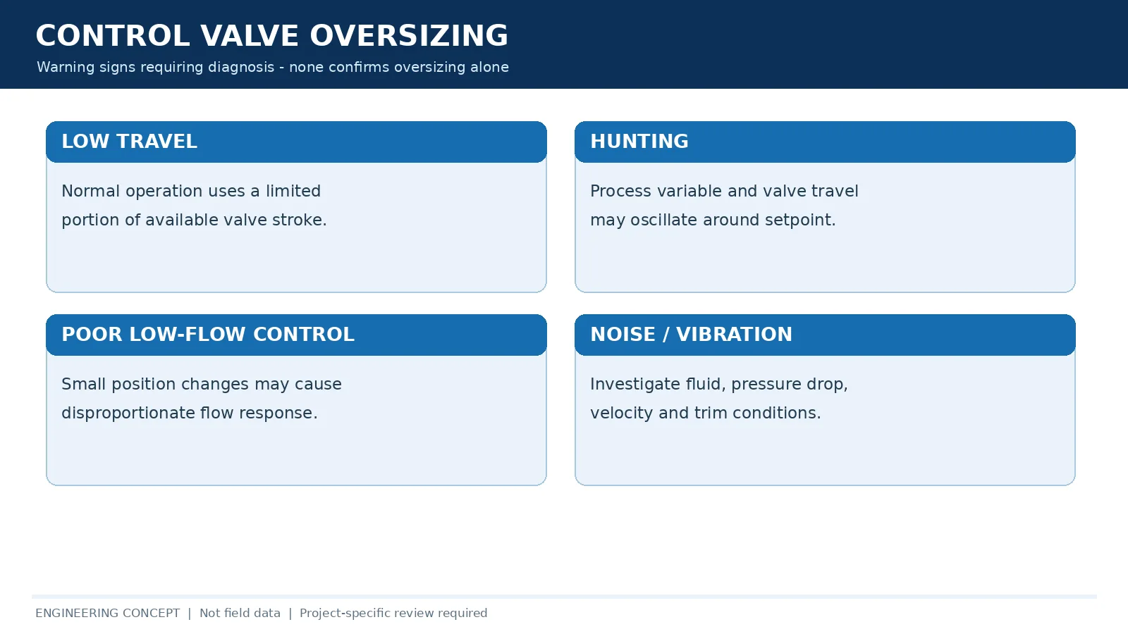
Control valve oversizing means the installed valve or trim has more flow capacity than the process needs across its actual operating range. Normal flow may then be controlled over a narrow valve travel interval, potentially increasing installed gain, hunting and low-flow sensitivity. However, low travel, noise or oscillation alone does not prove oversizing: friction, positioner deadband, tuning and changed system pressure can create similar symptoms. A defensible corrective review compares matching minimum, normal and maximum duty cases, valve-specific Cv/travel data, measured movement and process response before recommending trim replacement, resizing or control-loop changes.
For available equipment categories and project-defined modulating service, see Raymon Valve’s control valve types and technical options page. This article concerns field diagnosis and does not replace the product selection or sizing process.
1. What Is Control Valve Oversizing?
A control valve is oversized when its capacity is unnecessarily high relative to the actual flow range it is expected to regulate. The main concern is not simply whether it passes maximum flow: some design margin may be necessary for unusual cases, future requirements or uncertainties. Oversizing becomes an operating problem when the excess capacity reduces control resolution or produces an unsuitable installed response over the required range.
Oversized Cv vs. oversized valve body
Valve body diameter and flow capacity are related but not interchangeable. A larger body may contain reduced-capacity trim, while a line-sized valve may still have excessive trim capacity for the duty. Evaluate the body and end connections, rated Cv, actual trim construction, inherent flow characteristic, required Cv at each operating case and the pressure drop available to the valve.
Maximum-flow capability is not proof of controllability
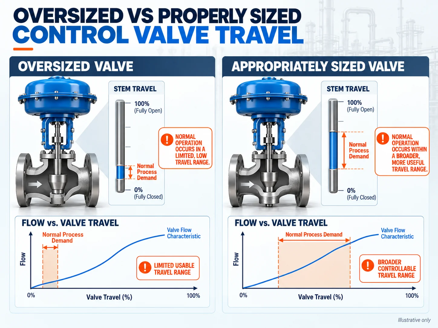
A valve can meet its maximum design-flow requirement yet perform poorly near normal production. If regular demand is substantially below the original basis, normal flow may occur across only a small part of available stroke. The installed flow-versus-travel response—not nominal size alone—determines whether useful regulation is available.
2. Common Symptoms of an Oversized Control Valve
Persistent low valve travel
A valve operating near the seated end throughout normal production can have limited travel available for fine adjustments. This may make friction, deadband and positioner resolution more consequential. There is no single travel percentage that proves oversizing for every design; compare measured travel with the valve’s documented trim curve and confirmed process cases.
Illustrative field scenario: A valve selected for a planned expansion operates at low travel after production remains below the design rate. The sensible first step is to compare present minimum/normal/maximum flow and matching pressure conditions with the original sizing sheet and selected trim curve—not to assume that a small position indication proves the valve is defective.
Poor usable rangeability
Inherent rangeability describes a valve’s defined capacity range under specified characterization conditions. Installed controllability reflects usable control performance in the actual piping system. Excess capacity does not automatically change catalog inherent rangeability, but it may concentrate necessary process flows into a narrow interval of travel and reduce practical turndown or control resolution.
Hunting and process oscillation
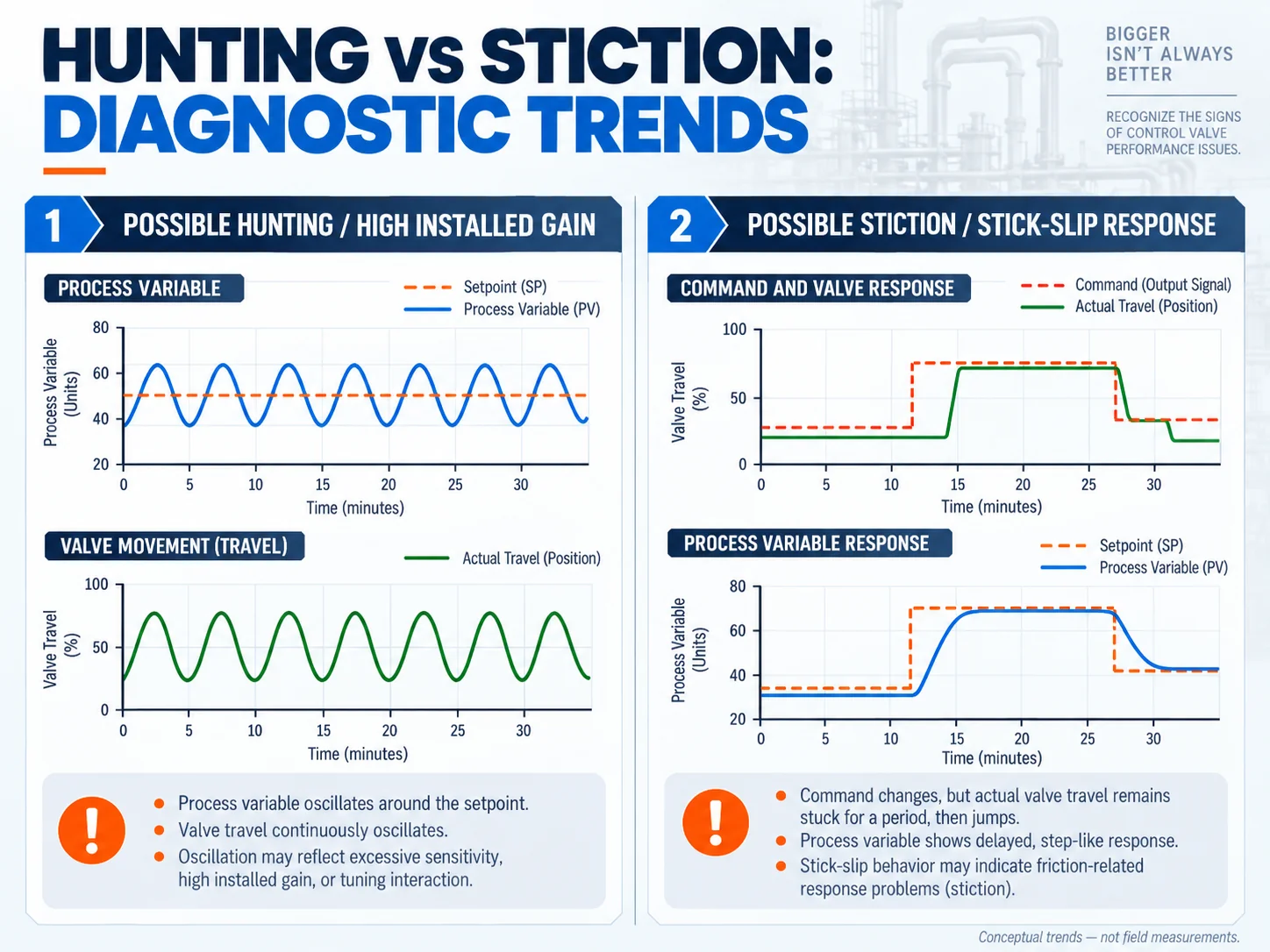
When local installed gain is high, small movement can cause relatively large flow changes, potentially contributing to controller overcorrection and cycling. However, incorrect PID settings, process disturbances, valve friction, deadband and interacting loops can also cause oscillation. Diagnose these factors before deciding that the valve itself is too large.
Noise and vibration
Throttling can generate turbulence, localized velocity and pressure-recovery effects. Depending on service, aerodynamic noise, liquid cavitation or flashing may be involved. Noise is not proof of oversizing and requires its own assessment of fluid properties, valve pressure drop, recovery behavior and downstream piping.
Unstable low-flow operation
Erratic response at minimum demand may reflect installed gain, unsuitable characteristic, narrow usable stroke, packing friction, inadequate actuator response or system-pressure fluctuations. Review mechanical behavior and flow response together.
3. Why Oversizing Can Cause Poor Control Performance
Excess capacity can compress useful travel
If rated capacity is much greater than the duty requires, normal demand may be met at limited opening. A compressed operating interval leaves less stroke available for small corrections. Whether this produces unacceptable controllability depends on the actual installed characteristic, friction and required process accuracy.
Installed gain and flow sensitivity
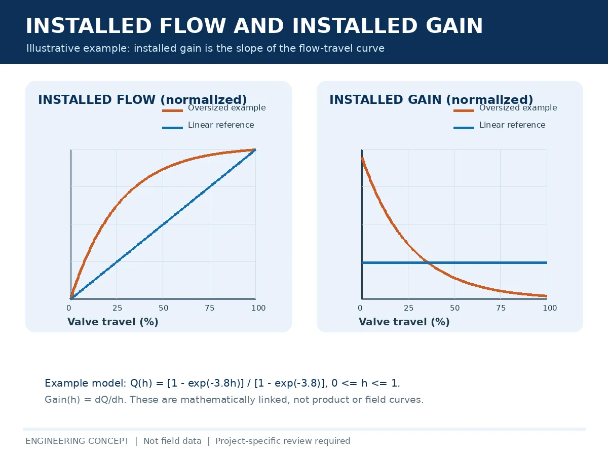
Calculation boundary: Installed gain should be evaluated from a consistent, stated normalization of process flow and actual valve travel. A conceptual graph is not evidence of the installed gain for a specific tag. Use vendor Cv-versus-travel data and a process-system model; keep the assumptions, units and operating points with the review record.
For a consistently defined operating case, normalized installed gain can be expressed conceptually as:
Here, Q is flow, Qref is a stated reference flow and h is normalized valve travel. This is an illustrative definition: normalization and calculation basis must be stated consistently. Excessive local gain can magnify small positioning deviations, whereas very low gain may produce weak flow response. The target is suitable gain across the operating range, not maximum or minimum gain in isolation.
The installed-gain discussion should be interpreted alongside recognized technical treatment of installed performance, such as the Valmet installed-performance overview. A schematic graph must not be treated as a valve-specific derivative or a calculated sizing result.
Inherent characteristic vs. installed characteristic
Inherent characteristic describes Cv-versus-travel behavior under defined conditions; installed characteristic describes resulting flow response after the entire piping system’s resistance and valve pressure-drop distribution are considered. Equal-percentage or linear trim should not be recommended without comparing candidate installed flow curves for the actual process. See Raymon Valve’s installed flow characteristic selection guide.
4. Is It Really Oversizing? Other Causes to Eliminate First
Stiction and packing friction
Static friction can delay stem movement while controller output continues changing. Once movement begins, the valve may jump, creating a stick-slip response that resembles poor regulation. Compare command and actual-travel data, actuator pressure and maintenance records before attributing the symptom to capacity.
Actuator or positioner deadband
Backlash, linkage clearance and feedback problems can produce an input-change range without the expected movement. Trend data and direction-dependent response checks help distinguish deadband from sizing issues. A valve can also have both an oversized trim and a mechanical fault.
Illustrative diagnostic scenario: Controller output changes while measured travel remains nearly stationary, followed by an abrupt response. Review travel feedback, linkage, positioner settings, packing load and friction before buying a smaller valve. The same symptom can be made more disruptive by excessive installed gain, so both mechanisms may require attention.
Controller tuning and system changes
Excess proportional response, inappropriate integral settings, process lag and interacting loops can cause cycling. Changes in pump head, production rate, upstream pressure, equipment or line resistance may also shift the actual valve pressure drop away from its original sizing basis. Compare previous and current system conditions rather than treating the original design case as permanent.
Cavitation, flashing and other noise mechanisms
For liquids, examine vapor pressure, pressure recovery and whether vapor formation collapses or persists downstream. For compressible service, assess pressure ratio, velocity and aerodynamic-noise conditions. These checks remain necessary even if oversizing is also suspected.
Illustrative noise scenario: A liquid-service valve is loud at a particular pressure-drop case. Noise is not sufficient evidence of oversizing; verify inlet and outlet pressures, vapor pressure, fluid properties, valve recovery behavior and downstream geometry before choosing reduced-Cv trim. A correction in capacity alone may leave cavitation or outlet-velocity limits unresolved.
5. How to Verify Control Valve Oversizing
Field safety boundary: Do not force valve strokes, bypass interlocks, alter controller tuning or disturb pressure-containing components on an operating process without a site-approved procedure, risk review and responsible authorization. Any intervention requiring maintenance must follow the applicable isolation, depressurization, lockout/tagout and work-permit controls.
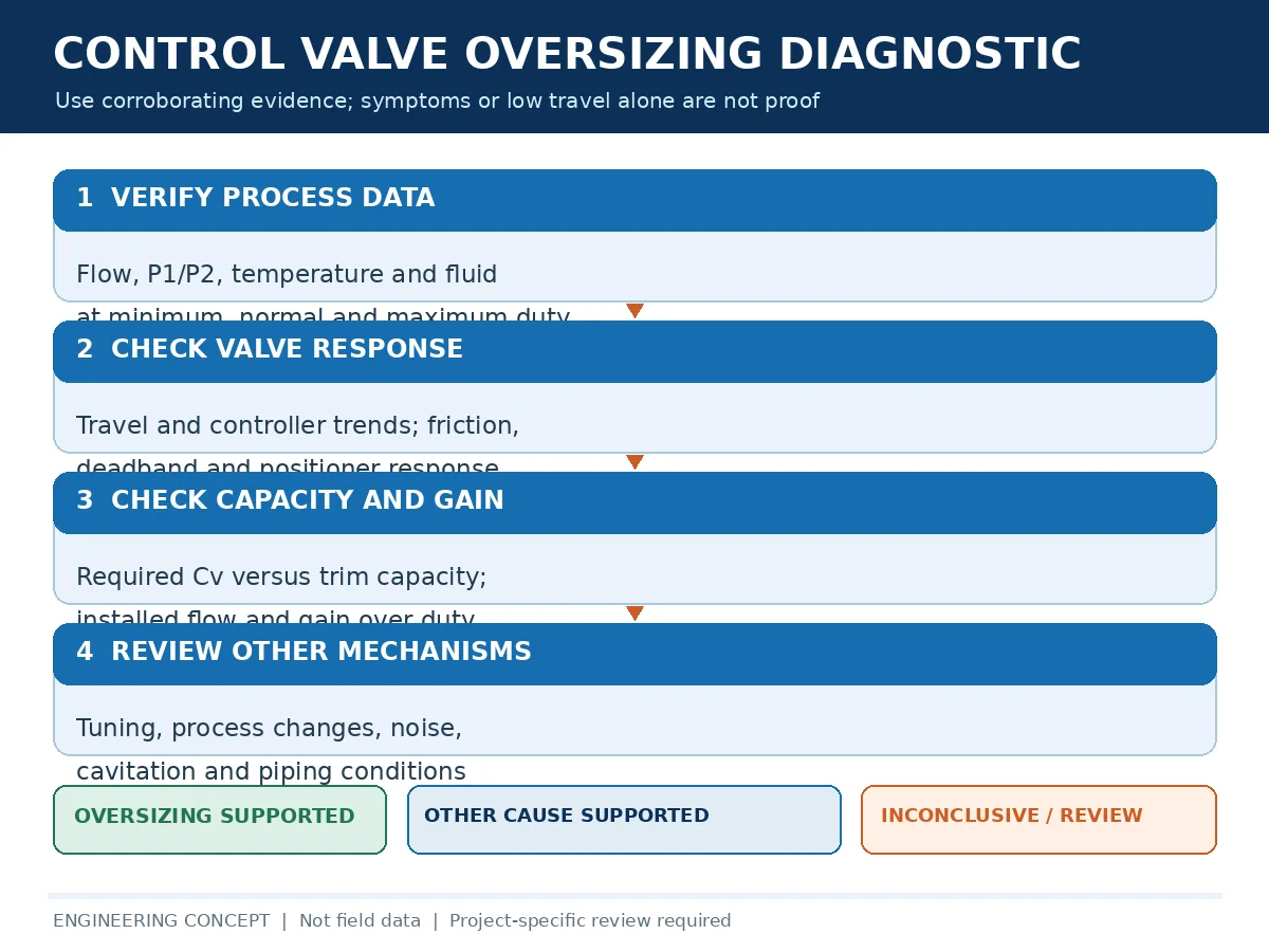
Step 1 — Collect matching operating cases
Record minimum, normal and maximum flow, fluid composition and phase, temperature and the inlet/outlet pressures corresponding to each flow case. Include relevant startup and abnormal cases and specify the required control objective. Mixing pressure values from one case with flow from another can distort sizing results.
Step 2 — Review original sizing and installed trim
Obtain the valve datasheet, original calculation, model, installed trim, rated Cv, inherent characteristic and documented Cv-versus-travel data. Check whether the original design included future capacity margins and whether equipment or process conditions have changed. The control valve sizing guide provides the broader input and calculation framework.
Step 3 — Calculate required Cv for each case
Use project-applicable sizing equations and the appropriate liquid or compressible-flow parameters, including corrections and service limitations where needed. Compare calculated required capacity against available trim capacity at the actual operating differential pressure. Rated Cv alone does not describe the full controllability of the installed valve.
Step 4 — Compare controller, travel and process trends
Review setpoint, process variable, controller output, commanded valve position, actual travel and available actuator pressure. Look for delayed motion, oscillation, travel clustering, saturation and load-dependent symptoms. Operational testing must follow approved site procedures.
Step 5 — Model installed gain
Determine installed flow versus travel throughout the required range using valve-specific data and the system resistance model. Evaluate local gain at minimum, normal and maximum operating conditions, the remaining capacity margin and positioning sensitivity.
Step 6 — Perform hydraulic and acoustic checks where relevant
Review cavitation, flashing, compressible-flow limitations, downstream velocity and noise against project constraints. The maximum-risk operating point may differ from the maximum-flow case.
Step 7 — Document the conclusion and uncertainties
Record the evidence for capacity mismatch, alternative causes ruled in or out, outstanding measurements, candidate corrective options and required engineering approvals. If the relevant sizing inputs or trim data are missing, retain an inconclusive finding rather than declaring the valve oversized.
Evidence confidence: supported, alternative cause or inconclusive
Separate the observed symptom from the diagnosis in the review report. Mark oversizing supported only when verified operating cases, manufacturer trim data and installed-performance calculations indicate excess capacity or unsuitable usable travel. Mark other cause supported when command/travel evidence, instrument checks or process analysis explains the issue without a capacity mismatch. Use inconclusive when P1/P2, fluid properties, trim identification, trend synchronization or other critical evidence is missing. Multiple findings may coexist, and a corrective decision can remain conditional.
6. Control Valve Oversizing Diagnostic Matrix
| Observed symptom | Possible mechanisms | Свидетельства для проверки | Corrective review direction |
|---|---|---|---|
| Persistent low travel | Excess trim capacity or reduced demand | Operating cases, documented Cv curve, travel feedback | Revisit sizing and trim capacity |
| Hunting near normal load | High installed gain, PID interaction, friction | Controller and positioner trends, installed gain, tuning history | Separate mechanical and loop causes from sizing |
| Poor minimum-flow control | Limited useful stroke, stiction or feedback resolution | Minimum-flow calculation and command/travel response | Review trim and actuation behavior |
| Large flow changes after small movement | Excess local installed gain | Flow-versus-travel model and verified trends | Compare capacity and trim characteristic options |
| Command changes without movement | Deadband, stiction or linkage faults | Command/position trends and inspection | Mechanical or positioner investigation |
| Noise at small opening | Turbulence, cavitation, flashing or aerodynamic effects | Fluid, pressure, recovery and acoustic calculations | Independent hydraulic/acoustic review |
| Problems after process modification | Changed system pressure-drop allocation | Original and current operating cases | Recalculate installed performance |
7. Corrective Options for an Oversized Control Valve
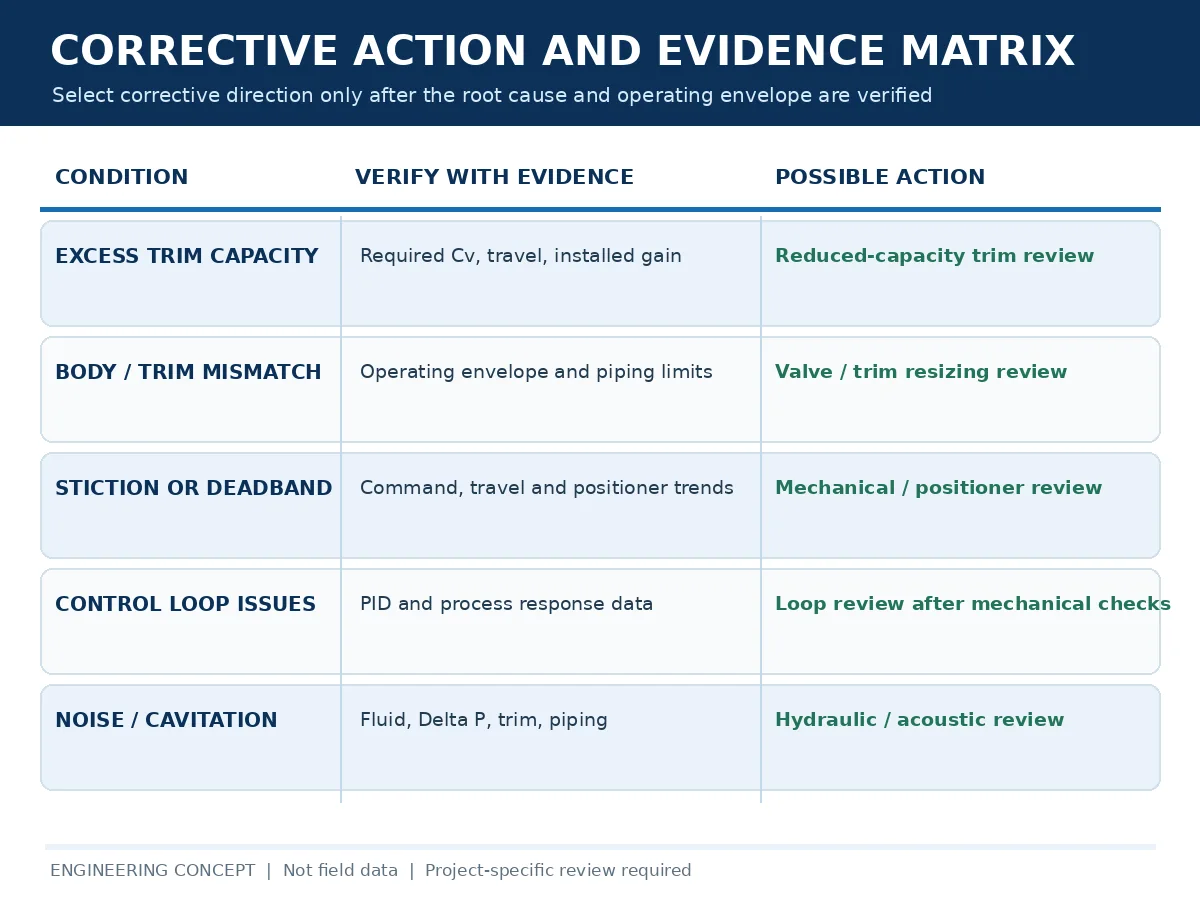
Reduced-capacity trim
When the valve body remains mechanically suitable but trim capacity is excessive, a compatible reduced-capacity trim may improve the useful travel range. Confirm maximum flow, minimum controllable demand, shutoff and leakage, materials, flow regime, cavitation/noise constraints and actuator suitability. Compatible trim is model-specific and not universally available.
Resizing or replacing the valve
A replacement may be needed when the existing body/trim combination cannot meet the specified installed performance. A smaller valve can affect reducers, installation space, pressure losses and piping loads; review these consequences along with full operating duty and shutoff requirements before approval.
Illustrative RFQ scenario: A proposal offers a smaller nominal valve body, but its trim characteristic, installed travel prediction and maximum-duty capacity are not provided. Request the sizing calculation at matching operating points, predicted travel, shutoff and actuator data, required piping changes and an explicit deviation list before technical acceptance. Nominal size alone does not establish improved control performance.
Changing the flow characteristic
A different inherent characteristic can improve the installed flow response under some system conditions, but it does not automatically correct excess rated capacity. Compare candidate installed curves using consistent process assumptions.
Actuator and positioner review
Verify thrust or torque across the revised travel range, supply pressure or power, fail action, response requirements, positioner compatibility, stroke limits and required seat force. A no-load stroke test is not evidence of full-duty actuator suitability.
Retuning the controller
Tuning may need reassessment after trim or valve changes, but retuning alone must not hide unresolved mechanical or sizing faults. Changes to operating control loops require the site’s authorized change-management and safety procedures.
When valve replacement is not the first step
Calibration issues, packing friction, poor tuning, linkage faults and process changes may be the dominant causes. Root-cause evidence should lead the corrective action, not the visual impression of an oversized valve.
Corrective-option evidence required for technical comparison
| Candidate action | Evidence required before approval | Main limitation or exclusion |
|---|---|---|
| Reduced-capacity trim | Manufacturer compatibility, calculated travel over all flow cases, max-flow margin, leakage, noise and actuator checks | Not valid if the existing body, pressure boundary or geometry cannot meet service requirements |
| Valve replacement | Revised sizing sheets, installed characteristic, piping/reducer review, materials, shutoff, actuator and test scope | A lower Cv alone does not prove acceptable minimum-flow control |
| Positioner or mechanical repair | Instrument diagnostics, command-versus-position traces, inspection and verified corrective test | Will not solve excessive trim capacity if that is also present |
| Control-loop retuning | Approved dynamic review, documented settings, before/after loop response and protection review | Must not compensate for a hazardous or unsuitable mechanical configuration |
| Hydraulic/acoustic modification | Operating-case calculations, applicable noise limits, cavitation/flashing and downstream velocity review | Changing trim solely for noise may change capacity and controllability |
8. Engineering Review Checklist Before Changing Valve Size or Trim
| Review category | Требуемая информация | Engineering purpose |
|---|---|---|
| Fluid | Composition, phase, density, viscosity and other relevant properties | Support sizing and service limits |
| Operating flows | Minimum, normal, maximum and special cases | Define required control range |
| Pressures | Valve P1/P2 for each matching operating case | Establish available pressure drop |
| Температура | Operating and design values | Review fluid properties, sizing and materials |
| Installed valve | Body/model/size/rating/end connections | Identify pressure boundary and interfaces |
| Уплотнительная арматура (Трим) | Rated Cv, trim style, characteristic, materials and curve | Compare capacity and controllability |
| Обратная связь по положению | Travel versus load, command versus actual position | Identify operating distribution and friction |
| Control loop | Setpoint, process variable, controller output and trend history | Investigate hunting and tuning interaction |
| Привод | Type, model, supply conditions, required thrust/torque and fail position | Confirm assembly compatibility |
| Hydraulics/noise | Pressure recovery, relevant fluid data, piping and project limits | Assess cavitation, flashing and noise risk |
| Документы | Original sizing sheet, drawings, inspection records and project specification | Support traceability and approval |
What the supplier should confirm
- Sizing results at every specified operating case.
- Proposed trim Cv and characteristic, including travel expectations.
- Installed-gain review and remaining maximum capacity, where applicable.
- Relevant cavitation, flashing and noise assessments.
- Actuator/positioner matching and shutoff performance.
- Materials, testing, inspection, documentation and technical deviations.
- Installation changes and assumptions needing project approval.
Suppliers should quote against identical operating data. Neither a lower rated Cv nor a lower quotation price alone demonstrates better installed controllability.
Acceptance evidence after an approved correction
Before ordering, establish project-specific acceptance criteria for the minimum, normal and maximum operating cases. Depending on service, these may include predicted and verified travel, flow regulation and stability at representative loads, noise limits, shutoff performance, actuator action and full-stroke functionality. After implementation, compare commissioning trends with the accepted baseline under authorized site procedures. A successful shop stroke test alone does not demonstrate installed control performance.
For technical bid comparisons, require each supplier to identify assumptions, excluded operating cases, available test evidence, deviations, installation changes and documentation deliverables. This prevents proposals from being compared on nominal Cv or price alone.
9. Frequently Asked Questions
How can I tell if a control valve is oversized?
Compare the installed valve’s capacity and predicted travel against verified minimum, normal and maximum operating requirements. Low travel is a screening clue; confirmation requires sizing calculations, trim curves, installed-performance review and investigation of alternative causes.
Does low valve travel always mean oversizing?
No. Legitimate low-flow operation, trim characteristic, system pressure conditions and process changes can also produce low travel. There is no universal percentage that independently proves oversizing.
Can an oversized control valve cause hunting?
Yes. Excessive local installed gain can make small travel movements produce large flow changes and contribute to unstable control, but tuning, friction, deadband and process disturbances are alternative causes.
Does oversizing reduce control valve rangeability?
It does not necessarily change specified inherent rangeability. Excess capacity can compress actual process regulation into a narrow travel interval and reduce usable installed controllability.
Can reduced-capacity trim solve control valve oversizing?
Sometimes, if compatible trim exists and calculations confirm that maximum flow, low-flow control, shutoff, materials and actuator performance all remain acceptable.
Should an oversized control valve be replaced or retuned?
The verified root cause determines the action. Retuning may address control-loop issues, while reduced-capacity trim or valve replacement may be needed when the installed valve cannot meet the required operating envelope.
10. Review Low Travel and Unstable Control Before Replacing Your Valve
Request a project-specific corrective review with your existing control valve datasheet, minimum/normal/maximum flow cases and matching pressures, fluid properties, installed trim Cv and characteristic, and controller/positioner trends. Include reported noise or vibration, actuator details and applicable project requirements.
Raymon Valve can receive the technical inquiry and discuss a potential review or quotation scope; availability of model-specific calculations or corrective trim must be confirmed. Final corrective decisions remain subject to confirmed calculations, supplier data and project engineering approval.
Request Control Valve Sizing Review →Technical References
- IEC 60534-2-1 — Industrial-process control valves: Flow capacity, sizing equations. Confirm the applicable edition and corrections against the project specification.
- Valmet — Control Valve Installed Performance. Background on installed characteristics, gain and control response.
- ISA — Using Control Valve Installed Gain Calculations. Technical discussion of installed gain in valve selection.
 Russian
  English
  German
  Arabic
  French
  Spanish
  Italian
  Portuguese