
For a top entry vs side entry ball valve decision, top-entry construction is worth evaluating when keeping the main body in the pipeline can materially reduce piping disturbance and sufficient vertical maintenance clearance is available. Side-entry construction remains practical where split-body access, removable spools or lateral clearance fit the plant maintenance strategy. Neither arrangement alone determines pressure rating, sealing performance or reliability. The final comparison should include body joints, internal access, lifting space, piping work, lifecycle maintenance and supplier evidence.
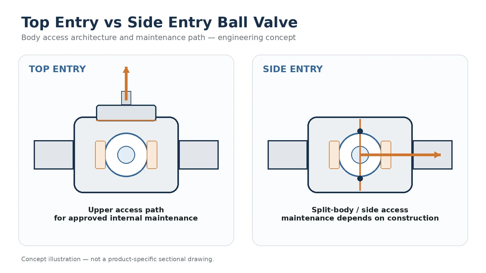
Top Entry vs Side Entry Ball Valve Comparison
| Пункт рассмотрения | Top Entry | Side Entry | Buyer Verification |
|---|---|---|---|
| Internal access | Internals are generally accessed through an upper opening or cover. | Internals are generally assembled through split or multi-piece body sections. | Утвержденный разрезанный чертеж |
| Main body-joint arrangement | Upper cover-to-body connection is an important pressure-boundary interface. | One or more body-to-body joints may form part of the pressure boundary. | Joint geometry, sealing and bolting |
| Body remaining in pipeline | Can be possible during defined internal maintenance, subject to the exact design. | Depends on the specific split-body or multi-piece construction and piping arrangement. | Maintenance procedure |
| Main maintenance space | Vertical access and lifting clearance may be critical. | Axial or lateral dismantling space may be critical. | Plant maintenance envelope |
| Ball and seat access | Typically through the upper opening where the design permits internal extraction. | Typically through separated body sections or another design-specific route. | Extraction sequence |
| Pressure capability | Not determined by entry arrangement alone. | Not determined by entry arrangement alone. | Material, temperature, rating basis and exact design |
| Joint integrity | Cannot be concluded from the number of body joints alone. | Joint design, materials, assembly, inspection and testing | |
The practical question is not simply whether a valve is “top entry” or “side entry.” The buyer should ask how the valve will be opened, which pressure-boundary interfaces will be disturbed, how the ball and seats are removed, what lifting space is required and how much piping disturbance is acceptable during future maintenance.
For the wider product context, review Raymon Valve’s промышленные шаровые краны.
Which Project Data Can Change the Top Entry vs Side Entry Decision?
The preferred body-entry arrangement can change once the actual plant layout and maintenance philosophy are known. Valve size and pressure class alone are not enough. Before comparing supplier quotations, the engineering team should normalize the project inputs that affect access, isolation, disassembly and return to service.
| Входные данные проекта | Why It Changes the Decision | Что подтвердить |
|---|---|---|
| Тип присоединения | A butt-weld valve can create a very different removal problem from a flanged valve installed between removable spools. | Connection type and actual piping layout |
| Available overhead clearance | Top-entry internal extraction can require vertical space above the valve. | Actuator height, cover removal and lifting envelope |
| Available axial or lateral clearance | Side-entry maintenance can require space to separate flanges, spools or body sections. | Pipe movement, flange separation and removal route |
| Valve and component weight | Large bodies, balls, actuators and covers change lifting and maintenance planning. | Valve weight, major component weights and lifting method |
| Shutdown philosophy | A project planning internal overhaul can require different access from a project planning complete valve replacement. | Expected maintenance method and shutdown scope |
| Inspection frequency | Periodic seat or cavity inspection increases the importance of a repeatable internal-access procedure. | Inspection scope and planned maintenance route |
| Расположение седла | Seat retention and extraction paths can determine whether the intended maintenance route is practical. | Sectional drawing and seat-removal procedure |
| Actuation package | Actuators, gearboxes and accessories may need to be removed before internal access. | Actuator removal, lifting and reinstallation procedure |
Because maintenance access is closely tied to how the valve connects to the piping, also review Raymon Valve’s guide to ball valve end connection and piping interface when comparing flanged, butt-weld and other connection arrangements.
What Actually Changes Between Top Entry and Side Entry Ball Valves?
What Is a Top Entry Ball Valve?
A top-entry ball valve is arranged so that major internal components can be accessed through an opening in the upper part of the valve body. Depending on the specific construction, removing the actuator or gearbox, stem-related components and top cover can provide access to the ball, seats and body cavity.
This arrangement deserves attention where removing the complete valve would create significant piping, lifting or shutdown work. However, the actual maintenance sequence must be confirmed from the manufacturer’s approved sectional drawing, maintenance procedure and installation constraints.
What Is a Side Entry Ball Valve?
A side-entry ball valve is assembled through one or more body sections rather than primarily through an upper access opening. Common constructions can include two-piece, three-piece and other split-body arrangements.
Maintenance may involve separating body sections, creating flange or spool clearance, removing the valve from the pipeline or following another procedure permitted by the specific design. “Side entry” therefore does not define one universal dismantling method.
Entry Arrangement Is Not the Same as Ball Support
These fields should be stated separately in a technical RFQ rather than assuming that a top-entry valve must automatically use one particular ball-support arrangement. For the separate ball-support decision, see Raymon Valve’s floating vs trunnion ball valve construction guide.
Verify the Exact Construction, Not the Label Alone
A product description such as “top entry” or “side entry” does not establish every maintenance detail. The supplier should provide an approved sectional drawing and maintenance procedure showing the ball-support arrangement, seat retention, body-joint locations, component-removal direction, required clearance and lifting sequence.
This prevents a common technical-bid problem: two suppliers can use the same body-entry description while proposing different internal arrangements, maintenance routes and documentation scopes.
Body Joint Architecture: Where Is the Pressure Boundary Opened?
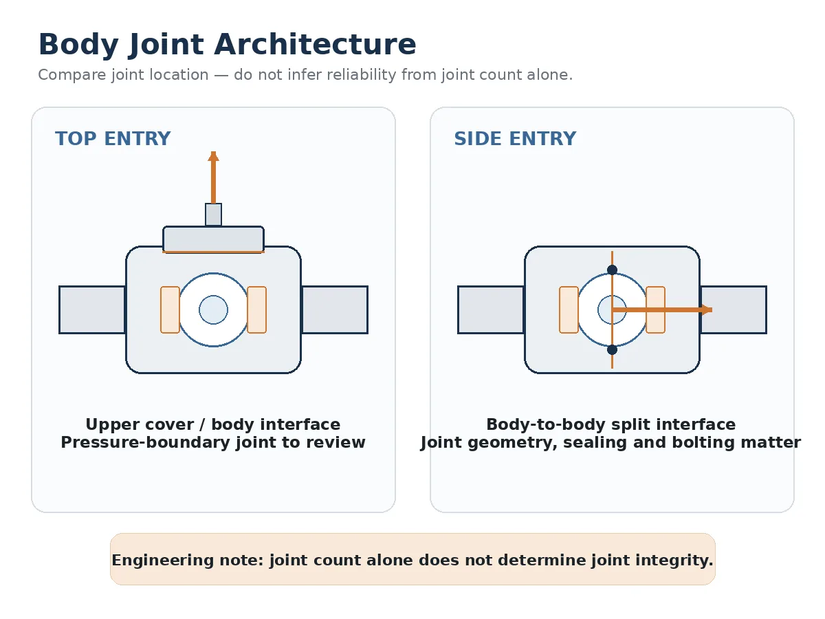
Top-Entry Cover and Body Arrangement
A top-entry configuration normally has an upper pressure-retaining closure. The review may therefore include the body, upper cover, sealing interface, fasteners, stem-related components, seat retention and machined joint surfaces.
Opening the valve means disturbing some of these interfaces. The maintenance procedure should define inspection, cleaning, replacement of specified sealing elements, controlled reassembly and the required verification before the valve returns to service.
Side-Entry Split-Body Arrangement
A side-entry valve may use one or more body-to-body interfaces to close the pressure boundary after installation of the ball and seats. Important technical-bid fields include joint location, sealing method, bolting, machining interfaces, body assembly orientation and seat retention.
For a broader explanation of bodies, covers, bolting, gaskets and other pressure-retaining interfaces, see Raymon Valve’s guide to valve body construction and pressure-boundary joints.
Why Fewer Body Joints Do Not Automatically Mean Better Reliability
Counting joints is not enough to establish pressure-boundary integrity. Joint geometry, sealing-element design, material compatibility, surface condition, bolting, assembly control, pressure-temperature conditions, thermal cycling, piping loads, inspection and pressure testing all matter.
The more useful procurement question is: What pressure-boundary joints exist, how are they sealed, and what evidence demonstrates that the proposed construction satisfies the project requirement?
In-Line Maintenance: What Does It Really Mean?
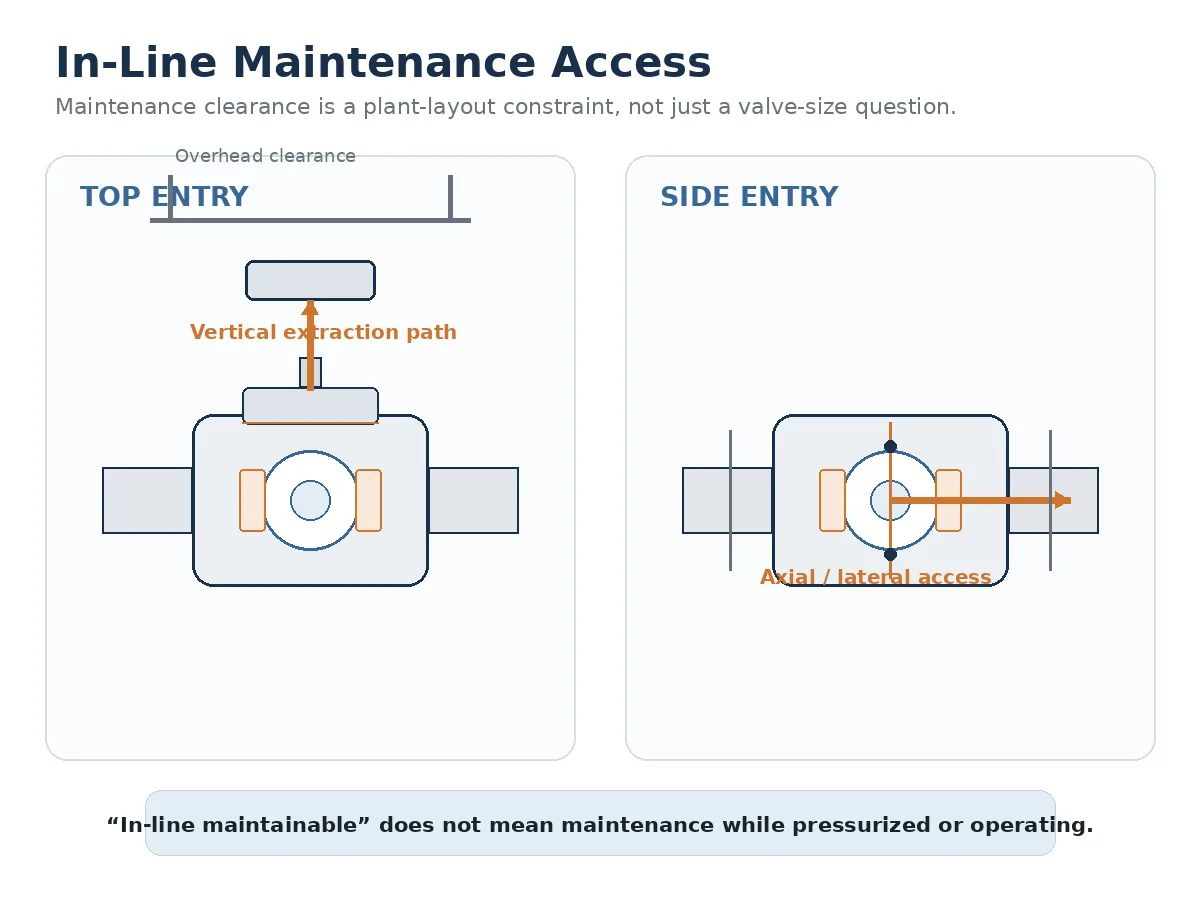
Can a Top Entry Ball Valve Be Serviced Without Removing the Body?
For a valve specifically designed for this type of maintenance, the main body can potentially remain connected to the piping while internal components are accessed from above.
That does not mean the work is performed while the valve remains pressurized or operating. Maintenance can still require site isolation procedures, depressurization, draining or purging, actuator and instrumentation disconnection, cover removal, controlled lifting, internal inspection, reassembly and post-maintenance verification.
What About Side-Entry Maintenance?
Side-entry valves should not be described as universally requiring complete valve removal. The actual method depends on the number of body pieces, end connections, piping flexibility, flange separation, spool arrangement, pipe supports, valve weight, available access and the approved manufacturer procedure.
A flanged side-entry valve installed between intentionally removable pipe sections presents a different maintenance problem from a large butt-weld valve in a tightly constrained pipeline.
What Should Be Verified Before the Valve Returns to Service?
Opening a pressure-boundary joint or removing internal components creates a return-to-service verification task. The required scope depends on what was disturbed, the approved maintenance procedure, the manufacturer’s instructions and the project or owner requirements.
- Inspect or replace disturbed gaskets, seals and other specified sealing elements.
- Verify that body-cover or body-joint fasteners have been assembled according to the approved procedure.
- Confirm that the ball, seats, stem and actuator have been reassembled in the intended configuration.
- Verify valve travel, indication and actuator operation where applicable.
- Complete the leakage, pressure or other acceptance checks required by the approved maintenance or project procedure.
- Close the maintenance and release records required before returning the valve to operating service.
A generic statement that the valve has been “reassembled” is therefore not equivalent to documented acceptance for return to service.
Maintenance Clearance May Matter More Than Installed Valve Size
A valve can fit the piping layout during construction and still be difficult to maintain later. Maintenance access should therefore be reviewed as a three-dimensional plant-layout requirement.
Top-Entry Maintenance Envelope
Depending on the design, the project may need space for actuator or gearbox removal, upper-cover lifting, ball extraction, rigging, temporary support of removed components and safe personnel access around the valve.
Side-Entry Maintenance Envelope
The installation may instead require axial flange separation, spool-piece removal, lateral lifting access, temporary pipe support and space for separating body sections or removing the complete valve.
The useful engineering question is not simply which valve is physically smaller. It is which construction can actually be maintained within the available installation, lifting and shutdown envelope.
Cavity Access, Ball Removal and Seat Inspection
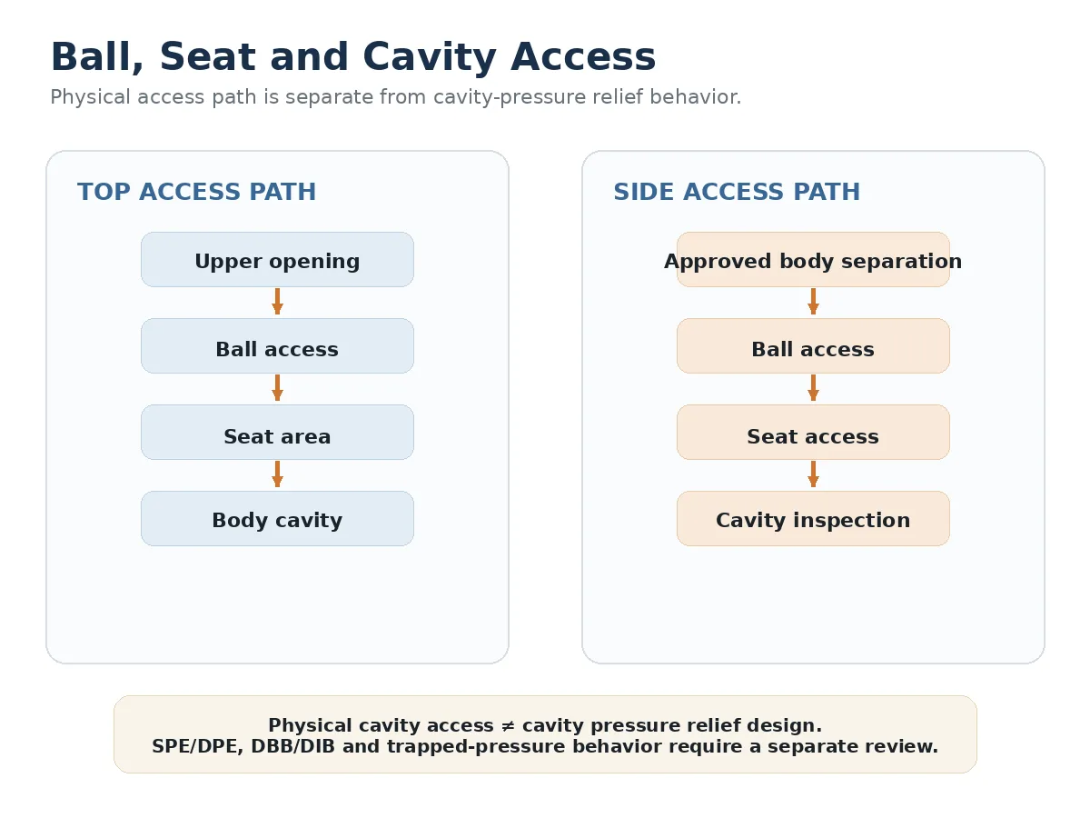
Ball and Seat Access
In a top-entry design, the ball is generally removed through the upper opening when the specific construction is designed for internal extraction. In a side-entry design, ball removal normally depends on separation of the relevant body sections or another construction-specific sequence.
Seat access can depend on seat-ring construction, retention method, seat carriers, spring arrangements where applicable, sealing elements and extraction direction. A quotation saying only “replaceable seats” does not explain whether those seats can actually be removed within the installed plant arrangement.
Physical Cavity Access Is Not the Same as Cavity-Pressure Management
Physical access for cavity inspection should be kept separate from questions about trapped cavity pressure, self-relieving seats, SPE/DPE arrangements, DBB or DIB duties.
If the project involves isolation direction and trapped-pressure behavior, review the separate Raymon Valve guide to DBB/DIB seat direction and cavity-pressure behavior.
Top Entry vs Side Entry Does Not Determine Pressure Rating
Entry arrangement is one construction variable. It is not a shortcut for determining pressure capability, temperature suitability or sealing performance.
Pressure class is also not a fixed allowable pressure independent of material and temperature. The final pressure-temperature rating must be checked against the applicable standard, material group, design temperature and exact valve construction. Normal operating pressure does not replace the project design-pressure case.
A defensible review can require confirmation of design and operating pressure, design and operating temperature, valve size, pressure class or PN, pressure-boundary materials, ball support, seat design, stem arrangement, gaskets, seals, bolting, end connections, applicable standards, testing and project-specific documentation.
Standards Context
API Specification 6D provides pipeline-valve product-standard context. The project should identify the approved edition, applicable addenda, purchaser options and any supplementary specification rather than relying on the standard number alone.
ISO 14313:2025 defines requirements for pipeline valves within its stated oil, gas and lower-carbon-energy scope and supplements API 6D 25th Edition.
ASME B16.34-2025 addresses pressure-temperature ratings, materials, dimensions, nondestructive examination, testing and marking for valves within its scope.
These standards do not make every valve with the same entry arrangement technically equivalent. The approved purchase specification, datasheet, drawings, standard editions and valve-specific design still control the final project decision.
For a broader explanation of how product, rating, dimensional, testing, fire, emissions and material standards play different roles, see Raymon Valve’s Руководство по стандартам промышленных клапанов.
When Is a Top Entry Ball Valve Worth Evaluating?
Top-entry construction deserves closer evaluation when removing the complete valve would cause significant piping disturbance, butt-weld connections make whole-valve removal undesirable, the valve or internal components require substantial lifting, internal inspection is expected during the equipment lifecycle, shutdown work must be minimized, suitable vertical maintenance clearance exists or future seat, ball and cavity access forms part of the maintenance philosophy.
These conditions provide reasons to evaluate top entry; they do not automatically make it the correct final specification.
When Does Side Entry Remain a Practical Choice?
Side-entry construction can remain practical when the piping arrangement allows controlled valve removal or body access, removable flanged spools are intentionally included, replacement rather than extensive in-situ overhaul is the maintenance strategy, lateral or axial access is available, vertical clearance is restricted or the supplier’s standard construction aligns with the approved maintenance plan.
It is therefore misleading to reduce the decision to “top entry for critical service and side entry for ordinary service.” Service severity, pressure-temperature conditions, materials, seat design, shut-off duty, test scope and maintenance access must be reviewed separately.
Normalize Lifecycle Cost Before Comparing Valve Price
Purchase price is only one part of the top-entry versus side-entry decision. Maintenance architecture can influence future piping work, lifting, spare parts, disturbed sealing elements, testing, outage work and recommissioning. The effect is project-specific, so the RFQ should normalize these cost drivers rather than assume that one entry arrangement always has the lower lifecycle cost.
| Cost / Work Element | Top Entry Review | Side Entry Review | Buyer Basis |
|---|---|---|---|
| Initial valve price | Compare the actual offered construction and included scope. | Compare the actual offered construction and included scope. | Commercial quotation after technical normalization |
| Piping / spool disturbance | Can be reduced where the approved design permits internal access while the main body remains installed. | Can increase where piping or body separation is required. | Maintenance procedure and piping layout |
| Lifting and rigging | Vertical lifting of the actuator, cover, ball or other components may be required. | Lateral handling or complete valve removal may be required depending on construction. | Component weights and lifting study |
| Replacement seals and joint materials | Review sealing elements disturbed by upper-cover opening. | Review sealing elements disturbed by body-joint separation. | Maintenance procedure and spare-parts list |
| Special tools and spares | Project and design dependent. | Project and design dependent. | Supplier maintenance tooling and recommended spares |
| Post-maintenance verification | Include the functional, leakage, pressure or other checks required after reassembly. | Include the functional, leakage, pressure or other checks required after reassembly. | Approved acceptance procedure |
| Shutdown and recommissioning | Evaluate the actual work scope and process isolation plan. | Evaluate the actual work scope and process isolation plan. | Plant maintenance strategy |
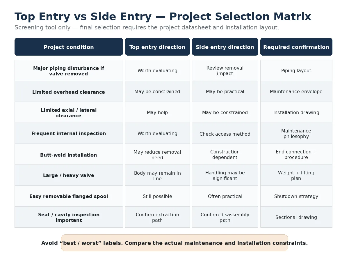
Project Selection Matrix
| Project Condition | Top Entry Direction | Side Entry Direction | Требуемое подтверждение |
|---|---|---|---|
| Removing the valve causes major piping disturbance | Worth evaluating | Review removal consequences | Piping layout and shutdown plan |
| Limited overhead clearance | May be constrained | May be practical depending on layout | Maintenance envelope |
| Limited axial or lateral dismantling space | May offer an access advantage | May be constrained | Installation drawing |
| Periodic internal inspection expected | Worth evaluating | Access sequence needs review | Maintenance philosophy |
| Butt-weld installation | In-line access may be valuable | Construction dependent | End connection and maintenance procedure |
| Large or heavy valve | Keeping the main body installed may reduce some handling work | Complete removal may require significant lifting depending on design | Valve and component weights |
| Removable flanged spool available | Still possible | Can be practical | Shutdown and spool-removal strategy |
| Seat or cavity inspection is important | Confirm upper extraction path | Confirm body-disassembly path | Sectional drawing and maintenance procedure |
What Evidence Should the Supplier Provide?
A supplier quotation becomes more useful when each major construction claim is tied to a document, drawing or procedure that can be reviewed during technical bid evaluation.
| Supplier Evidence | What It Should Confirm | What It Does Not Prove by Itself |
|---|---|---|
| Сборочный чертеж | Overall dimensions, end connections, actuator envelope and installation orientation | Internal extraction sequence |
| Разрез | Body joints, ball support, seat arrangement, stem layout and internal access path | Field maintainability without reviewing the installed layout |
| Maintenance procedure | Disassembly sequence, clearance, lifting direction, tools and component-removal route | Pressure-temperature suitability |
| Material list / MTC scope | Specified pressure-containing and trim materials and required traceability | Universal compatibility with the process medium |
| Pressure-test procedure | Planned shell and closure-test method and acceptance basis | Fire-safe, fugitive-emission or lifecycle performance unless separately required and evidenced |
| ITP | Inspection stages, hold or witness points and required deliverables | That every optional qualification test has already been performed |
| Technical deviation list | Differences between the supplier proposal and purchaser requirements | Automatic purchaser acceptance of those deviations |
| Controlled document revisions | That datasheet, GA, sectional drawing, procedures and test documents refer to the same approved configuration | Correctness of the technical content unless the documents are also reviewed |
What Should Procurement Request From the Supplier?
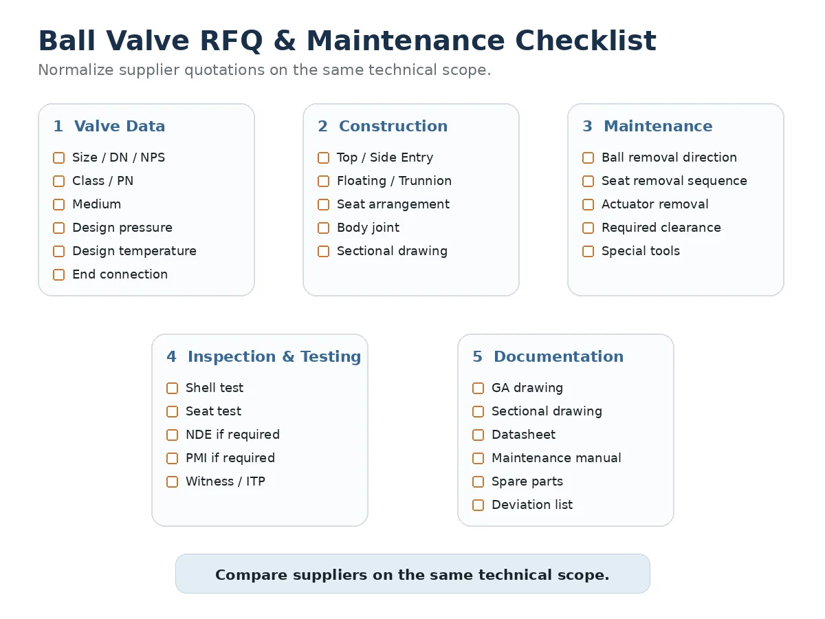
Valve Definition
State the valve function, medium, normal and design pressure, normal and design temperature, nominal size, pressure class or PN, bore requirement, entry arrangement, ball-support arrangement, end connection and operating or actuation method.
Body and Pressure-Boundary Construction
Request the GA drawing, sectional drawing, body-joint location, cover or body-separation arrangement, joint seal or gasket specification, pressure-boundary materials, bolting materials, seat retention and stem-sealing arrangement.
Информация по техническому обслуживанию
Request the maintenance procedure, ball-removal direction, seat-removal sequence, actuator-removal requirement, minimum vertical, axial and lateral clearance, valve and major-component weights where relevant, lifting arrangement, special tools and recommended spare parts.
Testing and Documentation
The RFQ should state the actual verification scope rather than using the word “tested” as a generic acceptance condition. Shell testing, closure or seat testing, functional testing, fire-safe qualification, fugitive-emission testing, NDT, PMI and project-specific inspection serve different purposes and should not be treated as interchangeable evidence.
Where required by the project, documentation can include the approved datasheet, GA drawing, sectional drawing, material list, maintenance manual, spare-parts list, inspection and test plan, test procedures, material certificates, qualification records, final test reports and technical deviation schedule.
Top Entry vs Side Entry: Final Selection Logic
The final choice should therefore be based on how the valve will be installed, isolated, opened, lifted, inspected, reassembled, verified and returned to service —not simply on whether the catalogue description says “top entry” or “side entry.”
Часто задаваемые вопросы
What is the main difference between a top entry and side entry ball valve?
The main difference is the body assembly and internal-access direction. A top-entry valve provides access through an upper opening, while a side-entry valve normally uses split or multi-piece body sections for assembly and internal access. The exact maintenance sequence still depends on the valve-specific construction.
Can a top entry ball valve be maintained without removing it from the pipeline?
Some top-entry designs allow internal inspection or repair while the main body remains connected to the piping. This still requires approved isolation and depressurization, sufficient lifting clearance, the manufacturer’s maintenance procedure and the required return-to-service verification.
Does a top entry ball valve automatically have fewer leakage risks?
No. The body-joint arrangement may differ from a split-body valve, but joint count alone does not establish leakage performance. Joint design, sealing materials, machining, bolting, assembly, operating conditions, inspection and testing must also be evaluated.
Are side entry ball valves only suitable for lower-pressure service?
No. Entry arrangement alone does not establish pressure capability. Pressure-temperature suitability depends on the applicable standard, material group, design temperature, complete valve construction and manufacturer-confirmed rating.
Is a top entry ball valve always trunnion mounted?
No. Top entry describes body assembly and access, while floating or trunnion-mounted describes ball support. The two design decisions should be specified and verified separately from the sectional drawing.
What information should be included in a top-entry vs side-entry ball valve RFQ?
Provide the valve duty, medium, normal and design pressure, normal and design temperature, size, pressure class, bore, end connection, materials, ball support, seat requirements, installation layout, maintenance clearance, actuation, testing and documentation requirements. Ask the supplier to return controlled drawings, a maintenance procedure and a technical deviation list.
Request Ball Valve Construction & Maintenance Review
Send the valve duty, medium, normal and design pressure, normal and design temperature, size, pressure class, end connection, required ball support, seat arrangement, installation or GA drawing, available vertical and lateral maintenance clearance, shutdown philosophy, actuation requirement, testing scope, quantity and project specification.
The technical review should identify the proposed construction, body-joint arrangement, internal-access route, required maintenance clearance, testing and documentation scope, and any technical deviations before top-entry and side-entry quotations are treated as directly comparable.
Submit Your Ball Valve Datasheet Russian
  English
  German
  Arabic
  French
  Spanish
  Italian
  Portuguese