
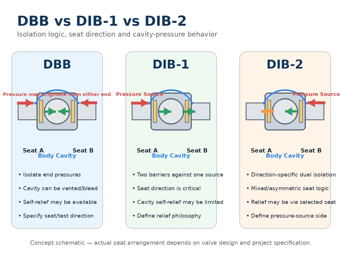
Double block and bleed (DBB) and double isolation and bleed (DIB) define different isolation duties. DBB addresses sealing against pressure from both valve ends while the cavity between the seats can be vented or bled. DIB requires two sealing barriers against one defined pressure source. The correct choice therefore depends on pressure-source direction, seat behavior, trapped-cavity pressure, vent or relief philosophy, and the test method used to prove the specified function.
DBB vs DIB: What Is the Practical Difference?
The practical difference is not simply whether the valve has two seats. A DBB requirement and a DIB requirement ask the valve to perform different isolation functions, so the purchaser must define what is being isolated, where pressure can originate, and what must remain depressurized during maintenance or verification.
Краткий ответ: use DBB or DIB terminology only after the isolation duty is clear. Then verify Seat A and Seat B sealing direction, body-cavity pressure behavior, vent and drain scope, and the acceptance test. A supplier quotation that says only “DBB” or “DIB” is not enough for technical comparison.
| Пункт рассмотрения | DBB | DIB |
|---|---|---|
| Primary isolation objective | Seal against pressure associated with both valve ends while providing cavity bleed or vent capability | Provide two sealing barriers against one defined pressure source |
| Two seats present | Да | Да |
| Two barriers against one source | Not the defining requirement | Yes, subject to the specified configuration and pressure direction |
| Seat direction | Важно | Critical |
| Cavity-pressure management | Must be reviewed | Must be explicitly defined |
| Acronym alone sufficient for RFQ approval? | No | No |
Standards and Project Specification Context
API Specification 6D provides the product-standard context for pipeline and piping valves, but a standard title alone does not close the project requirement. The purchaser still needs to confirm the contract edition, applicable addenda, purchaser options, valve construction, test scope and order-specific acceptance criteria.
API currently lists Specification 6D, 25th Edition with subsequent addenda including Addendum 3 issued in March 2025. Verify the project-approved edition and amendments on the API 6D updates page.
IOGP JIP33 S-562 is an example of a purchaser supplementary specification for API 6D ball valves. Its December 2024 requirements address cavity relief, vents and drains and illustrate how an owner or EPC can add requirements beyond the base product standard. These purchaser requirements should not be presented as universal API 6D requirements for every valve or project. See the IOGP JIP33 S-562 supplementary specification.
For supported-ball designs, the proposed seat loading, bore, cavity-relief path, drains and operator requirements should be checked against the actual datasheet and drawing. Raymon Valve’s шаровому крану с цапфой resource treats those items as project-defined review points rather than assumptions.
DBB and DIB Are Functional Requirements, Not Just SPE/DPE Labels
DBB and DIB describe isolation functionality. SPE and DPE are commonly used to describe seat pressure-response behavior. The concepts are related, but they are not interchangeable definitions.
A manufacturer may use SPE, DPE or a mixed seat arrangement to achieve the required function. The purchaser should therefore verify the proposed seat direction and pressure behavior on the sectional drawing instead of approving the valve from the seat acronym alone.
A typical RFQ mistake occurs when the datasheet states only “DBB required” while different bidders assume different seat arrangements. The commercial quotations may look comparable, but the technical scope is not. The correction is to define the pressure-source cases, seat directions, cavity-relief philosophy and directional test before comparing price.
Minimum Data Required Before Selecting DBB or DIB
The seat arrangement should not be approved until the project has defined the service conditions that control isolation and cavity behavior.
| Decision Field | Почему это важно | What the RFQ Should Confirm |
|---|---|---|
| Запорная функция | Defines whether one or two barriers are required against the relevant pressure source | DBB, DIB-1, DIB-2 or another project-defined isolation requirement |
| Pressure-source direction | Determines which seat must act as the primary or secondary barrier | Normal, reverse, shutdown, depressurization and maintenance scenarios |
| Среда и фазовое состояние | Affects cavity-pressure behavior and containment consequences | Gas, liquid, mixed phase, composition, solids and any hazardous-service constraints |
| Normal and design pressure | Pressure class alone does not define the actual differential or service pressure | Normal, design and credible differential-pressure cases |
| Нормальная и расчетная температура | Temperature affects rating, seat materials and trapped-liquid expansion risk | Normal, maximum, minimum and relevant thermal-cycle conditions |
| Seat directionality | Determines whether the required barrier exists for the defined pressure case | Seat A and Seat B sealing direction on the approved drawing |
| Cavity-pressure philosophy | Prevents the isolation arrangement from creating an unmanaged trapped cavity | Internal self-relief, approved external relief or another project-defined method |
| Acceptance testing | Demonstrates the specified function rather than only general valve tightness | Pressure direction, leakage criterion, hold/witness point and required record |
Single Piston Effect Seat
A single piston effect seat is commonly arranged so that line-side pressure energizes the seat toward the ball while excess cavity pressure can, under the required differential condition, create a relief path toward an adjacent line.
The actual relief direction and the differential pressure needed to move the seat are design-specific. They should be confirmed from the supplier’s approved drawing and design data rather than inferred from the term SPE alone.
Double Piston Effect Seat
A DPE seat is commonly arranged so that pressure acting from either relevant side can energize the seat toward the ball. That behavior can support a second seating barrier against a defined pressure source, but it may also restrict cavity self-relief through that seat.
This is why seat isolation and cavity-pressure protection must be reviewed together. A more restrictive seat arrangement is not automatically a better system solution if the trapped-cavity pressure path has not been defined.
DBB vs DIB-1 vs DIB-2
Where the project specification distinguishes DIB-1 and DIB-2, the required configuration should be stated explicitly. The labels affect which pressure source must be isolated, how the two seats act as barriers and how trapped body-cavity pressure is managed.
| Конфигурация | Isolation Objective | Seat Direction Sensitivity | Cavity Relief Review | RFQ Requirement |
|---|---|---|---|---|
| DBB | Isolation associated with pressures at both valve ends with cavity bleed capability | Важно | Confirm the actual internal relief path and receiving side | Define end-pressure cases, bleed function and seat test |
| DIB-1 | Two seating barriers against one defined pressure source | Critical | Explicit review required because the isolation arrangement can restrict seat-based cavity relief | Define pressure-source side, both barriers and cavity-relief feature |
| DIB-2 | Direction-specific dual isolation using the proposed seat arrangement | Critical | Confirm whether relief is available through the selected seat and under which pressure case | Define which side provides the required dual barrier and how the reverse case behaves |
Pressure Source Is Not the Same as Normal Flow Direction
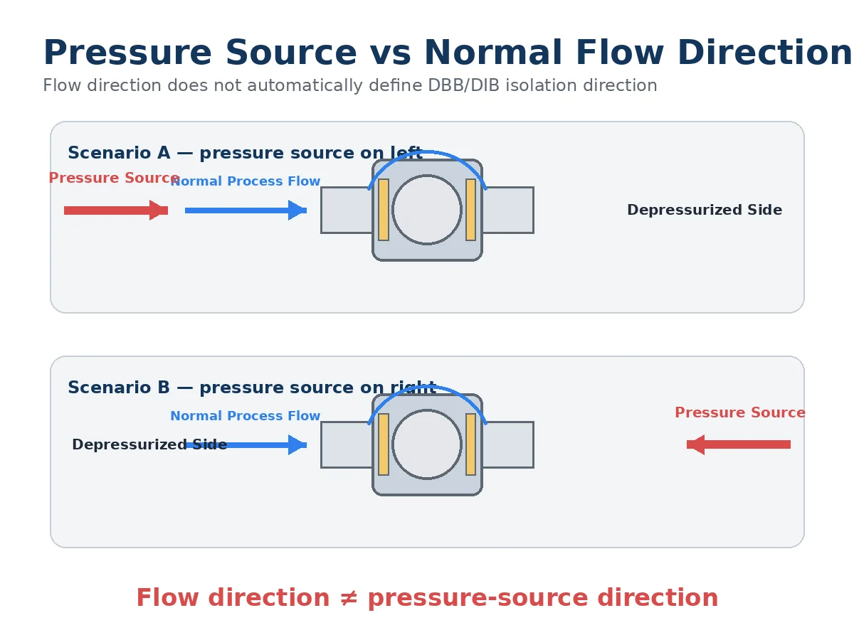
Normal process-flow direction does not automatically define the pressure-source direction used for isolation verification. Shutdown, depressurization, maintenance, pressure reversal or equipment isolation can create a pressure source from either valve end.
A recurring drawing-review problem is that the P&ID or line list shows normal flow, but the valve datasheet does not identify which side can remain pressurized during maintenance. The corrective action is to define each credible pressure-source case and then check Seat A and Seat B against those cases.
Why Body-Cavity Pressure Matters
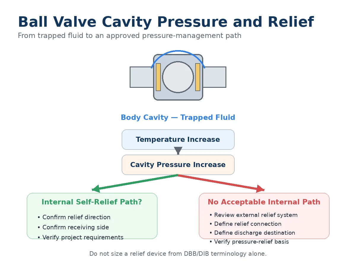
When a ball valve closes, process fluid can become trapped between the seats. If trapped liquid is heated, thermal expansion can raise body-cavity pressure. Whether that pressure can discharge through one seat depends on the actual seat design and the pressure conditions on the adjacent line.
The engineering question is therefore not only “Can the valve isolate?” but also “Where can trapped cavity pressure go under each credible condition?” The answer belongs in the valve design review and, where relevant, in the piping-system pressure-relief review.
Self-Relieving Seats vs External Cavity Relief
Internal Self-Relieving Seat
Where the selected seat design provides an internal relief path, engineers should verify the relief direction and confirm that the receiving side can accept the relieved fluid under the relevant operating case.
External Cavity Relief
If the seat arrangement does not provide an acceptable internal path, a project-approved external cavity-relief feature or system may be required. The review should define the relief connection, pressure basis, discharge destination, process-fluid containment and responsibility between the valve supplier and the piping-system designer.
DBB/DIB terminology alone is not enough to size a relief device or prove the system pressure-protection design.
Vent, Bleed, Drain and Cavity Relief Are Different Functions
| Особенность | Main Purpose | Typical Engineering Use | Automatic Cavity Overpressure Protection? |
|---|---|---|---|
| Vent | Release gas or access cavity pressure | Depressurization, verification or maintenance access | Not necessarily |
| Отвод | Remove accumulated liquid | Maintenance or cavity draining | No |
| Bleed | Depressurize the space between isolation barriers | Isolation verification or maintenance | Not necessarily |
| Cavity relief | Manage unacceptable trapped body-cavity pressure | Pressure-protection function | Depends on the approved design |
How Should DBB or DIB Function Be Verified?
An isolation designation is useful only if the required function can be demonstrated by an appropriate test. Shell testing, closure or seat leakage testing and directional DBB/DIB functional verification serve different purposes and should not be treated as interchangeable.
Depending on the governing specification and approved procedure, verification may include applying pressure from a defined valve end, monitoring the body cavity or opposite side, checking leakage across a specified seat and repeating the test from another pressure direction when required.
A typical FAT review issue occurs when the valve passes a general seat test but the procedure never reproduces the pressure direction required by the project DIB duty. The evidence is therefore insufficient even though the test itself may have been performed correctly. The remedy is to map each required barrier to a defined pressure step and acceptance criterion before the inspection and test plan is approved.
For a broader review of shell, closure and functional test scope, see Raymon Valve’s valve pressure testing and seat-test requirements guide. For product, rating, dimensional and test-standard boundaries, review the industrial valve standards guide.
Pipeline Specification: Do Not Write Only “DBB Required”
A description such as “API 6D trunnion ball valve, DBB required” still leaves important engineering decisions open. A comparable RFQ should close the following fields before technical bid evaluation.
Service Conditions
- Medium, composition, phase and solids where relevant
- Normal pressure and design pressure
- Normal temperature, design temperature and credible low-temperature condition
- Possible trapped-liquid condition
- Normal, reverse, shutdown and maintenance pressure-source scenarios
Valve Construction
- Valve type and supported-ball construction where required
- Nominal size and required bore
- Pressure class or rating basis, checked with the applicable material group and temperature
- End connection and dimensional requirements
- Body, trim, seat, stem sealing, packing/gasket and bolting requirements where applicable
Isolation Requirement
- DBB, DIB-1 or DIB-2 requirement
- Defined pressure-source direction for each isolation scenario
- Required primary and secondary seating barriers
- Seat directionality and proposed SPE/DPE terminology where used
- Required leakage or shutoff acceptance criterion
Cavity Management
- Internal cavity self-relief philosophy
- Permitted relief direction and receiving side
- External cavity-relief requirement where applicable
- Body vent and drain scope
- Bleed connection and discharge destination
Testing and Documentation
- Applicable product standard and project-approved edition
- Purchaser supplementary specification
- Directional seat-test sequence
- Leakage acceptance requirement
- DIB functional verification where applicable
- Valve sectional and seat-direction drawing
- ITP hold/witness/review points where required
- Material traceability, test reports and technical deviation schedule
Raymon Valve’s шаровой кран API 6D resource also treats bore, seat arrangement, cavity behavior and documented testing as order-specific review items rather than assumptions from the product name.
DBB / DIB RFQ Normalization Matrix
Procurement teams should normalize supplier quotations against the engineering requirement instead of assuming that every bid using the same acronym proposes the same construction.
| Пункт запроса информации | Поставщик А | Поставщик Б | Supplier C | Deviation / Open Point |
|---|---|---|---|---|
| DBB / DIB function | ||||
| DIB type, if applicable | ||||
| Seat A sealing direction | ||||
| Seat B sealing direction | ||||
| Pressure-source cases | ||||
| SPE / DPE terminology | ||||
| Cavity self-relief path | ||||
| External relief scope | ||||
| Vent / drain / bleed scope | ||||
| Directional seat testing | ||||
| Leakage acceptance | ||||
| Required drawings and records | ||||
| Технические отклонения |
Supplier Technical Evaluation: What Evidence Should Be Reviewed?
Two suppliers can both quote a DBB or DIB ball valve while proposing different seat arrangements, cavity-relief methods and test procedures. The purchaser should compare the evidence behind the designation, not only the designation itself.
| Supplier Evidence | What It Should Confirm | Technical Review Question |
|---|---|---|
| Разрез | Actual seat arrangement, body cavity and relevant internal features | Does the proposed construction match the required isolation duty? |
| Seat-direction drawing or marked sectional | Which pressure direction each seat is intended to seal against | Are every defined pressure-source case and both barriers traceable? |
| Cavity-relief description | Internal or external relief path and discharge direction | Where does trapped cavity pressure go under each credible condition? |
| Seat test procedure | How isolation performance will be demonstrated | Does the pressure direction reproduce the required DBB/DIB duty? |
| Datasheet / technical offer | Materials, rating basis, construction, accessories and open assumptions | Are all deviations from the RFQ clearly declared? |
| ITP / witness plan where required | Inspection, test and document review points | Are purchaser hold/witness points identified before evidence becomes inaccessible? |
Common DBB / DIB Failure Modes and Verification Points
| Potential Issue | Likely Specification Cause | Evidence to Check | Corrective Direction |
|---|---|---|---|
| Required second barrier is unavailable in the defined pressure case | DIB acronym used without defining pressure direction | Seat A / Seat B direction and sectional drawing | Define pressure source and barrier sequence before approval |
| Unexpected body-cavity pressure rise | Seat arrangement restricts internal relief and no alternate path is defined | Cavity-relief description and piping relief philosophy | Resolve the relief path through design review; do not assume a manual vent is sufficient |
| Valve passes a general seat test but does not prove the specified isolation duty | Test procedure does not reproduce the project pressure direction | Test steps, pressure side, monitored cavity and acceptance criterion | Revise the functional verification procedure before FAT |
| Supplier bids are commercially compared but technically non-equivalent | RFQ specifies only DBB or DIB without construction and test details | Normalized seat arrangement, relief scope and documentation | Close technical deviations before commercial normalization |
| Vent connection is treated as automatic overpressure protection | Vent, bleed and cavity-relief functions are combined into one line item | P&ID, valve drawing and relief design basis | Separate the purpose and discharge path of each connection |
When May DBB Be Appropriate?
DBB may fit a project where the required duty is to isolate pressure associated with both valve ends and where the intermediate cavity can be safely vented or bled for verification or maintenance.
That does not make DBB a universal default. Final suitability still depends on leakage consequences, pressure-source scenarios, seat behavior, cavity-pressure management, test requirements and the governing project specification.
When Should DIB Be Evaluated?
DIB should be evaluated where the project explicitly requires two seating barriers against one defined pressure source. The engineering value comes from the required barrier arrangement, not from the acronym itself.
DIB should not automatically be described as “safer” or “better” than DBB. The complete system must still manage cavity pressure, venting, testing and downstream maintenance conditions.
Common DBB / DIB Specification Mistakes
- Writing only “DBB required” or “DIB required” without defining the isolation duty.
- Assuming SPE/DPE terminology alone proves the required function.
- Using normal process-flow direction as the only pressure-source definition.
- Ignoring trapped body-cavity pressure and thermal expansion scenarios.
- Treating a manual vent as automatic pressure-relief protection.
- Using pressure class as if it were a fixed allowable service pressure.
- Accepting a general seat test without confirming the directional isolation case.
- Comparing supplier prices before seat arrangement, relief scope and testing have been normalized.
What Should the Supplier Drawing and Document Package Show?
- Valve sectional drawing with Seat A and Seat B clearly identified
- Sealing-direction arrows or equivalent seat-function description
- Body-cavity configuration
- Vent, drain and bleed locations
- Cavity-relief philosophy and discharge direction
- External relief connection where applicable
- Applicable test procedure and directional test sequence
- Material and order-specific datasheet information
- Technical deviation list and inspection/documentation scope
During document review, a common problem is that the datasheet, sectional drawing and test procedure were prepared by different teams and do not describe the same seat direction. The reviewer should resolve that inconsistency before manufacturing or FAT rather than trying to interpret it after the valve has been completed.
DBB or DIB: A Practical Selection Sequence
- Define the isolation duty. Identify what must be isolated and from which pressure source.
- Define the required barriers. Determine whether the project needs two sealing barriers against one source.
- Identify pressure scenarios. Review normal, reverse, shutdown, maintenance and trapped-cavity conditions.
- Define seat directionality. Establish which seat must seal under each credible case.
- Define cavity-pressure management. Confirm the approved internal or external relief path.
- Separate vent, drain and bleed functions. State the purpose and discharge route for each connection.
- Define acceptance testing. Make the test reproduce the required isolation duty and leakage criterion.
- Normalize supplier evidence. Compare drawings, procedures, deviations and documentation before commercial evaluation.
Часто задаваемые вопросы
What is the main difference between DBB and DIB ball valves?
DBB addresses sealing against pressure from both valve ends while the intermediate cavity can be vented or bled. DIB requires two sealing barriers against one defined pressure source. The final configuration still depends on seat direction, cavity-pressure management and the project test requirement.
Is DBB the same as a ball valve with two SPE seats?
No universal seat formula should be used as the definition. Two SPE seats are a common implementation in some trunnion-mounted designs, but the DBB function and the actual seat arrangement should be verified separately.
What is the difference between DIB-1 and DIB-2?
Both address dual isolation against a defined pressure source, but the required seat arrangement and pressure direction differ. The purchaser should state the required DIB type, pressure-source side and cavity-relief philosophy rather than using “DIB” alone.
Why can DIB affect ball valve cavity pressure?
A seat arrangement that provides an additional barrier can also restrict the path available for trapped cavity pressure. If liquid can be trapped and heated, the approved internal or external relief path must be reviewed with the isolation design.
Does a body vent replace a cavity-pressure relief system?
Not automatically. A body vent can provide access for intentional depressurization or verification, but it is not by itself proof of an automatic pressure-protection function.
What information should be included when ordering a DBB or DIB ball valve?
Provide the medium and phase, normal and design pressure, normal and design temperature, valve size, rating basis, end connection, pressure-source scenarios, required DBB/DIB function, seat direction, cavity-relief philosophy, vent/drain/bleed scope, leakage criterion, test requirements and purchaser specification.
Pressure class alone does not define allowable service pressure. Final suitability depends on the actual valve type, size, materials, temperature, medium, pressure cases, seat design, manufacturing route, test scope and project specification.
Request DBB / DIB Ball Valve Specification Review
Before requesting a final quotation, provide the service medium and phase, normal and design pressure, normal and design temperature, valve size and pressure class, end connection, pressure-source scenarios, required DBB / DIB-1 / DIB-2 function, seat direction if already defined, cavity-relief philosophy, vent/drain/bleed scope, leakage criterion, required tests and applicable purchaser specification.
The technical review should close the seat arrangement, cavity-pressure management, testing and documentation scope before supplier prices are treated as directly comparable.
Submit Your Valve Datasheet / RFQFor broader project-defined ball-valve selection, review the Raymon Valve Ball Valves category.
 Russian
  English
  German
  Arabic
  French
  Spanish
  Italian
  Portuguese