
Control Valve Noise: Aerodynamic vs Hydrodynamic Noise, Velocity, Trim Selection and Piping Effects
Control valve noise is best diagnosed by identifying the physical mechanism first: aerodynamic noise is mainly associated with compressible gas or vapor flow, while hydrodynamic noise comes from liquid turbulence and can increase when cavitation occurs. The engineering decision is not only which trim to use, but also which operating case governs, whether outlet velocity or downstream piping contributes, and what calculation evidence is required before technical approval. This guide supports mechanism screening, trim and piping review, RFQ preparation and supplier comparison.
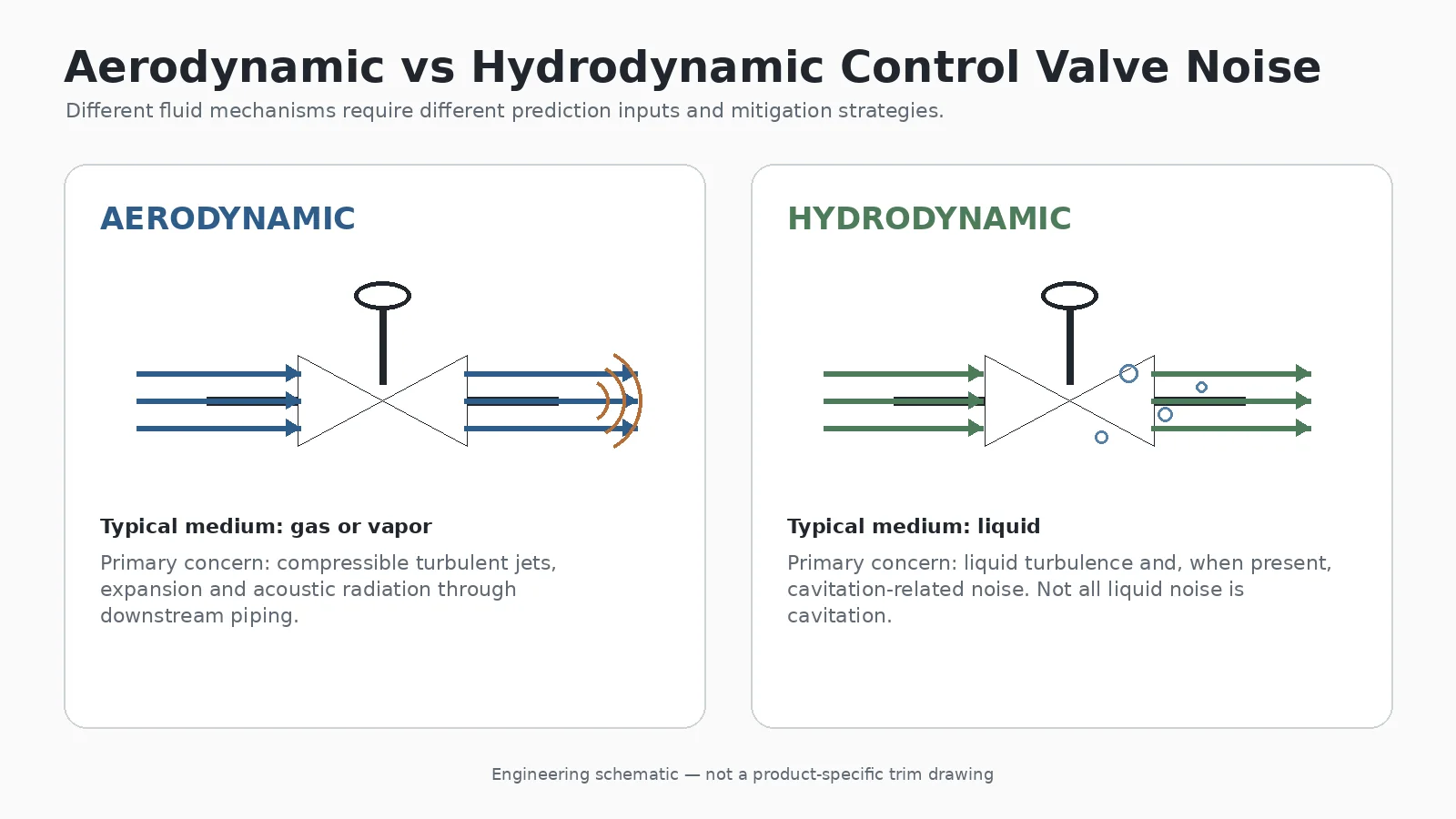
What Actually Causes Control Valve Noise?
A control valve dissipates pressure energy as the fluid passes through a restricted flow path. The fluid accelerates, changes direction and forms turbulent structures; part of the available energy can then appear as vibration and acoustic energy. A useful review therefore separates three questions: what mechanism is generating the noise, which operating case is controlling, and whether the dominant source is inside the valve, in the downstream piping or in the structural response of the installed system.
Mechanical Noise
Mechanical noise can originate from looseness, resonance or unstable movement of valve components and connected piping. Trim vibration, stem or plug instability, actuator-related vibration and piping support problems should not automatically be diagnosed as aerodynamic or hydrodynamic noise. If the sound changes sharply with valve travel or is accompanied by localized vibration, field evidence should be collected before a trim change is specified.
Aerodynamic Noise
Aerodynamic noise is associated primarily with compressible gas or vapor flow. High-energy turbulent jets and downstream expansion can generate acoustic energy. Pressure ratio, flow rate, fluid properties, valve style, trim geometry, valve travel and downstream piping all influence the predicted result.
Hydrodynamic Noise
Hydrodynamic noise is produced by liquid flow. Normal turbulent liquid flow can generate noise without cavitation. When local pressure falls sufficiently for vapor to form and pressure subsequently recovers enough for bubbles to collapse, cavitation can add noise, vibration and damage risk. Cavitation is therefore an additional hydrodynamic noise mechanism, not the definition of hydrodynamic noise itself.
Aerodynamic vs Hydrodynamic Control Valve Noise
| Engineering Question | Aerodynamic Noise | Hydrodynamic Noise |
|---|---|---|
| Typical fluid | Gas or vapor | Liquid |
| Main mechanism | Compressible turbulent jets and pressure-energy release | Liquid turbulence and, where present, cavitation |
| Important inputs | Flow, P1, P2, temperature, gas properties, valve geometry and piping | Flow, P1, P2, temperature, liquid properties, vapor pressure, valve recovery behavior and piping |
| Velocity concern | Internal jet and downstream gas velocity | Liquid velocity plus possible cavitation or two-phase effects |
| Typical review direction | Low-noise trim, staged reduction, diffuser and piping review | Hydraulic sizing, pressure-recovery review and anti-cavitation strategy where applicable |
| Can downstream piping matter? | نعم | نعم |
Aerodynamic Noise in Gas and Vapor Service
When a compressible fluid passes through a throttling restriction, part of the available pressure energy is converted into kinetic energy. High-velocity turbulent jets can form downstream of the trim, so noise severity cannot be inferred from differential pressure alone. Relevant inputs can include inlet and outlet pressure, flow, gas properties, temperature, valve construction, travel, downstream pipe diameter and adjacent expanders or fittings.
Hydrodynamic Noise in Liquid Service
Liquid-service noise requires a different review. Normal turbulence can generate hydrodynamic noise without phase change. If local pressure conditions allow vapor formation and subsequent bubble collapse, cavitation becomes an additional mechanism. For a focused review of pressure recovery, bubble collapse and persistent downstream vapor, see cavitation and flashing behavior in liquid service .
Noise Mechanism Screening: What Can Field Evidence Tell You?
| Field Evidence | Likely Direction | Do Not Conclude Yet |
|---|---|---|
| Noise rises sharply with gas pressure reduction | Aerodynamic mechanism may dominate | Do not select trim before sizing and noise prediction. |
| Liquid noise occurs without confirmed cavitation evidence | Normal hydrodynamic turbulence remains possible | Do not automatically classify the condition as cavitation. |
| Vibration is strongest at the valve body or trim area | Valve-side excitation may dominate | Confirm whether the response changes with process conditions. |
| Noise or vibration peaks near an elbow or reducer | Downstream piping may be contributing | Do not assume the valve alone is the source. |
| Noise appears mainly at one operating case | That case requires separate review | Maximum flow is not automatically the controlling case. |
Field Scenario: Noise Appears Only Near One Valve Position
A common field issue is a valve that sounds acceptable through most of its travel but becomes noisy or vibrates within a narrow operating region. The cause may be a severe local throttling condition, an unfavorable pressure ratio, trim instability or a piping response that is only excited at that condition. The practical response is to record actual flow, P1, P2, temperature and valve travel at the noisy point, compare those values with the approved sizing cases, and inspect downstream fittings and supports before changing the trim.
Why Velocity Matters — and Why One Universal Limit Does Not Work
Velocity is an important control-valve design variable, but it cannot be reduced to one universal acceptance number. Its significance depends on where velocity is evaluated, fluid phase, density, pressure, temperature, valve geometry, downstream pipe diameter and the project-specific acceptance basis. A published or quoted velocity should therefore be tied to a defined location and operating case.
Internal Trim Velocity vs Downstream Pipe Velocity
Inside the valve, local acceleration through restricted passages can contribute to jet formation, turbulence, acoustic generation, erosion exposure and, in liquid service, cavitation risk. Downstream velocity is a separate system-level issue: a high outlet velocity can increase turbulence, piping vibration, erosion exposure and acoustic transmission at expanders, reducers and elbows.
Which Operating Case Controls?
Maximum flow is not automatically the worst noise condition. Another case can impose a more severe pressure ratio, smaller valve opening or different phase behavior. Minimum, normal, maximum and relevant transient conditions should therefore be checked independently.
| Operating Case | ما يجب التحقق منه | لماذا هو مهم |
|---|---|---|
| الحد الأدنى للتدفق | Travel, differential pressure, pressure ratio and stability | A small opening can create severe local throttling. |
| التدفق الطبيعي | Control performance and baseline noise | Provides the main continuous operating reference. |
| أقصى تدفق | Outlet velocity, required Cv and downstream condition | May govern capacity or system velocity. |
| Startup or shutdown | Temporary P1, P2, temperature and phase behavior | Can create conditions not present during normal operation. |
| Abnormal or upset condition | Project-defined transient inputs | May require separate acceptance or equipment review. |
How Pressure Drop Influences Control Valve Noise
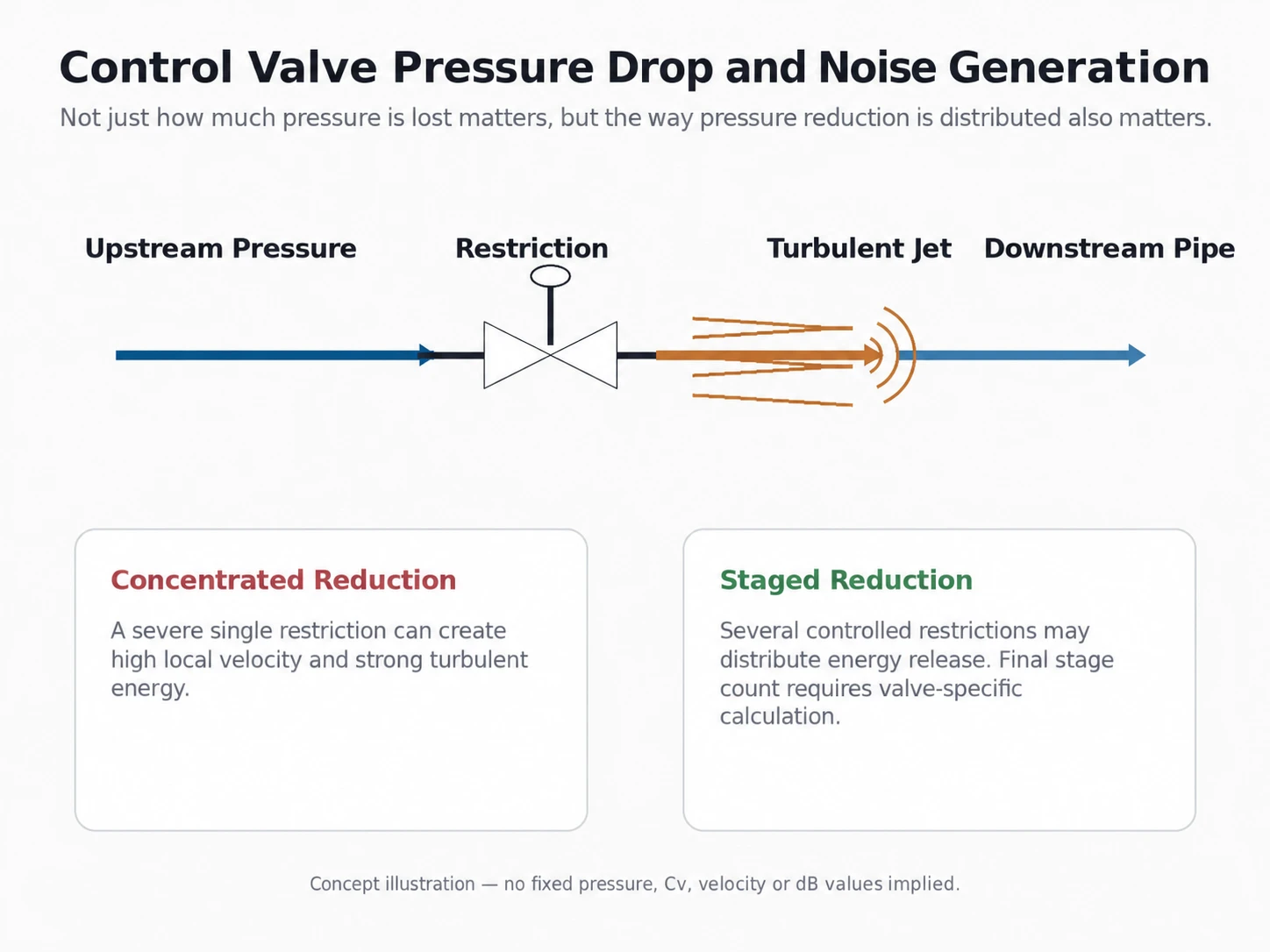
Differential pressure indicates how much pressure energy the valve must dissipate, but total P1 minus P2 does not fully describe the internal flow field. Two valves exposed to the same overall differential pressure can behave differently because their trim geometry, pressure recovery, flow paths and staging differ.
Concentrated Pressure Reduction
A severe single restriction can produce high local velocity and intense turbulent energy. The resulting acoustic response depends on the fluid, valve geometry and downstream condition.
Staged Pressure Reduction
Multi-stage trim distributes the required pressure reduction through several restrictions. For appropriate services, this can reduce individual jet severity and redistribute energy release.
When Should Low-Noise Trim Be Considered?
Low-noise trim should be treated as an engineering response to a defined service condition, not as a catalog upgrade selected whenever an RFQ mentions noise. Review the fluid phase, required flow capacity, operating cases, valve travel, downstream piping, project noise criterion, maintenance conditions and any relevant solids or fouling tendency. For product-level configurations, review low-noise control valve constructions against the complete service data rather than selecting from the product name alone.
The underlying control valve sizing inputs and calculation basis should be established before a trim arrangement is approved. A nominal line size or pressure class does not establish required Cv, travel or acoustic performance.
Multi-Hole or Multi-Path Trim
Some low-noise constructions divide the flow into multiple smaller passages rather than allowing one or a few concentrated jets. The engineering objective may include redistribution of energy, reduced individual jet intensity and modified acoustic generation.
Multi-Stage Trim
Multi-stage designs can distribute pressure reduction through several controlled restrictions. They may be appropriate when a severe single-stage reduction would create unacceptable aerodynamic or hydraulic conditions, but the stage count and geometry remain valve- and case-specific.
Anti-Cavitation Trim Is Not Automatically the Same as Aerodynamic Low-Noise Trim
Both designs may use cages, drilled passages or multiple stages, but their engineering objectives differ. Anti-cavitation trim manages liquid pressure behavior and harmful vapor collapse. Aerodynamic low-noise trim addresses acoustic generation in compressible flow. The proposal should state which mechanism is being controlled rather than relying on a generic “severe-service” or “multi-stage” label.
Trim Is Selected Against a Mechanism, Not a Marketing Label
A technical bid should explain what mechanism the proposed trim addresses, how pressure reduction is distributed, which operating cases were calculated, what downstream condition was assumed and whether the proposed trim remains compatible with required Cv, travel, shut-off duty, fluid cleanliness, erosion or fouling risk and maintenance needs.
RFQ Scenario: “Low-Noise Trim Included” Is Not Enough
A typical RFQ mistake occurs when one bidder quotes a standard trim and another simply states “low-noise trim included,” but neither proposal identifies the operating case, prediction method, downstream pipe basis or predicted travel. The apparent technical difference cannot be evaluated until both bidders use the same process cases and assumptions. Normalize the inputs first, then compare sizing, predicted noise, trim concept, outlet condition and deviations.
Valve Trim vs Piping Treatment
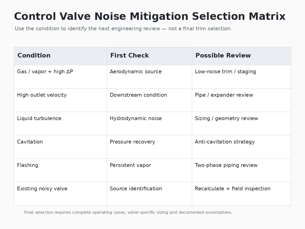
A control valve noise problem may involve three engineering layers: generation at the valve, transmission through downstream piping and structural response of the installed piping system. Treating only the transmission path can reduce radiated noise without correcting the underlying hydraulic or aerodynamic source.
| Observed Condition | Primary Review | Possible Engineering Direction |
|---|---|---|
| Strong aerodynamic source at the valve restriction | Valve / trim | Low-noise trim, staging or diffuser review |
| High outlet velocity | Valve and piping | Outlet sizing, expander and downstream piping review |
| تجويف السائل (Cavitation) | Hydraulic source | Pressure-recovery and anti-cavitation review |
| Persistent flashing downstream | System and piping | Two-phase velocity, material and piping review |
| External noise remains after valve-side treatment | Transmission path | Pipe wall, insulation, silencer or layout review |
| Vibration concentrates near a fitting or support | Structural response | Geometry, supports, excitation and resonance review |
How Downstream Piping Affects Control Valve Noise
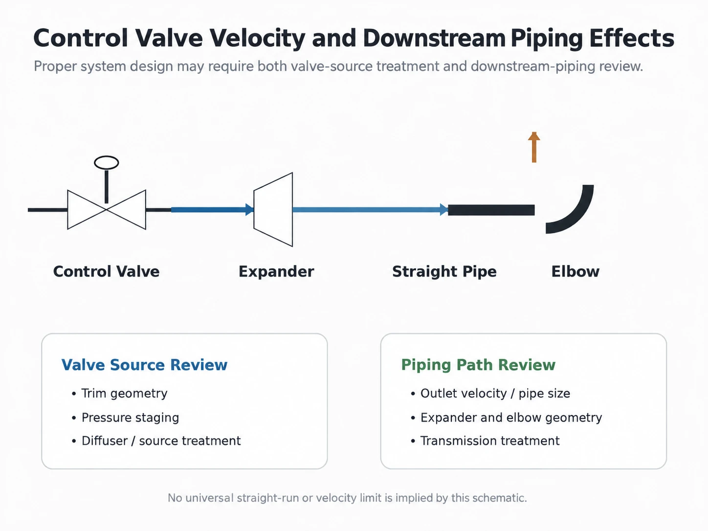
Downstream Pipe Diameter
The downstream pipe determines the velocity into which the valve discharge expands. A small line can maintain high gas, liquid or two-phase velocity after the fluid leaves the valve. Where valve outlet and line sizes differ, the expander and downstream pipe should be represented in the review.
Reducers and Expanders
Changes in flow area affect velocity and turbulence. Their geometry and location can also influence acoustic behavior. The installed arrangement should therefore match the assumptions used in sizing and noise prediction.
Elbows Near the Valve
A high-energy jet entering a nearby elbow may increase local turbulence, vibration or erosion exposure. A universal straight-pipe distance should not be imposed unless it is supported by the applicable method, manufacturer recommendation or project specification.
Pipe Wall and Acoustic Radiation
Internal acoustic energy can propagate through downstream piping and radiate through the pipe wall. Source treatment and transmission-path treatment therefore solve different parts of the system problem.
Retrofit Scenario: A Trim Change Does Not Remove the Field Noise
In retrofit review, a recurring problem is treating the valve as the only noise source even when the installed expander, small downstream pipe or nearby elbow is carrying a high-energy jet. If a trim change reduces the valve-side source but measured or observed noise remains concentrated in the piping, verify the actual outlet condition, pipe size, fittings and support response against the calculation basis before ordering another trim change.
What IEC 60534-8-3 Covers for Aerodynamic Noise
IEC 60534-8-3:2010 establishes a theoretical method for predicting external sound-pressure level generated by compressible-fluid flow through applicable control valves and within adjacent pipe expanders. Its published scope is specifically limited to single-phase dry gases and vapours under the assumptions defined by the standard.
The method should not be presented as a universal prediction method for wet-gas, multiphase or other conditions outside its published scope. The current IEC publication page identifies the 2010 edition as Edition 3.0 with a stability date of 2028; the applicable edition should still be confirmed against the project specification at the time of design approval.
What IEC 60534-8-4 Covers for Hydrodynamic Noise
IEC 60534-8-4:2015 establishes a method for predicting noise generated by liquid flow through a control valve and the resulting downstream and external pipe noise. Its published scope includes noise generated by both normal liquid turbulence و liquid cavitation.
The current IEC publication page identifies the 2015 edition as Edition 3.0 with a stability date of 2028. This distinction matters because a noisy liquid-control-valve service should not automatically be diagnosed as cavitating, and because the project specification may require a particular calculation basis or edition.
Control Valve Noise Mitigation Selection Matrix
| ظروف الخدمة | First Engineering Question | Likely Review Direction | الإثبات المطلوب |
|---|---|---|---|
| Compressible gas with significant pressure reduction | Is aerodynamic noise the dominant source? | Low-noise trim, staging or diffuser review | Valve-specific aerodynamic noise prediction |
| High gas outlet velocity | Is downstream piping contributing? | Outlet and piping review | Outlet-condition and acoustic calculation |
| Liquid without significant cavitation | Is turbulent liquid-flow noise unacceptable? | Sizing and trim-geometry review | Hydrodynamic prediction |
| Cavitating liquid | Where does vapor form and collapse? | Pressure-recovery and anti-cavitation review | Hydraulic sizing and valve-specific data |
| السائل الوامض | Does vapor remain downstream? | Two-phase velocity and piping review | Thermodynamic and downstream assessment |
Troubleshooting an Existing Noisy Control Valve
When an installed valve becomes noisy, replacing the trim should not be the first automatic response. First define the immediate site-safety boundary and follow the responsible plant procedures for isolation, depressurization, draining, gas testing and work permits before intrusive inspection. This article does not replace LOTO or site-specific maintenance procedures.
For non-intrusive diagnosis, record the operating condition when the noise occurs, including flow, valve travel, inlet pressure, outlet pressure and temperature. Review mechanical vibration, piping supports, reducers, elbows and nearby equipment. Process conditions can change after commissioning, so current field data should be compared with the original approved sizing cases before corrective work is specified.
| Observed Symptom | Possible Cause | Evidence to Check | Corrective Direction |
|---|---|---|---|
| Gas noise rises strongly with pressure reduction | Aerodynamic turbulence | Actual P1, P2, flow, temperature, valve travel and downstream pipe basis | Recalculate the actual case before changing trim or piping. |
| Liquid noise occurs with strong vibration | Possible cavitation or mechanical response | Vapor pressure basis, pressure recovery, field vibration location and trim condition | Separate hydraulic and mechanical causes before selecting mitigation. |
| Noise occurs mainly at low travel | Severe throttling or unstable operating point | Actual travel and control requirement versus approved sizing cases | Review sizing, characteristic and operating envelope. |
| Vibration peaks near an elbow or reducer | Jet and fitting interaction | Installed geometry, outlet condition and support response | Review piping path and structural response in addition to valve-side treatment. |
| Noise appeared after production increased | Operating conditions changed | Current process data versus original design and sizing basis | Re-size or re-check the new operating envelope before ordering changes. |
What Data Is Required for Control Valve Noise Prediction?
Process Data
- Fluid name, composition and phase
- الحد الأدنى، الطبيعي، والحد الأقصى للتدفق
- P1 and P2 for each relevant operating case
- Temperature for each case
- Fluid properties required by the selected prediction method
- Vapor pressure for relevant liquid service
- Relevant solids, fouling or two-phase conditions
Valve Data
- Valve type and nominal size
- Body and trim construction
- Rated and calculated Cv where applicable
- Predicted valve travel for each case
- Required characteristic and control objective
- Shut-off / leakage requirement
- Manufacturer-specific coefficients required by the selected method
Piping Data
- Upstream and downstream pipe size
- Relevant pipe wall data
- Reducers or expanders
- Nearby elbows
- Major downstream restrictions
- Installed configuration where retrofit troubleshooting is required
Project Noise Requirement
- Allowable project noise criterion
- Required calculation or prediction method
- Applicable standard edition if specified
- Operating cases subject to the requirement
- Measurement or reference basis where defined by the project
Control Valve Noise RFQ Checklist
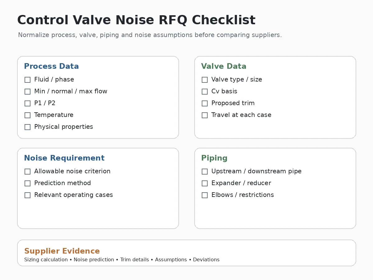
Supplier proposals are easier to compare when every bidder receives the same operating cases, piping assumptions and noise acceptance basis. The RFQ should identify the required calculation method, relevant cases, proposed trim, assumptions, technical deviations and any required documentation or acceptance evidence.
What Should a Supplier Provide for a Control Valve Noise Review?
A proposal that only states “low-noise trim included” does not provide enough engineering evidence for technical bid comparison. Each supplier should identify the calculation basis, operating cases, proposed trim, downstream assumptions and predicted result on the same RFQ basis.
| Supplier Deliverable | Buyer Review Point |
|---|---|
| Sizing calculation | Confirm the same minimum, normal and maximum operating cases are used. |
| Valve size and rated Cv | Check consistency with the documented sizing basis. |
| Predicted valve travel | Review controllability across the required operating range. |
| Noise prediction | Require a result for each relevant operating case, not one isolated value. |
| Prediction method | Confirm the method, applicable edition and stated assumptions. |
| Proposed trim | Require the supplier to identify which acoustic or hydraulic mechanism it addresses. |
| Outlet velocity | Confirm the downstream pipe condition and evaluation location used in the calculation. |
| Piping assumptions | Identify downstream diameter, pipe wall, expander and relevant geometry where required. |
| Cavitation / flashing assessment | Require this for applicable liquid-service cases. |
| الانحرافات الفنية | List differences from the datasheet, specification and RFQ explicitly. |
| وثائق المشروع | Confirm the required sizing sheet, noise calculation, drawings, datasheet revisions and agreed technical deviations before approval. |
Noise Calculation Basis for Supplier Comparison
A lower quoted dB(A) value is not automatically the better proposal if bidders used different engineering assumptions. For a meaningful technical comparison, hold the following basis consistent wherever applicable:
- same operating case and flow rate;
- same inlet and outlet pressure;
- same fluid properties and temperature;
- same downstream pipe basis;
- same control-valve sizing basis;
- same prediction method and applicable edition;
- same measurement, reference and acceptance conditions.
Common Control Valve Noise Selection Mistakes
- Using one arbitrary velocity limit. Velocity requires service-specific interpretation and a defined evaluation location.
- Checking only normal flow. Other cases may create more severe pressure ratios, valve openings or outlet conditions.
- Calling all liquid noise cavitation. Normal turbulent liquid flow can also generate hydrodynamic noise.
- Selecting low-noise trim without reviewing downstream piping. Valve-source treatment does not automatically solve transmission or structural-response issues.
- Treating acoustic insulation as a hydraulic solution. Transmission treatment does not remove the original hydraulic source.
- Selecting trim before completing valve sizing. Required Cv, travel, characteristic, shut-off duty and the full operating envelope must remain compatible with the proposed trim.
Practical Control Valve Noise Selection Workflow
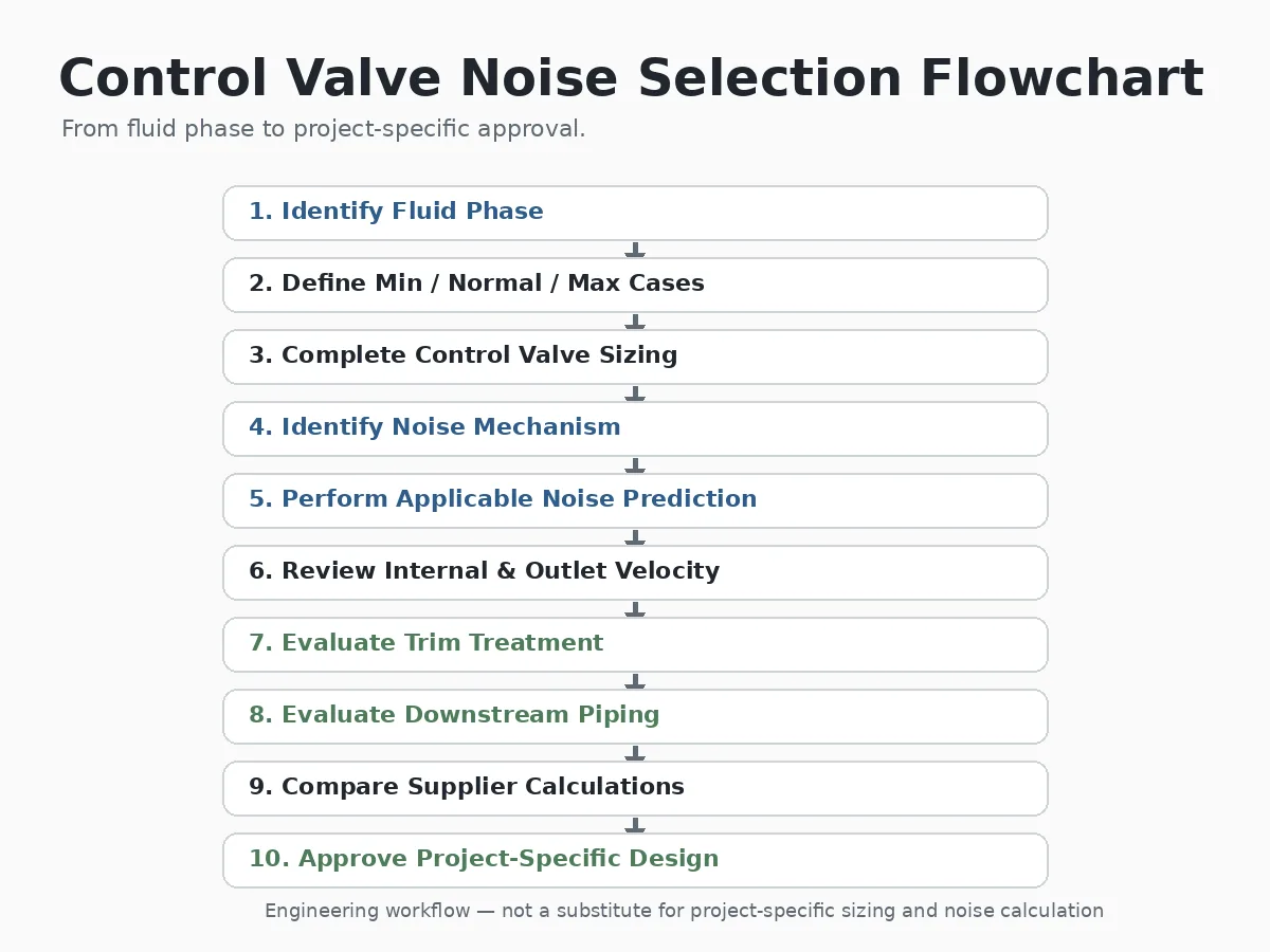
- Identify the fluid phase and relevant physical properties.
- Define minimum, normal, maximum and relevant transient cases.
- Complete the control-valve sizing review.
- Identify the dominant aerodynamic, hydrodynamic or mechanical mechanism.
- Perform the applicable valve-specific noise prediction.
- Review internal and downstream velocity on a defined basis.
- Evaluate trim-side source treatment.
- Evaluate downstream piping and transmission treatment.
- Compare supplier calculations on the same engineering basis.
- Approve the project-specific documented design.
Request Control Valve Noise & Sizing Review
Send the fluid composition and phase, minimum/normal/maximum flow, corresponding inlet and outlet pressures, temperature, valve and line size, upstream and downstream pipe size, project noise criterion, proposed or existing trim, required shut-off duty and the relevant piping arrangement.
For an existing noisy valve, also include actual valve travel, the operating condition when the noise occurs, photographs or layout information for nearby reducers and elbows, and any available inspection findings.
Submit Your Control Valve Dataأسئلة متكررة
What is the difference between aerodynamic and hydrodynamic control valve noise?
Aerodynamic noise is primarily associated with compressible gas or vapor flow. Hydrodynamic noise is generated by liquid flow and can result from normal turbulence as well as cavitation. Their prediction inputs and mitigation strategies are therefore different.
Does high control valve velocity always mean excessive noise?
No. Velocity is an important indicator, but it must be evaluated together with fluid phase, density, pressure conditions, valve geometry, the evaluation location, downstream piping and project acceptance criteria.
Can low-noise trim eliminate control valve noise?
Not necessarily. Trim may reduce noise at the valve source, but downstream velocity, piping geometry, acoustic transmission and structural response can remain important.
Is cavitation the only cause of hydrodynamic control valve noise?
No. Normal turbulent liquid flow can produce hydrodynamic noise without cavitation. Cavitation is one additional hydrodynamic noise mechanism that can increase noise, vibration and damage risk.
What data is required to predict control valve noise?
Typical inputs include fluid and phase, minimum/normal/maximum flow, inlet and outlet pressures, temperature, relevant fluid properties, valve and trim data, valve travel, downstream piping information and the project noise criterion.
Should control valve noise be calculated only at maximum flow?
No. Each relevant operating case should be reviewed separately because maximum flow, minimum flow or another operating case can govern for different reasons.
قيود هندسية: this article supports preliminary mechanism screening, control-valve noise review, RFQ preparation and supplier comparison. It does not establish final valve size, Cv, trim geometry, pressure-reduction stage count, universal velocity limits, guaranteed noise level, material suitability, cavitation severity, actuator size or service life.
Noise prediction is operating-case specific. A result calculated for one flow, pressure pair, downstream pipe size or valve travel should not automatically be applied to another operating condition. Pressure class is also not a fixed operating-pressure value; pressure-temperature suitability must be confirmed for the exact valve design, materials and applicable standard.
Final trim selection must remain compatible with required Cv, controllability, shut-off duty, fluid cleanliness, erosion or fouling risk and maintenance requirements. Final suitability depends on confirmed process data, project specifications, valve-specific coefficients, piping configuration and approved supplier calculations.
For available control-valve constructions and project-specific selection, review the صمامات تحكم category or submit the complete datasheet. Company scope and content responsibility are described on the Raymon Valve company information page.
 Arabic
  English
  German
  French
  Spanish
  Italian
  Portuguese
  Russian