
An L-port three-way ball valve usually connects one selected pair of ports at a time, making it a starting point for diversion or source selection. A T-port design can offer additional connections, including all three ports in certain configurations. Neither the port letter nor a 90°/180° travel angle guarantees a particular shutoff state. To specify the correct valve, compare the actual port-position drawing, permitted switching transitions, isolation and leakage requirements, and actuator position feedback—not just the nominal valve size or the L/T designation.
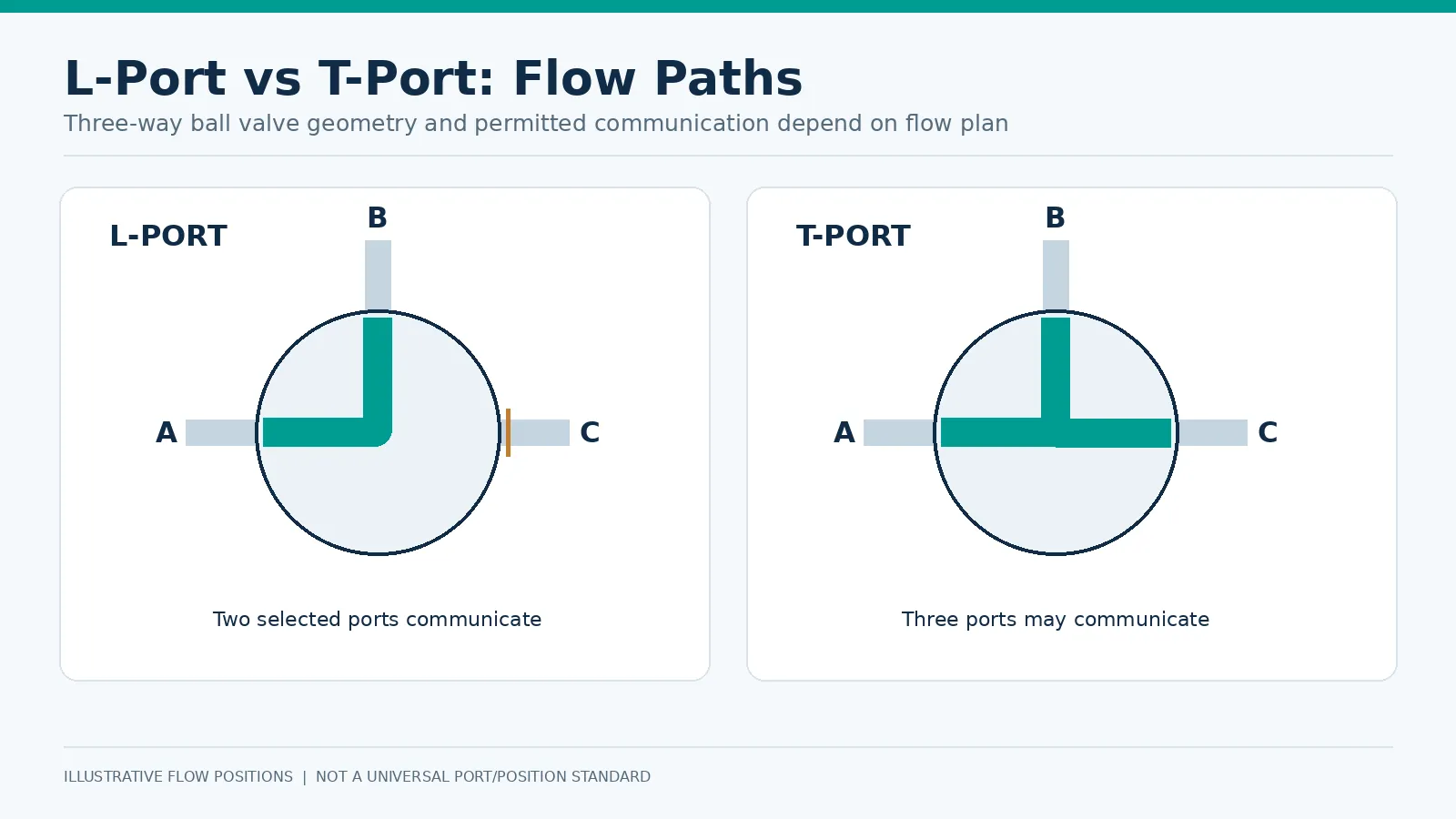
1. What Is the Difference Between L-Port and T-Port Three-Way Ball Valves?
Three-way ball valves have three external piping connections and an internal rotating passage. The L-shaped passage typically joins one selected pair of ports. A T-shaped passage can support different pairwise connections and, for some configurations, communication between all three. This geometric distinction is important but not sufficient to define all operational states.
L-Port Ball Valve: Two-Port Flow Routing
An L-port is often considered where a common line must be switched between two branches. It may select between two supplies or divert flow toward alternative destinations. Which port remains common depends on the manufacturer’s drilling, port orientation and permitted rotation. An all-off position must not be assumed.
T-Port Ball Valve: Multiple Flow Connections
A T-port arrangement can provide greater routing flexibility. It can be evaluated for combining streams or establishing multiple line connections. However, connection capability alone does not guarantee accurate proportional mixing, continuous circulation or a full shutoff position.
L-Port vs T-Port: Comparison at a Glance
| عامل الاختيار | L-port | T-port |
|---|---|---|
| Passage geometry | L-shaped passage | T-shaped passage |
| الاستخدام النموذجي | Selecting/diverting between two branches | Multiple connections, combining or diverting |
| All three ports connected | Not a conventional L-port function | Possible in certain flow plans |
| Complete shutoff | Not guaranteed; confirm configuration | Not guaranteed; confirm configuration |
| Actuator travel | Defined by approved flow plan | Defined by approved flow plan |
| Critical verification | Common port, off position, transient connections | Allowed pairs, all-port connections, off position |
2. How Do L-Port and T-Port Flow Paths Work?
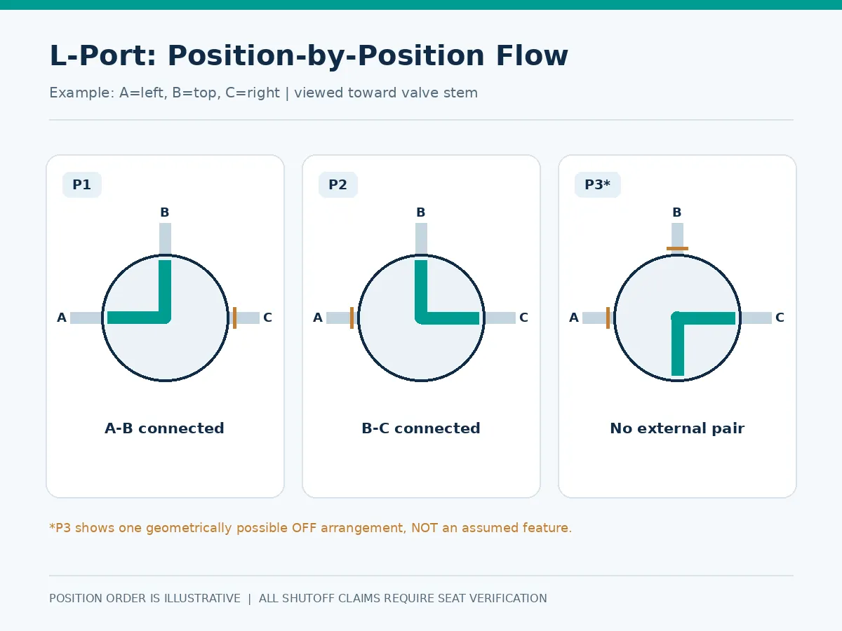
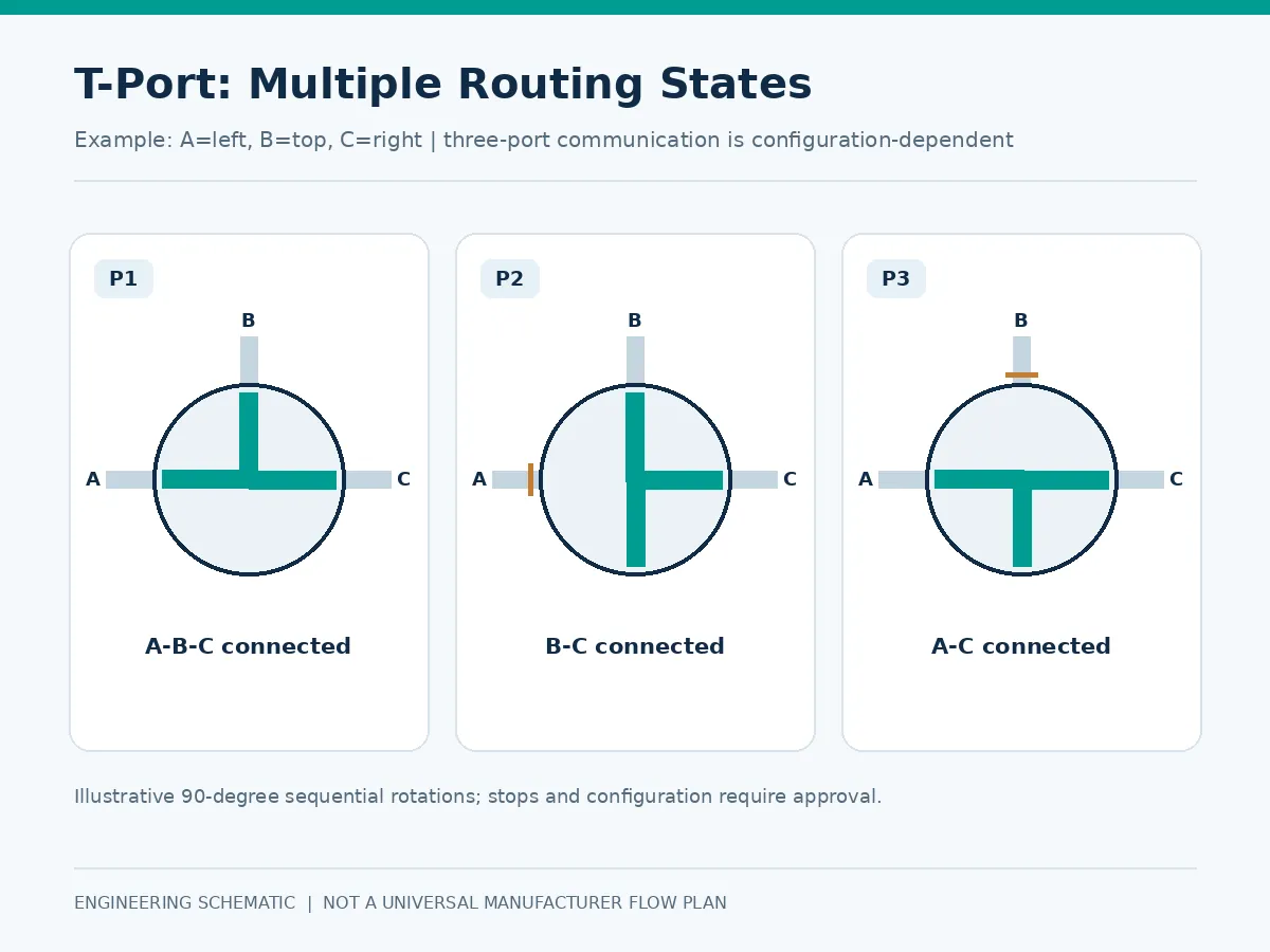
For the following illustrations, A is the left connection, B the top, and C the right when looking toward the stem. These labels are an editorial convention, not a universal manufacturer’s port numbering system. Rotation direction, stem-view reference and permissible stops must be stated on the approved drawing.
L-Port Flow Path Configurations
One illustrative flow plan uses P1 to connect A–B and P2 to connect B–C, making B the common port. Other L-port designs use different port combinations or stop arrangements. The supplier must confirm the actual routing schedule and whether a separate off state is available. In the illustration, P3* denotes no connection between any pair of external ports; it does not certify seat tightness, actuator stopping accuracy, or universal availability of an OFF position.
T-Port Flow Path Configurations
A T-port flow plan may allow two ports to connect in selected positions and all three to communicate in another. The precise sequence is not universal: one manufacturer’s 0° position cannot be assigned to another manufacturer’s valve without checking its drawing. The illustrated P1/P2/P3 sequence represents one conceptual T-bore rotation: three-port communication, B–C connection, then A–C connection, respectively; it is not a standard position schedule for all T-port valves.
Why Rotation Direction and Port Orientation Matter
A handle or actuator indicator alone does not prove which pipeline is connected. The valve’s stem orientation, defined viewing direction, travel direction and mechanical stops must match the process P&ID and controls narrative. Installation against an incorrect reference can reverse the intended switching sequence. Document whether angles are measured looking toward the stem from above, the actuator mounting side, or another agreed reference. Manual-handle orientation and actuator-coupling/indexing conventions must be independently verified; the handle arrow is not a universal control signal.
RFQ scenario — common-port ambiguity: A buyer specifies “L-port, 90°” for a duty requiring one supply to switch between two users, but does not identify the common port. Two quotations may offer different body orientations and still use the same product description. Prevent this mismatch by attaching a labeled A/B/C connection schedule and requiring the supplier to mark the exact operating positions on the approval drawing.
3. Three-Way Ball Valve Shutoff Matrix: Which Ports Are Open or Closed?
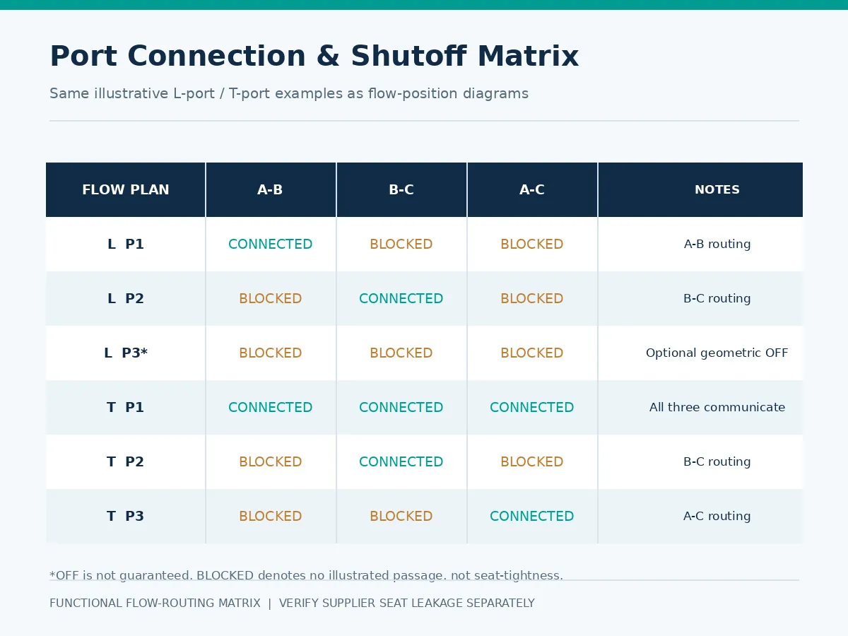
A connection matrix describes functional routing. It is not proof of seat tightness, pressure-direction sealing or complete process isolation.
Illustrative L-Port Connection Matrix
The following rows describe a hypothetical, specifically selected configuration, not all L-port designs:
| Illustrative position | A–B | B–C | A–C | الوظيفة المطلوبة |
|---|---|---|---|---|
| P1 | Connected | Not connected | Not connected | A ↔ B routing |
| P2 | Not connected | Connected | Not connected | B ↔ C routing |
| Off (only if provided) | Not connected | Not connected | Not connected | All paths functionally isolated; verify sealing |
T-Port Positions Require Model-Specific Confirmation
Instead of assigning unsupported universal open/closed states, the buyer should complete this template using the selected supplier’s flow plan:
| Position | A–B | B–C | A–C | Approval needed |
|---|---|---|---|---|
| P1 | Per approved drawing | Per approved drawing | Per approved drawing | نعم |
| P2 | Per approved drawing | Per approved drawing | Per approved drawing | نعم |
| P3 (if used) | Per approved drawing | Per approved drawing | Per approved drawing | نعم |
| All-off (if required) | Not connected | Not connected | Not connected | Must be demonstrated |
All-Ports-Closed vs Individual-Port Isolation
All-ports-closed refers to no intended internal communication among external connections in an approved state. Individual-port isolation refers to keeping a particular pressure source or branch separated under stated differential pressure and leakage requirements. A geometrically blocked path does not automatically meet a leakage acceptance criterion.
Why Flow Connection Does Not Guarantee Tight Shutoff
Sealing depends on seat arrangement, pressure direction, differential pressure, temperature, wear and the specified test scope. Where critical isolation is needed, the RFQ should identify every sealing boundary, the applicable test pressure/direction and acceptable leakage. An additional dedicated isolation valve may be required. A flow diagram establishes geometric communication; a blocked path establishes only nominal port separation; a witnessed or documented seat test establishes leakage acceptance under its stated test conditions. No one of these three is interchangeable with the others.
Acceptance distinction: “Not connected” in the table means there is no intended open passage between the named port pair in that position. It is not a measured leakage value, a pressure-direction seal qualification, or proof that one port is safely isolated from every pressure source. The purchase specification must identify the seat boundary, test direction, differential pressure, medium and acceptance limit when tight isolation matters.
4. Actuator Positioning: 90° vs 180° Rotation
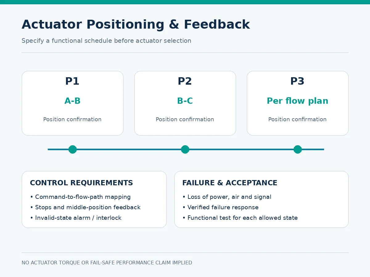
Actuation requirements depend on which discrete states the process needs. Two commanded states may be achieved with a suitable two-position actuator, while a three-position valve may need intermediate stops, appropriate control logic and separate position indication.
Two-Position and Three-Position Operation
The designation ‘three-way’ does not require exactly three operating positions. Specify the actual set of allowed states and the travel angle between them; do not assign universal P1/P2/P3 angles without supplier confirmation. For background on actuator motion and position indication, see valve actuator types and positioning principles.
| Control command | Required position | حالة التدفق | Required feedback |
|---|---|---|---|
| CMD-1 | P1 | A–B in illustrated L-port example | P1 reached |
| CMD-2 | P2 | B–C in illustrated L-port example | P2 reached |
| CMD-3 (optional) | P3 | Approved manufacturer flow plan | P3 reached |
| Signal or energy loss | Project-defined | Do not assume isolation | Alarm/verification as specified |
Actuator Stops, Feedback and Position Indication
A command signal confirms intent, not actual valve position. Define limit switches or position measurement for each required state. If an intermediate state is specified, verify it independently rather than relying only on end-stop indicators.
Intermediate Flow Paths During Switching
During travel the ball may briefly interrupt flow or permit an unintended pressure connection. For incompatible fluids, different-pressure supplies or equipment requiring continuous circulation, review the full transition sequence rather than merely the endpoint diagram.
Fail Position and Loss-of-Energy Behavior
Document the requested response to loss of air, electrical supply, control signal and emergency-shutdown command separately. ‘Fail safe’ is not a complete specification. Final actuator sizing requires model-specific torque data, maximum differential pressure, seat information, cycling duty and supply conditions; this article does not determine actuator torque or size.
For package interfaces and operating requirements, see Raymon Valve’s valve actuator package requirements. For the data needed to evaluate operating torque and actuator suitability, refer to the actuator selection and torque review.
Commissioning scenario — correct command, wrong branch: An actuator can indicate its end stop while the stem coupling or mounting orientation places the ball in the wrong flow configuration. This is a potential specification/commissioning failure, not a documented Raymon Valve case. Prevent it with an end-to-end functional test that records command, independent position indication and observed A/B/C path for every permitted state.
5. Mixing, Diverting and Bypass: Which Port Design Fits the Duty?
Diverting One Supply Between Two Lines
A common diverting duty sends one source toward either of two destinations. An L-port design is often a candidate when each approved position should connect only the common line and one selected branch. Review transitional cross-connections before acceptance.
Selecting Between Two Sources
In source selection, differing supply pressures and potential reverse flow may change the isolation requirements. A three-way ball valve should not be assumed to perform a check valve’s non-return function.
Combining or Distributing Flow
A T-port may be considered when simultaneous port communication is required. Flow proportion, however, is controlled by the hydraulic system and valve characteristics; an ordinary switching valve is not automatically a precise mixing-control valve.
Bypass and Recirculation Applications
Bypass duty requires confirmation of the minimum process flow, allowable interruption time and whether the intermediate flow paths are safe. Some applications will require separate regulating or protective elements.
Transition-State Acceptance: Break-Before-Make vs Make-Before-Break
A commanded endpoint can be correct while the movement between endpoints is unacceptable. In a critical switching duty, distinguish break-before-make (the outgoing connection is interrupted before the incoming connection is established) from make-before-break (temporary overlap may occur). These are required operating behaviors—not properties that can be inferred from the letters L or T. A design may also have partially open or throttled transitions, and whether those are acceptable must be assessed using process conditions and the model-specific ball/seat geometry. If transient cross-connection is prohibited, require the manufacturer to confirm the flow path throughout the specified rotation, not only the stationary endpoint diagrams.
| Process concern | Question for engineering review | الأدلة المطلوبة |
|---|---|---|
| Incompatible sources | Can two feeds communicate at any point during rotation? | Transition flow-path drawing or documented functional sequence |
| Continuous circulation | Is there a period when the required path is interrupted? | Transition design review and minimum-flow assessment |
| Pressure imbalance | Can pressure transfer to the inactive branch? | Differential-pressure cases and seat-sealing direction review |
| Safety-related state | What flow paths exist after each defined loss-of-energy event? | Cause-and-effect narrative and witnessed package test where specified |
Process scenario — switching between dissimilar sources: If one branch contains a flushing medium and another contains process fluid, a transient connection during ball rotation may be unacceptable even if both final valve positions are correct. The engineering review should establish whether the required sequence is break-before-make or make-before-break, whether either is physically achievable with the proposed drilling, and how the transition will be demonstrated. Do not infer the result from L-port/T-port naming alone.
6. Selection Matrix: When Should You Choose L-Port or T-Port?
| Application requirement | التوجيه الأولي | Essential check |
|---|---|---|
| Choose one of two branches | Often L-port | Confirm common port and seat configuration |
| Simultaneous three-port connection | T-port candidate | Confirm specific permitted operating position |
| Combine two inlet streams | T-port candidate | Review hydraulic performance, pressure and control duty |
| Full shutoff | Neither by default | Verify dedicated off state and leakage acceptance |
| Three commanded positions | Configuration-dependent | Check stop positions, feedback and transitional routing |
| Prevent cross-contamination | Engineering review | Check both steady and transient cross-connections |
A preliminary choice must still be checked against process medium, allowable pressure drop, pressure-temperature limits, materials, seat compatibility, differential pressure and intended actuation.
7. Engineering Risks and Common Specification Mistakes
| Risk | Potential outcome | التحقق |
|---|---|---|
| Wrong port map | Incorrect branch supplied | Approved piping-to-port mapping |
| Unintended flow while turning | Cross-connection or interrupted supply | Transition sequence and overlap evaluation |
| Unverified shutoff | Pressure migration | Seat design, test direction and acceptance criteria |
| Incorrect fail action | Unwanted diversion | Documented air/power/signal failure response |
| Insufficient capacity | Excessive pressure loss | Path-specific hydraulic data |
| Missing intermediate feedback | Unconfirmed commanded state | Factory functional and signal check |
One frequent purchasing mistake is to specify only ‘3-way T-port, DN size, pressure class’ while omitting the actual port map. This can result in an otherwise compliant-looking quotation that does not perform the required process function. Review pressure transfer, leakage from nominally blocked ports, and actuator failure response in the technical evaluation.
Minimum Acceptance Criteria for Each Isolated Port
When an application calls for a port to be isolated, the purchase specification should identify the pressure source, downstream boundary, direction and magnitude of differential pressure, seat leakage criterion, test method and required test position. This converts an ambiguous statement such as “Port C closed” into a verifiable requirement. A supplier’s standard shell pressure test is not evidence that every requested disconnected port pair meets the project’s seat leakage criterion.
Hydraulic screening scenario: A three-way valve matches the pipe nominal size and pressure class but provides different passage resistance along the two active paths. An equal-size replacement may therefore change branch flow or pump operating point. Ask for path-specific flow capacity or pressure-loss data at the specified positions; evaluate minimum, normal and maximum flow, fluid properties and available differential pressure before approving the package.
8. What Should Be Included in a Three-Way Ball Valve RFQ?
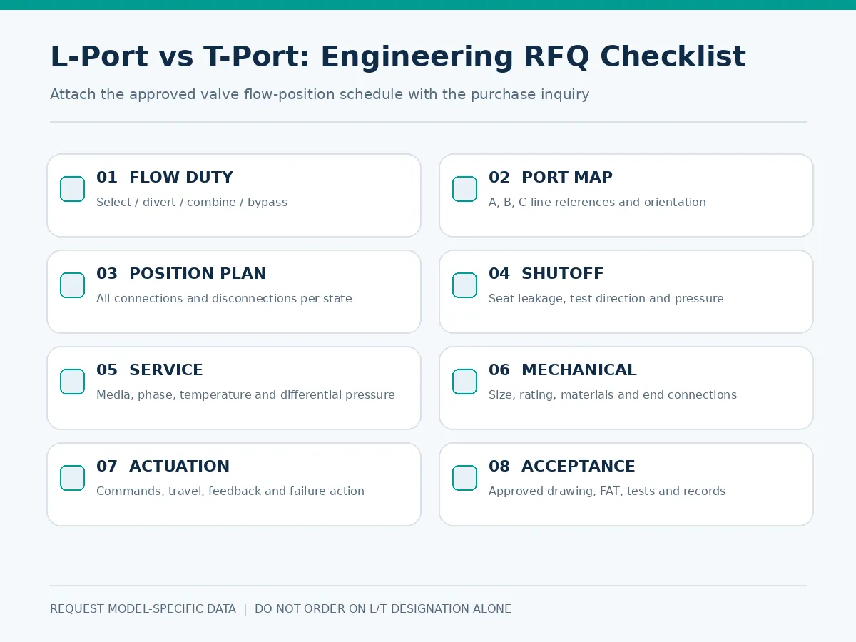
Provide a labeled piping sketch and a table of every permitted operating position. Request the supplier’s proposed flow plan as part of the technical offer, and require deviations to be stated clearly.
| RFQ field | Required project input |
|---|---|
| Duty and flow topology | Select, divert, combine, bypass; labeled A/B/C connections |
| Operating states | Permitted positions and port-to-port matrix |
| بيانات العملية | Media, phase, solids, flow, normal/design pressure and temperature |
| Mechanical | Size, rating/PN, end connections and applicable specifications |
| المواد والختم | Body/ball/stem/seat/packing; allowable leakage per seat boundary |
| التشغيل | Manual/pneumatic/electric; position schedule, operating time and fail response |
| أنظمة التحكم | Command inputs, intermediate positioning, feedback and alarms |
| التحقق | Flow drawing, shell/seat/functional test scope and documentation |
Required Flow-Position Schedule
Identify A, B and C on the plant drawing and map them to the actual valve connections. For each position, mark every allowed and prohibited pair; also state any unacceptable connections during rotation.
Actuation, Inspection and Documentation
Specify manual/pneumatic/electric operation, command method, travel, intermediate stops, position feedback, failure response, functional acceptance and required documentation. Shell testing, seat leakage testing and position-by-position functional verification are separate activities, each with its own acceptance scope.
Technical Bid Normalization: Compare Like-for-Like Packages
Two offers labeled “3-way T-port ball valve” may propose different available valve positions, seat designs or actuator accessories. Before comparing commercial prices, require each supplier to identify deviations against the same approved position schedule and testing requirements.
| Bid comparison item | استجابة المورد المطلوبة | Buyer review |
|---|---|---|
| Ball drilling and port layout | Marked drawing and flow-pattern code | Matches P&ID A/B/C connections? |
| Required stationary positions | Connected/disconnected pairs at every stop | All commanded states available? |
| Travel transition | Sequence and any temporary flow overlap | Prohibited cross-connections avoided? |
| Shutoff boundaries | Seat arrangement, pressure directions and test scope | Leakage acceptance supported? |
| حزمة مشغلة | Torque basis, travel, controls, feedback and failure behavior | Complete assembly compliant with functional narrative? |
| الانحرافات الفنية | Explicit exceptions and alternatives | Resolve before purchase order |
Pre-PO decision gate: Reject an unqualified “standard L-port/T-port” response if the vendor has not identified its flow-pattern code, ball/seat arrangement, operating stops and position-by-position connection schedule. For actuated packages, also request torque data at the governing differential pressure, travel time, fail response and matching position-feedback logic. Compare deviations in a single technical bid tabulation.
9. Supplier Verification: Drawings, Testing and Acceptance
Approved Flow Diagram and General Arrangement
The approval package should show port labeling, ball passage, mounting reference, direction of travel and every permitted operating stop. Record the drawing number and revision, the physical line-to-port mapping, the viewing direction, actuator coupling orientation and each command-to-position correspondence. Model-specific approved drawings govern over generic flow-pattern illustrations.
Position-by-Position Functional Verification
At factory acceptance, check the command, achieved mechanical position, actual port connections and indicated feedback for each specified state. Test the intermediate position independently where applicable. Where specified, retain a signed position-by-position acceptance record including target command, measured mechanical position, connected and isolated ports, indicated status, supply-failure response and any agreed transition-state evidence. A stationary P1/P2/P3 check does not by itself verify the complete transition path.
Seat Leakage and Pressure Test Scope
Verify the required sealing boundaries under agreed pressure directions and criteria. A position test does not replace shell or seat leakage testing. Applicable test standards, editions and acceptance levels must be defined by the actual project specification and selected product.
Actuator and Limit-Switch Verification
Confirm actuator travel, mechanical limits, switch/positioner operation, alarm signals and specified loss-of-energy responses on the supplied assembled package.
Acceptance Record: Evidence to Retain with the Purchase Order
For procurement traceability, retain the approved port-position drawing, the signed technical deviation list, agreed seat/leakage test criteria, actuator position and feedback test records, and the as-supplied tag/connection mapping. Where witness testing is specified, record actual acceptance results rather than relying on a generic catalogue diagram. The scope should be proportionate to the process risks and project requirements.
10. Final Selection Recommendations
An L-port valve is generally a sensible starting point for choosing between two flow branches. A T-port becomes relevant when additional connections or simultaneous three-port communication are required. Neither type should be ordered solely on its port designation. Final approval requires an accepted flow-position map, isolation criteria, safe transition behavior, appropriate actuation and supplier verification.
Explore related industrial ball valve configurations and further engineering resources. For supplier context, see عن Raymon Valve.
أسئلة متكررة
What is the main difference between an L-port and a T-port three-way ball valve?
An L-port typically connects a selected pair of ports, while a T-port can offer additional connections, including three-port communication in some configurations. The manufacturer’s flow plan determines the available positions.
Can a T-port three-way ball valve completely shut off all three ports?
Not by default. Many T-port valves are intended for flow routing without a full-off position. Request an approved all-off configuration and leakage verification if full isolation is required.
Does an L-port three-way ball valve always have a closed position?
No. Certain configurations offer an intermediate off position, but many function only as two-path selectors. Confirm the supplied valve’s actual position diagram.
Can a three-way ball valve use a 90-degree actuator?
Yes, if the required positions are compatible with that actuator travel and stop arrangement. Other designs may require 180-degree travel or a validated intermediate-position control scheme.
Which port design is better for mixing and diverting applications?
An L-port is often considered for choosing between two paths. A T-port can be suitable where multiple ports need to communicate. Proportional mixing requires additional hydraulic and control review.
What information is required when ordering an actuated three-way ball valve?
Provide the labeled port diagram, each permitted flow position, process conditions, shutoff criteria, materials, actuator travel, control and feedback requirements, failure response, and test/documentation scope.
Request Three-Way Ball Valve Selection Review
Submit your required port connections, position schedule, medium, flow, pressure, temperature, valve size/rating, shutoff requirements, material preferences, actuator type, feedback and failure-response requirements for a project-specific quotation discussion.
Submit Your Valve Datasheet / RFQملاحظة هندسية: Flow and position examples are illustrative, not a substitute for a manufacturer’s model-specific approved drawings, pressure/temperature ratings, material review, functional testing or responsible-engineer approval. Image URLs were confirmed accessible by the site owner; no independent automated HTTP/media verification is asserted here.
 Arabic
  English
  German
  French
  Spanish
  Italian
  Portuguese
  Russian