Definieren Sie die Anwendungsgrenzen für das ZMAS Hochdruck-Winkelregelventil
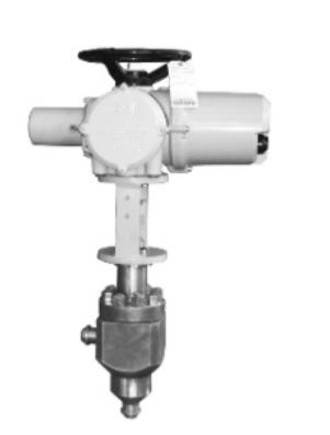
Ein ZMAS Hochdruck-Winkelregelventil wird für die modulierende Prozessregelung bewertet. Ein Drosselorgan ändert den effektiven Strömungsquerschnitt als Reaktion auf ein Steuersignal. Die installierte Kennlinie, Cv, Druckrückgewinnung, Drosselgeschwindigkeiten und Stellungsreglerauflösung bestimmen die Regelgüte.
Verwenden Sie den Namen als Ausgangspunkt. Die technische Freigabe hängt weiterhin vom 90-Grad-Strömungsweg des Gehäuses, den Rohrleitungsbelastungen und der Erosions- oder Kavitationsbelastung, dem vollständigen Betriebsbereich, den installierten Schnittstellen und der messbaren Abnahme ab.
Winkel
90-Grad-Strömungsweg, Rohrleitungsbelastungen und Erosions- oder Kavitationsbelastung. Definieren Sie Strömungsrichtung, Druckabfall, Phase, Geschwindigkeit, Rohrleitungsbelastungen, Entwässerung und Wartungszugang.
Anwendungsbereich
Bestätigen Sie jeden Druck-, Temperatur-, Differenzdruck- und Schaltfall für dieses ZMAS Hochdruck-Winkelregelventil.
Installierte Schnittstelle
Überprüfen Sie Enden, Bohrung, Flussrichtung, Ausrichtung, Bedienereingriffsbereich, Lasten und Wartungszugang.
Bestellspezifische Abgrenzung
Betrachten Sie diese Seite als technischen Leitfaden und überprüfen Sie anschließend die tatsächliche Konfiguration, Grenzen und Nachweise in kontrollierten Projektdokumenten.
Veröffentlichte Konfigurationsdaten für das ZMAS Hochdruck-Winkelregelventil – Bestätigung erforderlich
Die unten aufgeführten Werte sind aus der vorherigen öffentlichen Produktlistung übernommen, damit nützliche Modellinformationen während des Qualitäts-Rebuilds nicht verloren gehen. Sie stellen keinen universell verfügbaren Bereich, kein Zertifikat und keine Bestellverpflichtung dar. Bestätigen Sie jeden Wert in dem akzeptierten Angebot, dem Tag-Datenblatt und der genehmigten Zeichnung.
| Parameter | Vorherige Listung | Erforderliche Bestellprüfung |
|---|---|---|
| Produkttyp | Nicht in der vorherigen öffentlichen Liste angegeben. | Bestätigen Sie das genaue Modell, die Konstruktion und die gelieferte Konfiguration. |
| Nennweite / DN | Nicht in der vorherigen öffentlichen Liste angegeben. | Bestätigen Sie jede bestellte Kennzeichnung und die verfügbare Innengarnitur- oder Bohrungskombination. |
| Druckstufe | Nicht in der vorherigen öffentlichen Liste angegeben. | Bestätigen Sie den maßgeblichen Standard, die Klasse und die Temperaturbasis. |
| Temperatur | Nicht in der vorherigen öffentlichen Liste angegeben. | Bestätigen Sie die Konstruktions-, Betriebs-, Anfahr- und Störfall-Metalltemperaturen. |
| Anschlussart | Nicht in der vorherigen öffentlichen Liste angegeben. | Bestätigen Sie Standard, Flanschtyp, Schedule, Bohrung und Schnittstelle. |
| Strömungskoeffizient / Kennlinie | Nicht in der vorherigen öffentlichen Liste angegeben. | Berechnete Fälle, Innengarnitur, Hub und Verhalten im eingebauten Zustand bestätigen. |
| Gehäuse- / Haubenwerkstoff | Nicht in der vorherigen öffentlichen Liste angegeben. | Güte, Produktform, Wärmebehandlung und Aufzeichnungen der Komponenten bestätigen. |
| Innengarnitur- / Schließmaterial | Nicht in der vorherigen öffentlichen Liste angegeben. | Alle medienberührten Komponenten, Härte, Beschichtung und Paarung bestätigen. |
| Sitz- / Dichtungsmaterial | Nicht in der vorherigen öffentlichen Liste angegeben. | Kompatibilität, Kriterium für Leckage und Druck-Temperatur-Grenze bestätigen. |
| Betätigung / Antrieb | Nicht in der vorherigen öffentlichen Liste angegeben. | Worst-Case-Last, Ausfallzustand, Medien, Geschwindigkeit und Zubehör bestätigen. |
| Leckagebasis | Nicht in der vorherigen öffentlichen Liste angegeben. | Standard, Ausgabe, Prüfrichtung, Medium und messbare Akzeptanz bestätigen. |
Nachweisgrenze: wo die vorherige Auflistung unvollständig oder umständlich übersetzt war, rät diese Seite keinen Wert. Raymon Valve sollte vorläufige Webdaten durch das kontrollierte Produktdatenblatt ersetzen, sobald es verfügbar ist.
Erstellen Sie die technischen Anforderungen, bevor Sie das Modell genehmigen
Die Tabelle wandelt Eingaben zur Anwendung für das ZMAS Hochdruck-Winkelregelventil in Prüfpunkte und mit Tags verknüpfte Nachweise um.
| Prüfbereich | Technische Fragestellung | Erforderlicher Datensatz |
|---|---|---|
| Auslegungsfälle | Mindest-, Normal-, Maximal-, Anfahr- und Störfallfälle erfordern verifizierte Fluideigenschaften und Drücke. | Frieren Sie den akzeptierten Wert im Tag-Datenblatt ein und verifizieren Sie ihn auf der genehmigten Zeichnung. |
| Drosselgarnitur-Anforderungen | Kavitation, Verdampfung, choked gas flow, Lärm, Erosion und Regelbereich müssen bewertet werden. | Erfassen Sie die Auswahlgrundlage, etwaige genehmigte Abweichungen und den für die Abnahme verwendeten Datensatz. |
| Antrieb | Erforderlicher Schub oder Drehmoment, Ansprechverhalten bei Ausfall, Hubgeschwindigkeit und Versorgungsmedien müssen aufeinander abgestimmt sein. | Offenen Punkt vor Freigabe klären und tagbezogene Nachweise im Abschlussdossier aufbewahren. |
| Zubehör | Stellungsregler, Magnetventile, Endschalter, Luftaufbereitung und Anforderungen für explosionsgefährdete Bereiche bilden eine Einheit. | Machen Sie diese Anforderung durch das Bestelldatenblatt, die Konstruktionsprüfung und den Inspektionsplan nachprüfbar. |
| Winkel | Fließrichtung, Druckverlust, Phase, Geschwindigkeit, Rohrleitungsbelastungen, Entwässerung und Wartungszugang definieren. | Benennen Sie das steuernde Dokument, den verantwortlichen Prüfer und den Inspektions- oder Berechnungsdatensatz. |
Ein Standardtitel allein ist keine Akzeptanz. Ordnen Sie seinen Geltungsbereich, seine Ausgabe und die erforderlichen Nachweise dem Ventiletikett zu.
Wo diese Konfiguration passen könnte – und was sie zum Versagen bringen kann
Dimensionieren Sie ein Regelventil nicht nur nach dem Rohrdurchmesser; ein falscher Cv-Wert kann zu schlechter Auflösung, Geräuschen, Kavitation oder vorzeitigem Verschleiß der Innengarnitur führen. Die endgültige Entscheidung muss Systeminteraktionen, Belastungen am Lebensende, Degradation und wie ein Ausfall erkannt oder eingedämmt wird, abdecken.
Definieren Sie die Fertigungs- und Prüfnachweise vor der Freigabe
Die Nachweise sollten die gelieferte Konfiguration, Revision, Charge oder Losnummer und das anzuwendende Prüfverfahren identifizieren. Verwenden Sie die Leitfaden für Armaturenstandards zur Trennung von Produkt-, Druckstufen-, Maß-, Anschluss- und Prüfumfang.
Auslegungsbasis
Kontrollierte Konfiguration, Schnittstellenzeichnung, Berechnungen und abgeschlossene technische Klärungen.
Materialidentität
Komponenten-Zertifikate, Wärme- oder Chargenrückverfolgbarkeit, Wärmebehandlung, Härte und erforderliche PMI oder NDE.
Prüfung und Tests
Genehmigter ITP, Verfahren, kalibrierte Instrumente, Ergebnisse, Zeugenprotokolle und NCR-Abschluss.
Die Gehäusekrümmung kann Geschwindigkeit und Erosion konzentrieren; die Geometrie muss zum Prozessfall passen.
Keine Aussage hier stellt eine uneingeschränkte Zertifizierung dar; Normen, Ausgaben und Nachweise unterliegen weiterhin der Projektprüfung.
Informationen für ein technisches Angebot auf Tag-Ebene
Eine nützliche RFQ kombiniert Prozessdaten, Rohrleitungsstandard, Konstruktion und Werkstoffe, Anforderungen an den Antrieb/Aktor, Abnahmekriterien und Lieferdokumente.
Heben Sie für ein ZMAS Hochdruck-Winkelregelventil auch den 90-Grad-Strömungsweg des Gehäuses, Rohrleitungsbelastungen und Erosions- oder Kavitationsbelastung hervor. Listen Sie ungelöste Annahmen als Abweichungen auf, anstatt sie stillschweigend in das Angebot einzubetten.
Technische Überprüfung auf Tag-Ebene anfordern
Geben Sie die tatsächliche Anwendung an; die Antwort trennt bestätigte Anforderungen von Annahmen und identifiziert die noch erforderlichen Prüfungen.
Folgen Sie dem Produkt-, Anwendungs- und Inspektionsweg
Produktfamilie
Vergleichen Sie die Hauptkonstruktionen und Auswahlgrenzen dieser Ventilfamilie.
Projektventilauslegung
Risiken durch Druck, Temperatur, Korrosion, Verschleiß oder Projektanforderungen bewerten.
Prüfung und Inspektion
Druckprüfumfang, Abnahmekriterien, Instrumentierung, Zeugenpunkte und Dokumentation festlegen.
Wandeln Sie das ZMAS Hochdruck-Winkelregelventil von einer allgemeinen Anfrage in eine prüfbare technische Entscheidung um
Dieser Abschnitt befasst sich mit der Entscheidung, die ein Besucher wahrscheinlich treffen möchte – nicht nur mit der Bedeutung des Seitentitels. Verwenden Sie ihn, um erforderliche Eingaben zu identifizieren, den Vorschlag zu vergleichen und den Datensatz anzugeben, der die Annahme beweist.
| Entscheidung | Was zu tun ist | Zu speichernde Nachweise |
|---|---|---|
| Problemstellung | Definieren Sie für das ZMAS Hochdruck-Winkelregelventil das erforderliche Systemergebnis, die Ausfallkonsequenz und die messbare Abnahme, bevor Sie die Hardware auswählen. | Funktionale Anforderung |
| Machbare Optionen | Vergleichen Sie mindestens die praktischen Konstruktions-, Material-, Dichtungs- und Betätigungsalternativen, einschließlich der Gründe für die Ablehnung. | Optionen- und Kompromissmatrix |
| Randbedingungen | Prüfen Sie jeden normalen, transienten, Anfahr-, Abfahr-, Wartungs- und Stromausfallfall, der die Lösung ändern kann. | Genehmigte Anwendungsdaten |
| Validierung | Verknüpfen Sie jeden beanspruchten Vorteil mit einer Berechnung, Zeichnung, Qualifizierung, Inspektion oder einem Pakettest, der für die Bestellung gilt. | Verifizierungs- und Nachweisplan |
Wie dieser Leitfaden für ZMAS Hochdruck-Winkelregelventile verwendet werden sollte
Diese Seite behauptet nicht, dass eine genannte Person, ein Zertifikat, eine Qualifikation, ein installiertes Projekt oder ein Leistungsergebnis für eine zukünftige Bestellung gilt. Die Produktkonformität wird erst bestätigt, wenn das akzeptierte Angebot, die genehmigte Zeichnung, die Verfahren und die endgültigen Fertigungs-/Prüfprotokolle die gelieferte Konfiguration identifizieren.
Technische Anforderungen und Standards können sich ändern. Überprüfen Sie die offizielle Quelle, die Vertragsausgabe, die Projektvorrangigkeit und die Käuferoptionen. Siehe unsere Richtlinie zur Überprüfung technischer Inhalte und Nachweise, Unternehmensinformationen, Inspektionsansatz oder Korrektur oder Anwendungsfrage einreichen.
Fragen zum ZMAS Hochdruck-Winkelregelventil
Welche Informationen werden zur Auswahl eines ZMAS Hochdruck-Regelventils mit Schrägsitz benötigt?
Geben Sie das Medium und seine Zusammensetzung, alle Druck- und Temperaturbereiche, die Nennweite, den Durchfluss oder die Differenzdruck (falls relevant), die erforderliche Funktion, die Anschlussart, die Werkstoffe, das Absperrkriterium, die Betätigung, die Normen, die Prüfung und die Dokumentation an. Für diese Konfiguration muss die Überprüfung speziell den 90-Grad-Strömungsweg, Rohrleitungsbelastungen sowie Erosions- oder Kavitationsbelastung berücksichtigen.
Welche Normen gelten für ein ZMAS Hochdruck-Regel-Winkelventil?
Die Antwort hängt von der Produktkonstruktion, der Projektgerichtsbarkeit und der Spezifikation des Käufers ab. Ein Produktstandard kann den Konstruktionsumfang abdecken, während separate Standards Druck-Temperatur-Bewertungen, Abmessungen, Anschlüsse, Druckprüfungen, Brandschutz, Emissionen oder Materialien regeln. Die Körperdrehung kann Geschwindigkeit und Erosion konzentrieren; die Geometrie muss dem Prozessfall entsprechen.
Wie sollte die Druck- und Dichtheitsprüfung des ZMAS Hochdruck-Winkelregelventils spezifiziert werden?
Definieren Sie die Prüfkonfiguration und die messbaren Akzeptanzkriterien anstelle einer generischen Werksprüfung. Beziehen Sie kalibrierte Instrumente, Ventilposition, Druckrichtung und tag-bezogene Ergebnisse mit ein.
Kann ein ZMAS Hochdruck-Regel-Winkelventil mit einem Antrieb geliefert werden?
Automatisierung erfordert mehr als nur die Anpassung eines Montageflansches. Überprüfen Sie die maximale Last über den gesamten Hub, den minimalen Vorrat, die Kupplungs-/Spindelkapazität, Anschläge, Steuerungen und die erforderliche Ausfallreaktion.
Wann sollte ein ZMAS Hochdruck-Regel-Schrägsitzventil nicht ausgewählt werden?
Wählen Sie es nicht aus, wenn seine qualifizierte Konstruktion die Anforderungen an Prozess, Absperrung, Werkstoffe, Dynamik, Wartung oder Dokumentation nicht erfüllt. Dimensionieren Sie ein Regelventil nicht nur nach dem Rohrdurchmesser; ein falscher Cv-Wert kann zu schlechter Auflösung, Geräuschen, Kavitation oder vorzeitigem Verschleiß der Innengarnitur führen. Die Alternative sollte erst nach einem Vergleich der vollständigen Betriebsbedingungen gewählt werden.