
Industrial valve applications depend on the process duty, not the industry name alone. Oil and gas, chemical, power, water and mining systems use different valve constructions for isolation, regulation, non-return and pressure management. To shortlist a suitable type, engineers must check the medium, operating and design pressure and temperature, flow conditions, material compatibility, sealing requirements and failure consequences before preparing the valve datasheet or RFQ.
This guide explains industrial valve applications by industry and connects typical process duties with ten commonly specified valve categories. It is intended for EPC contractors, process and piping engineers, plant operators and procurement teams preparing an initial selection review or RFQ. It does not replace project-specific sizing, engineering calculations or approved specifications.

Applications de vannes industrielles par secteur
Industrial sectors do not use one universal valve arrangement. The process medium, operating envelope, required function and consequences of failure determine which valve constructions should be evaluated. The examples below are preliminary application routes, not blanket recommendations for every plant or service.
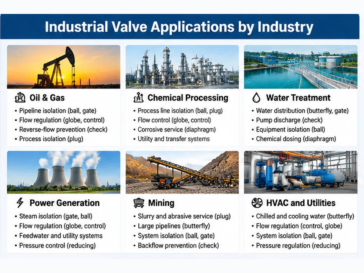
| Industrie | Typical process duties | Valve types to evaluate | Key engineering checks |
|---|---|---|---|
| Pétrole et gaz | Pipeline isolation, production flow, separation, compression and utility services | Ball, gate, check, plug, control and pressure-protection devices | Fluid composition, pressure/temperature envelope, leakage, fire-safe/emission requirements where specified, and transient conditions |
| Petrochemical and chemical processing | Feed, transfer, reactor, storage, dosing and utility lines | Ball, globe, plug, diaphragm, control and relief devices | Composition/concentration, corrosion, solids, phase, temperature and sealing compatibility |
| Power generation | Steam, feedwater, cooling water, condensate and auxiliary systems | Gate, globe, check, control, butterfly and pressure-reducing valves | Steam conditions, thermal cycling, pressure drop, transient behavior and applicable equipment requirements |
| Water and wastewater | Transmission, pumping, treatment, filtration, dosing and distribution | Butterfly, gate, check, ball and diaphragm valves | Water quality, suspended solids, corrosion, flow, pressure and maintenance access |
| Mining and mineral processing | Slurry transfer, tailings, dilution water, reagent dosing and dewatering | Specialized slurry/plug/pinch designs, plus suitable check and isolation valves | Solids loading, particle size, abrasiveness, blockage, erosion and maintainability |
| HVAC and industrial utilities | Chilled water, cooling water, compressed air and building/plant utilities | Butterfly, ball, globe, check and pressure-reducing valves | Flow range, pressure loss, control duty, installation space and actuator requirements |
These industry examples identify candidates for further review. They do not establish that a particular valve material, pressure class, temperature range or design is suitable without the actual process data and project requirements.
For project screening, add the consequence of an incorrect selection to the application review. A valve that is mechanically installable may still be unsuitable for the required duty.
| Review point | What to establish | Potential consequence if missed | Preuves à demander ou à vérifier |
|---|---|---|---|
| Service d'isolement | Required shut-off direction, frequency, differential pressure and allowable leakage | Passing leakage, seat damage or inability to isolate equipment as intended | Valve datasheet, seat design, specified closure test and acceptance criteria |
| Regulating duty | Minimum/normal/maximum flow, inlet/outlet pressure, temperature and control objective | Unstable control, excessive pressure drop, noise, cavitation or erosion | Process cases, sizing calculation, trim data and actuator basis |
| Non-return duty | Flow profile, reverse pressure, installation orientation and closing dynamics | Chatter, slam or damaging system transients | System transient assessment where warranted, check-valve design data and installation instructions |
| Pressure management | Set/operating conditions, downstream design pressure and credible failure cases | Inadequate pressure control or incomplete overpressure protection | Relief/pressure-control design basis and project protection review |
1. Ball Valve Applications
Ball valves use a rotating ball with a through-port to open or close a flow path. Quarter-turn operation makes them common candidates for pipeline and equipment isolation.
Typical applications
- Oil and gas pipelines: isolation in upstream, midstream and downstream systems, subject to the required valve design and project specification.
- Chemical processing: isolation of process lines, storage systems and transfer equipment after checking wetted-material compatibility.
- Fuel and gas distribution: shut-off duties where seat sealing, stem sealing and applicable leakage requirements are defined.
- Water and utilities: equipment isolation and utility pipelines where compact construction and quick operation are useful.
Selection checks
- Floating or trunnion-mounted construction; full or reduced port.
- Soft or metal seat and the required shut-off criteria.
- Body, ball, stem, seat and packing material compatibility.
- Pressure-temperature rating, differential pressure and operating torque.
- Manual or automated operation, including required fail position where applicable.
Application boundary: Standard on/off ball valves should not automatically be treated as control valves. Some purpose-designed or characterized ball-valve constructions can modulate flow, but suitability depends on sizing, flow characteristic, velocity, pressure drop and seat/trim design. Confirm the specific design and service cases before using one for throttling.
2. Gate Valve Applications
Gate valves use a movable gate or wedge to open or close the flow passage. They are commonly considered for isolation where low flow resistance in the fully open position is desirable.
Typical applications
- Water transmission: municipal and industrial water pipelines, distribution networks and large isolation points.
- Oil and gas transportation: selected process and pipeline isolation duties.
- Power generation: steam, water and utility systems, with construction selected for the actual pressure and temperature.
- Industrial process piping: isolation where the medium and operating conditions are compatible with the proposed design.
Selection checks
- Wedge construction, stem arrangement and bonnet design.
- Pressure-temperature rating and body/trim materials.
- End connection, face-to-face dimensions and installation clearance.
- Operating torque, operation frequency and maintenance access.
- Required inspection, testing and documentation.
Application boundary: Gate valves are generally intended for fully open or fully closed operation. Partially open continuous throttling can contribute to vibration, erosion and internal damage.
3. Globe Valve Applications
Globe valves regulate flow through a movable disc and seat arrangement. They can provide controlled adjustment, usually with a higher pressure drop than a comparable full-bore isolation valve.
Typical applications
- Steam systems: selected flow regulation and isolation duties with temperature, pressure drop and thermal cycling considered.
- Cooling water: manual flow adjustment where the system can accommodate the pressure loss.
- Chemical processing: process flow adjustment when trim and sealing materials suit the medium.
- Power generation: selected auxiliary and process lines requiring regulation or isolation.
Selection checks
- Required flow characteristic and allowable pressure drop.
- Medium, temperature, pressure and potential erosion/corrosion.
- Disc, seat and body material; leakage requirement.
- Manual or actuated operation and operating frequency.
Application boundary: A manual globe valve should not automatically replace a dedicated control valve where automatic process control, dynamic response or a defined control characteristic is required.
4. Butterfly Valve Applications
Butterfly valves use a rotating disc in the pipeline. Their compact construction and relatively low weight can be advantageous for large-diameter piping and utility systems.
Typical applications
- Water treatment: distribution, filtration, pumping stations and treatment plant pipelines.
- HVAC and cooling: chilled-water circulation and cooling-water networks.
- Large-diameter pipelines: applications where weight, installation space and operating arrangement matter.
- Power and utilities: selected cooling-water and auxiliary-water duties.
- Chemical processing: selected services where disc, liner, seat and body materials are compatible.
Selection checks
- Concentric, double-offset or triple-offset design.
- Resilient or metal seat; required leakage performance.
- Disc, shaft, seat and body material compatibility.
- Pressure-temperature limits, flow velocity and shut-off differential pressure.
- Actuator torque, installation orientation and clearance.
Application boundary: Butterfly valves include concentric and offset designs with different sealing and operating characteristics. Some high-performance or eccentric designs may be suitable for selected modulating duties; a conventional resilient-seated design should not be assumed suitable for every high-temperature, high-pressure or severe-service condition. Verify the exact construction and rating.
5. Check Valve Applications
Check valves permit flow in the intended direction and restrict reverse flow. They generally operate automatically through differential pressure and fluid forces rather than a manual actuator.
Typical applications
- Pump discharge: reduce reverse flow when a pump stops.
- Water networks: restrict unwanted reverse flow in distribution systems.
- Compressor systems: protect selected discharge arrangements against reverse flow.
- Oil and gas/process pipelines: maintain intended flow direction where required by the process design.
Common designs and selection checks
Common designs include swing, dual-plate, lift and axial/nozzle check valves. Review minimum and normal flow, reverse pressure, closing behavior, installation orientation, solids content and pressure loss. Where rapid flow changes or damaging reverse velocity are credible, assess the system transient behavior rather than selecting from nominal pipe size alone.
Application boundary: Check valve selection is a dynamic system question, not only a nominal size and pressure-class choice. A poorly matched closing characteristic may contribute to pressure surges. A check valve should not be treated as a positive isolation device.
6. Control Valve Applications
Control valves automatically vary flow resistance to regulate a process variable and are commonly integrated with instrumentation and a control loop.
Typical applications
- Flow control: regulate liquid or gas flow in chemical and process plants.
- Pressure control: maintain upstream or downstream pressure according to the control arrangement.
- Temperature control: adjust heating or cooling medium flow.
- Power and oil/gas processing: regulate selected steam, feedwater, production and process duties.
Selection checks
- Minimum, normal and maximum flow; inlet and outlet pressures.
- Fluid phase, density, vapor pressure and operating temperature.
- Allowable pressure drop and required flow characteristic.
- Cavitation, flashing, noise, vibration and outlet velocity risks.
- Actuator sizing inputs, supply conditions, control signal and fail position.
Application boundary: Control valve sizing cannot be established from nominal pipe diameter alone. A sizing review requires confirmed process data and appropriate calculations. Do not infer Cv or actuator torque without the required inputs.
7. Plug Valve Applications
Plug valves use a cylindrical or tapered plug with a passage through it. Rotation aligns or blocks the passage to control flow.
Typical applications
- Oil and gas processing: selected hydrocarbon isolation and process duties.
- Chemical processing: transfer and process lines when material and sealing compatibility are confirmed.
- Slurry service: specialized constructions may be considered for selected solids-containing or abrasive duties.
- Lined chemical service: selected corrosive media, subject to lining limits.
Selection checks
- Lubricated or non-lubricated design; cylindrical or tapered plug.
- Sleeved or lined construction and chemical compatibility.
- Solids concentration, particle size, erosion and potential blockage.
- Operating torque, pressure and temperature limitations.
Application boundary: Not every plug valve is suitable for slurry or abrasive service. Only evaluate designs intended for the actual solids duty, and confirm port geometry, clearances, flushing needs, sealing arrangement and material selection against the medium and operating conditions.
8. Diaphragm Valve Applications
Diaphragm valves use a flexible diaphragm to control flow and separate the operating mechanism from the process medium. This can reduce direct fluid contact with certain operating components.
Typical applications
- Chemical dosing: dosing and transfer systems where diaphragm and body materials are compatible.
- Water treatment: selected treatment and chemical handling duties.
- Corrosive fluids: lined or corrosion-resistant designs for suitable service conditions.
- Clean process systems: appropriately designed valves where hygiene, cleanability and applicable design requirements are met.
Selection checks
- Diaphragm and body/lining material.
- Chemical concentration, temperature and pressure/vacuum conditions.
- Pressure cycling, flexing duty and replacement interval planning.
- Flow capacity, cleaning method and maintenance access.
Application boundary: The diaphragm is a critical sealing component. Chemical compatibility, temperature, pressure cycling and replacement requirements must be reviewed.
9. Safety and Relief Valve Applications
Safety valves and relief valves are pressure-protection devices intended to discharge fluid under defined overpressure conditions. Their terminology, opening characteristics, application scope and governing requirements can differ by fluid service, equipment type, jurisdiction and applicable code. Do not assume the terms are interchangeable in every specification; identify the required device and governing basis explicitly.
Typical applications
- Pressure vessels: protect equipment against identified overpressure scenarios.
- Steam boilers and systems: provide overpressure protection for steam-generating equipment and associated systems.
- Pumps and compressors: protect selected equipment and systems where a credible overpressure scenario exists.
- Thermal expansion: protect blocked-in liquid sections where temperature rise can increase pressure.
- Process equipment: protect selected chemical and petrochemical systems based on documented scenarios.
Selection checks
- Credible overpressure scenarios and required relieving capacity.
- Set pressure, allowable accumulation/overpressure and equipment design limits.
- Fluid phase and properties, inlet losses and outlet backpressure.
- Discharge destination, reaction loads and applicable code/project requirements.
Application boundary: Pressure-protection device selection requires a documented relief basis and appropriate sizing. A normal isolation valve cannot replace a properly designed pressure-protection device. Do not assume that the terms safety valve and relief valve are interchangeable in every code context.
10. Pressure Reducing Valve Applications
Pressure reducing valves regulate downstream pressure to a lower target within their intended operating range. They are pressure-regulation devices, not substitutes for a separately required overpressure-protection system. Evaluate credible failure conditions, downstream design pressure and protective arrangements independently.
Typical applications
- Steam distribution: supply lower-pressure steam to downstream users.
- Compressed air: regulate pressure supplied to pneumatic equipment.
- Water networks: reduce downstream pressure for distribution zones or equipment.
- Chemical and utility systems: maintain a suitable lower-pressure supply in selected services.
Selection checks
- Upstream pressure range and required downstream pressure.
- Minimum, normal and maximum flow.
- Fluid phase, temperature and properties.
- Pressure variation, control accuracy, noise and pressure recovery.
- Failure mode and downstream overpressure protection.
Application boundary: A pressure reducing valve does not automatically provide complete downstream overpressure protection under every failure condition. Evaluate failure scenarios, downstream design pressure and any additional protective devices.
How the Ten Valve Categories Are Classified
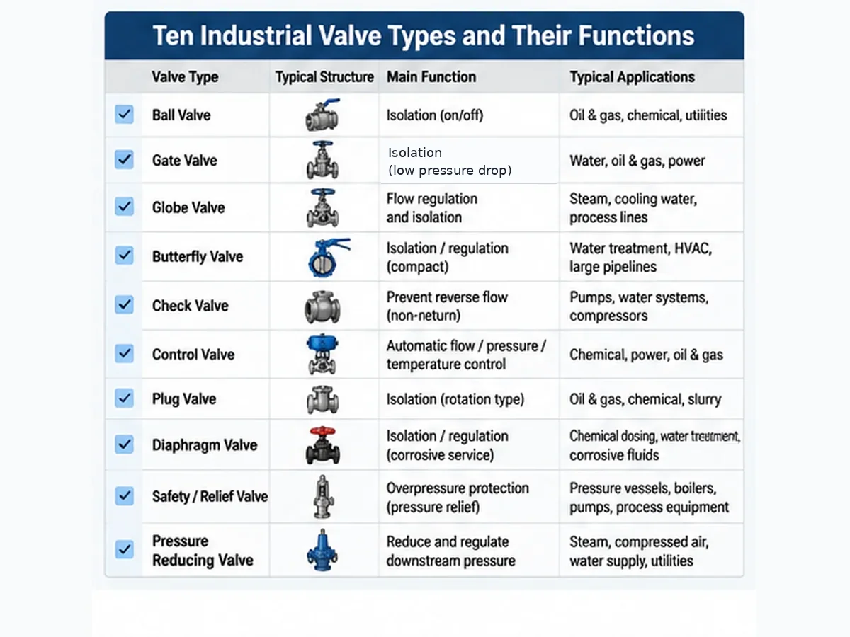
The ten categories in this guide are not all the same kind of classification. Ball, gate, globe, butterfly, plug and diaphragm primarily describe valve construction. Control valve describes a process-control role that may use different body designs. Check valve describes a non-return function. Safety/relief valve and pressure reducing valve describe pressure-management duties. A project specification should state both the required system function and the proposed construction where relevant.
How to Match Valve Types with Industrial Applications
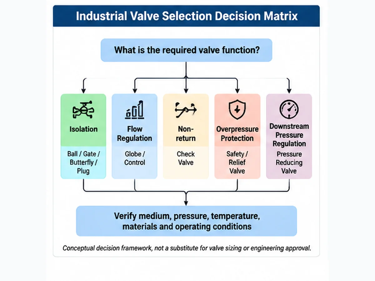
The table below provides preliminary candidates, not universal recommendations. Different process lines within the same industry may require different designs.
| Industrial application | Common valve candidates | Main selection considerations |
|---|---|---|
| Pipelines pétroliers et gaziers | Ball, gate, check, plug | Pressure, medium, leakage, isolation and reverse-flow duty |
| Traitement chimique | Ball, plug, diaphragm, control | Composition, concentration, corrosion, temperature and sealing |
| Traitement de l'eau | Butterfly, gate, check, ball | Water quality, solids, flow, pressure and maintenance |
| Power generation | Opcule, soupape, clapet anti-retour, régulation | Steam conditions, temperature, pressure drop and cycling |
| Mining and slurry | Specialized plug and other solids-service designs | Abrasion, particle size, solids loading and erosion |
| HVAC and cooling | Butterfly, ball, control | Flow regulation, pressure loss and operation |
| Air comprimé | Ball, pressure reducing, check | Supply pressure, leakage and downstream requirements |
| Pressure equipment | Safety/relief devices | Overpressure scenarios and relieving capacity |
Industrial Valve Function Selection: Which Type Should You Consider?
Identify the required duty before selecting a construction. Similar-looking valves may perform different functions, and a product name alone does not establish suitability.
| Fonction requise | Primary candidates | Typical duty | Key engineering check |
|---|---|---|---|
| Isolation de conduite | Ball, gate, butterfly, plug | Open or close a flow path | Shut-off requirement, pressure and temperature |
| Régulation de débit | Globe, control | Adjust process flow | Flow characteristic, pressure drop and controllability |
| Automatic process control | Vanne de régulation | Maintain flow, pressure or temperature | Process data, sizing inputs and actuator requirements |
| Prévention du reflux | Clapet anti-retour | Restrict reverse flow | Minimum flow, closing behavior and pressure surge |
| Protection contre les surpressions | Safety/relief device | Discharge fluid during an overpressure event | Relief scenario, set pressure and required capacity |
| Downstream pressure reduction | Vanne de réduction de pression | Maintain lower downstream pressure | Inlet variation, outlet target and flow range |
| Corrosive-fluid isolation | Compatible ball, plug or diaphragm designs | Isolate chemically aggressive media | Compatibility of all wetted components |
| Solids-containing service | Specialized plug or other engineered designs | Handle suspended solids | Particle size, concentration, erosion and clearances |
Three distinctions matter: Isolation is not the same as continuous process control. Pressure reduction is not overpressure protection. A check valve is not a positive isolation device.
Five Factors to Consider Before Selecting an Industrial Valve
1. Understand the medium
Identify liquid, gas, steam or multiphase service; chemical composition and concentration; suspended solids; corrosive or erosive behavior; and any tendency to crystallize, foul or polymerize. These properties affect body, trim, seat, packing, gasket and lining selection.
2. Confirm pressure and temperature
Review normal, minimum, maximum and design conditions. The pressure-temperature rating of the complete valve assembly must suit the intended service. Pressure class alone does not establish suitability for a particular temperature or medium.
3. Define the required function
Determine whether the duty is isolation, throttling, automatic process control, reverse-flow prevention, overpressure protection or downstream pressure regulation. Similar end connections do not make different valve functions interchangeable.
4. Evaluate materials and sealing
Review body, trim, seat, seal, stem packing, gasket and lining/coating materials as applicable. Consider chemical compatibility, temperature, pressure, wear, leakage criteria and the full service environment rather than relying on a material grade alone.
5. Review operation, testing and documentation
Confirm manual or automated operation, operating frequency, actuator/fail-position requirements, installation space, orientation, specified pressure and seat tests, inspection scope, traceability and project documentation. Check the relevant industrial valve standards guide alongside the project specification; verify the applicable edition and scope before assigning acceptance criteria.
Material, Seat and Sealing Review Before Valve Specification
Material selection should cover the complete wetted assembly rather than the valve body alone. Different components may have different compatibility and operating limits.
| Composant | What to review | Information required |
|---|---|---|
| Corps | Corrosion resistance, strength and pressure-temperature suitability | Medium composition, design conditions and material specification |
| Ball, disc or plug | Corrosion, erosion and surface damage | Fluid properties, solids and operating frequency |
| Tige ou arbre | Mechanical loading and corrosion | Differential pressure, operating torque and environment |
| Seat/seal | Chemical compatibility, temperature and shut-off performance | Medium, temperature and leakage acceptance criteria |
| Garniture de tige | External leakage control and temperature compatibility | Emission requirements, temperature and cycle frequency |
| Joint | Compatibility and joint sealing | Flange specification, temperature and pressure |
| Membrane | Chemical resistance, flexing and fatigue | Concentration, pressure cycling and replacement needs |
| Lining | Chemical resistance, adhesion and mechanical integrity | Fluid chemistry, temperature, velocity and solids |
Material review questions
- What is the exact medium and concentration?
- Are impurities, suspended solids or multiple phases present?
- What are the normal, minimum and maximum temperatures?
- Can the fluid cause corrosion, erosion, swelling or degradation?
- Are frequent cycles, partial opening, cleaning chemicals or flushing fluids relevant?
- What external leakage and shut-off requirements apply?
A material should not be approved solely because it is commonly used in the same industry. Compatibility must be assessed against the complete service environment and project requirements.
Which Operating Data Can Change the Valve Selection?
| Service input | Pourquoi c'est important | Potential selection impact |
|---|---|---|
| Fluid phase | Liquid, gas, steam and multiphase fluids behave differently | Changes flow calculation and design review |
| Minimum and maximum flow | Valve must accommodate the required operating range | Influences capacity and control range |
| Pression différentielle | Determines pressure loss across the valve | Affects operating forces, noise and cavitation risk |
| Température de fonctionnement | Influences material and sealing performance | May change body, seat, packing and gasket selection |
| Fluid composition | Compatibility varies with composition and concentration | May require alternative alloys, linings or seals |
| Suspended solids | Particles can cause erosion, blockage or seat damage | May favor specialized internal designs |
| Fréquence de fonctionnement | Repeated operation affects wear and maintenance | Influences construction and actuator review |
| Required shut-off | Duties have different allowable leakage criteria | Changes seat design and test requirements |
| Orientation d'installation | Some designs have installation restrictions | Affects valve type and arrangement |
| Failure position | Automated valves may need a defined response on loss of power or signal | Influences actuator and control configuration |
For a preliminary review, provide valve function/type, medium and phase, normal/minimum/maximum flow, normal and design pressure, operating and design temperature, inlet/outlet pressure where relevant, size, class, end connection, materials, operation method and project inspection requirements. Control valves, pressure reducing valves and pressure-protection devices require additional application-specific calculations and inputs before final sizing or approval.
Common Industrial Valve Selection Risks and How to Verify Them
| Potential problem | Possible cause | What to verify |
|---|---|---|
| Fuite au siège | Incompatible seat, damaged sealing surfaces or unsuitable differential pressure | Seat material, leakage criteria and test basis |
| External stem leakage | Packing incompatibility, installation issue or excessive cycling | Packing specification, emission requirement and maintenance arrangement |
| Excessive pressure drop | Unsuitable flow path or sizing | Flow rate, valve geometry and allowable pressure loss |
| Cavitation or flashing | Pressure recovery and process conditions | Inlet/outlet pressure, vapor pressure and fluid temperature |
| Coups de bélier | Unsuitable check-valve closure or rapid flow change | Transient analysis and closing characteristics |
| Disc or seat erosion | High local velocity, abrasive particles or prolonged throttling | Flow conditions, solids and operating position |
| Actuator fails to operate | Incorrect torque assumptions or insufficient supply | Required torque, differential pressure and available power/air |
| Diaphragm damage | Chemical incompatibility, excessive temperature or fatigue | Diaphragm material, cycles and process conditions |
| Downstream pressure instability | Incorrect pressure reducing valve selection or varying inlet/flow | Inlet range, outlet target and minimum/maximum flow |
| Inadequate pressure protection | Incorrect relief scenario or insufficient capacity | Overpressure study, required capacity and discharge conditions |
A failure symptom alone does not establish the root cause. Investigation should use the valve datasheet, inspection findings, operating records and applicable engineering calculations to distinguish design limitations, material/component selection, installation, operation and maintenance issues.
Practical Application Review Scenarios
The following are generic engineering review scenarios, not Raymon Valve customer case histories. They show how an application label should be translated into verifiable selection inputs.
Low-flow check valve instability
Problème : A check valve selected mainly by line size may operate unstably when the actual flow is below the range needed to keep the disc or closure element in a stable position. Why it matters: Repeated movement can contribute to chatter, wear and premature component damage. Verification: Review minimum and normal flow, velocity, valve orientation, closure design and the system’s start-up and shutdown cases. Where transient effects are credible, obtain a system-level assessment rather than relying only on a steady-state valve selection.
Correct nominal size but unsuitable control performance
Problème : A control valve specified from the pipeline nominal size without process sizing may have an unsuitable capacity or operating characteristic. Why it matters: The valve may operate near an undesirable travel range or create excessive pressure drop, noise, cavitation or flashing risk. Verification: Require minimum, normal and maximum flow cases, upstream and downstream pressure, temperature, fluid properties, allowable pressure drop, control objective and noise limits before confirming valve size or trim.
Material certificate without component-level identity checks
Problème : A material test certificate may be present, but the receiving inspection does not reconcile the certificate, heat number and physical component markings. Why it matters: A document alone does not prove that the delivered component is the same item represented by the record. Verification: Review traceability across the purchase order, material certificate, heat/lot identification and inspection records; apply PMI only where required by the approved inspection plan. PMI does not replace the full material certificate or heat-treatment records.
Pressure test passed but application approval remains open
Problème : A shell or closure pressure test is treated as proof that the valve is suitable for every aspect of the service. Why it matters: A pressure test addresses specified test boundaries and acceptance criteria; it does not independently establish material compatibility, control performance, fire-safe qualification or fugitive-emission performance. Verification: Map each project requirement to its own design review, test, inspection or certification evidence in the approved ITP and purchase specification.
What Technical Evidence Should an Industrial Valve Supplier Provide?
A technically acceptable quotation should be supported by documents that show whether the proposed construction matches the purchase specification. The required evidence depends on valve type, project specification and inspection level.
| Evidence/document | Ce que cela aide à vérifier | Procurement review |
|---|---|---|
| Approved valve datasheet | Main design and operating requirements | Confirm all technical fields are completed |
| Dessin d'ensemble | Dimensions, face-to-face and connections | Check installation and piping compatibility |
| Material Test Certificates (MTCs) | Material identity and reported test results | Match heat numbers and specified grades |
| Bill of Materials (BOM) | Components and material allocation | Review body, trim, seat and sealing materials |
| Pressure test reports | Results of specified pressure tests | Confirm scope and acceptance criteria |
| Inspection and Test Plan (ITP) | Inspection stages and witness/hold points | Match project inspection requirements |
| NDT reports | Specified non-destructive examinations | Check method, extent and acceptance basis |
| PMI reports | Material identification where specified | Confirm component coverage and traceability |
| Dimensional inspection | Conformité dimensionnelle | Compare with approved drawings and tolerances |
| Actuator documentation | Actuator data and configuration | Verify torque, supply and fail-position requirements |
| Deviation list | Differences from the specification | Obtain written technical disposition |
| Final documentation dossier | Required manufacturing and inspection records | Confirm document index and delivery scope |
Questions for supplier technical evaluation
For background on production stages and manufacturing documentation, see the industrial valve manufacturing process. Request order-specific records rather than assuming a general process description proves a particular product capability.
- Does the proposed valve meet each mandatory datasheet requirement?
- Are body, trim, seat, packing and gasket materials identified?
- Are substitutions or technical deviations proposed?
- Are specified inspection and testing activities included?
- Can material traceability be demonstrated where required?
- Are drawings and documents subject to approval before manufacturing?
- Are special service requirements addressed?
- Is the final documentation scope included in the quotation?
Evidence note: A document title alone is not proof of compliance. Review the actual report, component coverage, traceability, acceptance criteria and relationship to the approved purchase specification.
How to Normalize Industrial Valve Supplier Quotations
Compare technical compliance before commercial prices. A lower quotation may exclude testing, documentation, actuator accessories or project-specific requirements.
| Comparison item | Fournisseur A | Fournisseur B | Review result |
|---|---|---|---|
| Type et construction de la vanne | Record offered design | Record offered design | Confirm functional equivalence |
| Pression et température de conception | Record values | Record values | Check against datasheet |
| Matériaux du corps et de la garniture | Record grades | Record grades | Verify material compliance |
| Seat and packing | Record materials | Record materials | Check compatibility |
| Raccords d'extrémité | Record standard/dimensions | Record standard/dimensions | Confirm piping interface |
| Leakage requirements | Record criteria | Record criteria | Identify deviations |
| Actionneur et accessoires | Record configuration | Record configuration | Confirm operating requirements |
| Tests et inspection | Record included scope | Record included scope | Identify exclusions |
| Documentation | Record deliverables | Record deliverables | Compare dossier scope |
| Delivery and commercial terms | Record confirmed terms | Record confirmed terms | Compare on the same basis |
Use consistent technical bid statuses:
- Compliant: meets the specified requirement with supporting information.
- Deviation: differs from the requirement and needs written review.
- Clarification Required: information is insufficient to determine compliance.
- Not Included: explicitly excluded from the quotation.
- Not Applicable: does not apply to the proposed valve or project scope.
Do not treat a blank field as compliant. Resolve technical deviations before commercial normalization and purchase order approval.
Industrial Valve RFQ Checklist
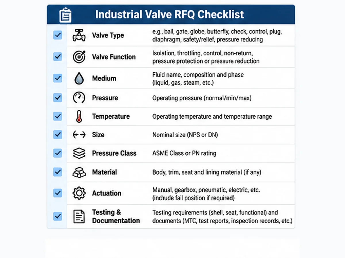
A complete RFQ helps manufacturers evaluate the application and prepare technically comparable quotations.
| RFQ field | Information to provide |
|---|---|
| Fonction/type de vanne | Isolation, throttling, control, non-return, pressure protection or pressure reduction; proposed design |
| Fluide | Name, composition, concentration and phase |
| Conditions de fonctionnement | Normal and minimum/maximum pressure, temperature and flow |
| Design conditions | Specified design pressure and temperature |
| Size and rating | NPS or DN; ASME Class or PN |
| Raccordement d'extrémité | Flanged, threaded, welded or other; applicable dimensions/standard |
| Matériaux | Body, trim, seat, packing, gasket and lining as applicable |
| Actionnement | Manual, gearbox, pneumatic, electric or hydraulic; accessories and fail position |
| Leakage | Required shut-off/leakage acceptance criteria and test basis |
| Tests et inspection | Specified shell, seat, functional tests, ITP, witness points and any NDT/PMI |
| Documentation | MTCs, drawings, test reports, inspection records and final dossier |
| Exigences spéciales | Fire-safe, fugitive emission, sour service, cryogenic, anti-static or third-party inspection where applicable |
The manufacturer should identify technical deviations and confirm the proposed construction against the complete datasheet and purchase specification. If data is unavailable, list it as an open clarification rather than assuming compliance.
Related Raymon Valve resources
- Review the industrial valve product range
- Compare valve functions and operating duties
- Review industrial valve pressure testing requirements
Technical References for Further Review
The following resources provide additional technical context for valve function, construction and selection. They are general references, not proof of compliance or performance for any Raymon Valve product or project.
- Emerson – Control Valve Handbook, 6th Edition: reference material on control-valve functions, characteristics, actuators, accessories and engineering data.
- Spirax Sarco – Isolation Valves: Linear Movement: background on gate, globe, piston and diaphragm valve construction and isolation duty.
- Spirax Sarco – Isolation Valves: Rotary Movement: background on ball and butterfly valve construction, applications and selection factors.
Always confirm the applicable standard edition, jurisdiction, purchaser requirements and project specification before using a general reference to approve a valve design or test scope.
Conclusion: Select Industrial Valves According to Their Actual Applications
The ten valve types discussed here perform different functions across industrial systems. Ball, gate, butterfly and plug valves are common isolation candidates; globe and control valves support flow regulation; check valves restrict reverse flow; safety and relief devices provide overpressure protection; and pressure reducing valves regulate downstream pressure.
The correct choice depends on the required function, medium, pressure, temperature, materials, sealing requirements and operating conditions. Engineers should prepare a complete valve datasheet rather than select equipment by nominal size or industry alone. Manufacturers should identify the proposed construction, materials, operating requirements, testing scope, documentation and any technical deviations before final approval.
Foire aux questions
1. Which industrial valves are commonly used across different industries?
Ball, gate, globe, butterfly, check, control, plug, diaphragm, safety/relief and pressure reducing valves are commonly used in industrial systems. These categories describe different constructions or functions and are not all mutually exclusive classifications.2. Which valve types are commonly used in oil and gas applications?
Ball, gate, check and plug valves are common candidates for selected pipeline and process duties. Control valves and pressure-protection devices are also used where process regulation and equipment protection are required. Final selection depends on service conditions and project specifications.3. What is the difference between isolation valves and control valves?
Isolation valves are primarily intended to open or close a flow path. Control valves automatically adjust flow resistance to regulate a process variable such as flow, pressure or temperature. Their design, sizing inputs and operating duties differ.4. Which valves are suitable for water treatment plants?
Butterfly, gate, ball and check valves are commonly considered in water treatment systems. Selection depends on pipeline size, water quality, solids content, pressure, flow requirements and maintenance conditions.5. Which valve types are used in steam applications?
Gate and globe valves are used in selected steam isolation and regulation duties. Control valves and pressure reducing valves may be used for automated regulation or downstream pressure control. Pressure-temperature ratings and steam-service requirements must be verified.6. What information is required to select an industrial valve?
Typical inputs include valve function, medium, normal and design pressure, operating and design temperature, flow, nominal size, pressure class, end connection, body and trim materials, sealing requirements, operation method, testing and documentation requirements.
Need Help Reviewing an Industrial Valve Application?
Industrial valve selection involves more than matching a product name to an industry. The valve function, process medium, pressure, temperature, material compatibility, sealing requirements and operating conditions all influence the proposed construction.
For a preliminary technical enquiry, EPC contractors, project engineers and procurement teams can submit the available process data and identify any unresolved specification fields. Product-specific suitability and manufacturing scope must be confirmed against the exact model and approved project requirements.
For a preliminary project review, please submit:
- Valve datasheet or technical specification.
- Medium composition and operating conditions.
- Valve size, pressure class and end connection.
- Body, trim, seat and sealing requirements.
- Manual or automated operation requirements.
- Applicable testing, inspection and documentation requirements.
If some information is unavailable, identify the missing fields for technical clarification.Submit Your Industrial Valve RFQ
Engineering Note: This article provides general industrial valve application guidance for preliminary engineering evaluation, supplier comparison and RFQ preparation. Application examples and selection tables are indicative, not approved project specifications. They do not establish universal material compatibility, pressure-temperature limits, leakage performance or suitability for every operating condition. Final selection, sizing, material approval, pressure protection and testing requirements must be confirmed against the project datasheet, applicable standards, engineering calculations and purchase specification.
Author: Raymon Valve Technical Content Team. Technical review status: No named engineering reviewer has been confirmed for this article.
 French
 English
 German
 Arabic
 Spanish
 Italian
 Portuguese
 Russian