
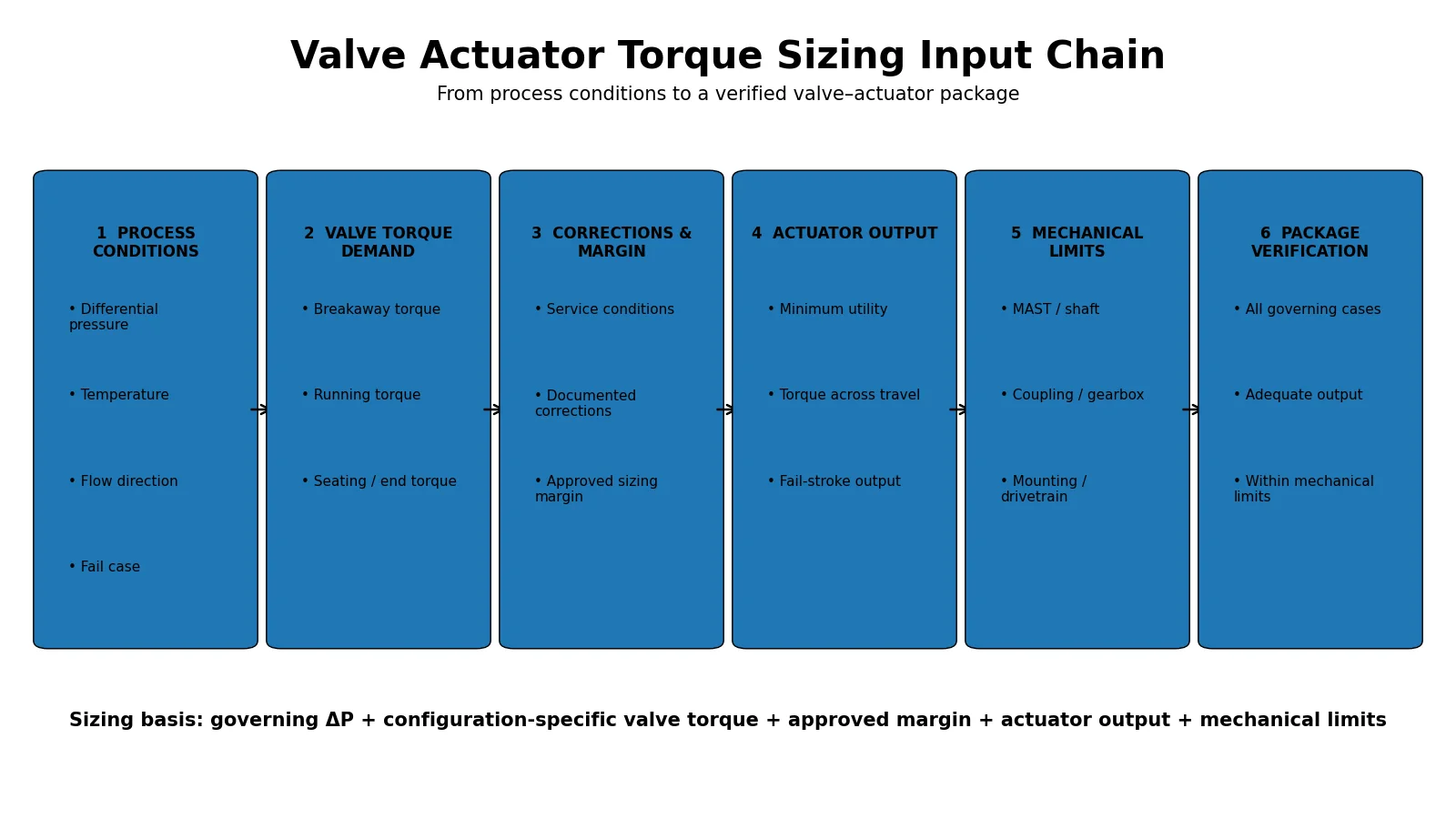
A valve actuator should not be selected from valve size or pressure class alone. For a part-turn valve, the sizing basis should compare configuration-specific valve torque demand at the relevant positions and directions with the actuator output available under the governing utility condition. The review normally includes breakaway, running and seating torque, worst-case differential pressure, approved service corrections and sizing margin, fail action, and the allowable torque of the valve stem, shaft, coupling and mounting system. This guide shows how to normalize those inputs for RFQ and technical-bid review.
Valve Actuator Torque Sizing Is a Load-Matching Exercise
Actuator sizing is fundamentally a load-matching problem. The engineering question is not simply how much torque an actuator can produce. The real question is whether the selected actuator can provide adequate output at every governing point of travel and during every required operating or failure case without overstressing the valve or drivetrain.
For part-turn assemblies, the actuator model should come at the end of this review—not at the beginning. A description such as “8-inch Class 300 ball valve” does not by itself establish actuator torque. Seat construction, valve design, differential pressure, temperature, operating direction and configuration-specific manufacturer torque data all matter.
For the broader selection route beyond torque matching, see the Руководство по выбору привода. For complete integrated assemblies, see Клапанные агрегаты с приводом.
Breakaway, Running and Seating Torque Do Not Represent the Same Load
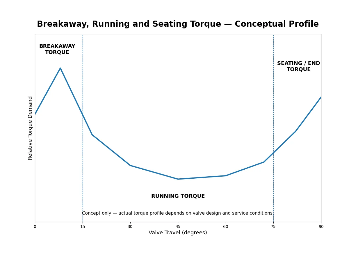
A single torque value rarely describes the complete operating duty of a part-turn valve. Different loads can govern initial movement, mid-stroke travel and end-of-travel seating. Actuator output may also vary through the stroke, so valve demand and actuator capability should be compared at corresponding positions and directions.
Breakaway / Unseating Torque
Breakaway torque is associated with initiating movement from a stationary position. In ISO 5115 terminology for part-turn valve actuation, breakaway torque is tied to the maximum differential-pressure operating case and can refer to break-to-open or break-to-close torque. For a closed isolation valve, the relevant load can be influenced by seat or seal friction, differential-pressure loading, stem or shaft friction and other configuration-specific effects.
Breakaway torque can become the controlling requirement even when the running load is lower. However, it should not automatically be assumed to be the highest load for every valve. The controlling condition depends on the valve design, pressure condition, operating direction and manufacturer data.
Running Torque
Running torque is the torque required while the valve moves between its end positions. It may include stem or shaft friction, bearings, seals, pressure-induced loading and, where relevant, fluid-dynamic forces. It should not automatically be treated as one constant value through the complete 0° to 90° travel.
Seating / End-of-Travel Torque
As the valve reaches the seated position, additional torque may be required to establish the intended shut-off condition. The important question is whether the actuator has adequate output at the specific end of travel where that load occurs. A package can fail a torque review even if a headline actuator torque is higher than a valve torque number quoted elsewhere.
Dynamic Torque Where It Matters
For some valve designs, particularly butterfly valves, fluid forces can introduce a significant position-dependent dynamic torque component. That load may depend on flow, differential pressure, valve angle, disc geometry and direction. Product-specific hydrodynamic or dynamic-torque data are therefore preferable to assumptions based on nominal size.
See the dedicated Butterfly Valve Actuator Sizing guide for a deeper treatment of differential pressure, flow cases and valve-demand versus actuator-output profiles.
Worst-Case Differential Pressure Must Be Defined Before Torque Is Reviewed
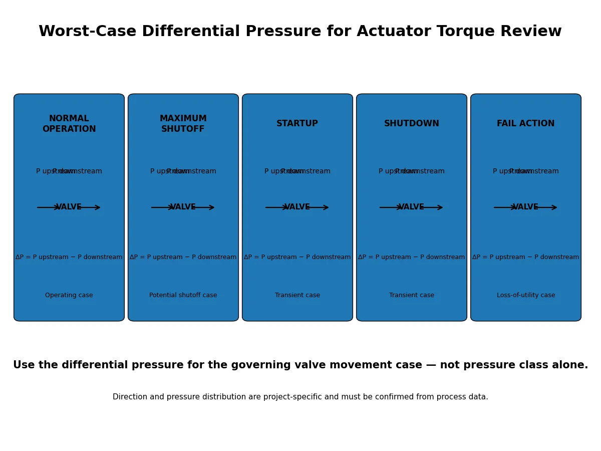
Differential pressure is one of the most important actuator-sizing inputs. Maximum system design pressure is not automatically the differential pressure acting across the valve during the movement that controls actuator sizing.
Maximum System Pressure Is Not Automatically the Actuator Sizing ΔP
Relevant pressure cases can include normal opening, normal closing, maximum shutoff, startup, shutdown, reverse differential pressure and the required fail action. Each case should identify the upstream and downstream pressure when valve movement is required.
Pressure class remains an important equipment specification field, but it does not define the actual pressure difference acting across the valve during each operating case.
Build Operating Cases Instead of Using One Pressure Number
| Operating Case | Upstream Pressure | Downstream Pressure | Differential Pressure | Direction | Required Valve Action |
|---|---|---|---|---|---|
| Normal opening | Project data | Project data | Рассчитать | Opening | Move to required position |
| Normal closing | Project data | Project data | Рассчитать | Closing | Move to required position |
| Maximum shutoff | Project data | Project data | Рассчитать | Project-defined | Open or close as required |
| Startup / shutdown | Project data | Project data | Рассчитать | Project-defined | Required transient action |
| Действие при отказе | Project data | Project data | Рассчитать | Fail direction | Reach required safe state |
Build the Valve Torque Basis From Configuration-Specific Data
The valve supplier should provide torque data for the exact configuration being offered. Data from another valve size, seat design, product series or pressure condition should not silently be transferred to the proposed valve.
A useful torque submission identifies, as applicable:
- valve type, model or series and nominal size;
- pressure rating and seat or seal construction;
- break-to-open and break-to-close torque;
- running torque in each relevant direction;
- end-to-open and end-to-close or seating torque where applicable;
- the differential pressure, temperature and direction associated with those values;
- service correction factors already included in the supplied data; and
- the maximum allowable stem, shaft or drivetrain torque applicable to the package.
Minimum Data Required Before an Actuator Size Can Be Approved
A torque review should not progress to final actuator model approval until the governing process cases and the exact valve configuration are defined. At minimum, the technical file should identify the valve type and size, seat or sealing design, relevant pressure and temperature cases, the torque values or torque curve for the offered valve, the basis of any correction factors, the required fail position, the actuator type, the minimum and maximum available utility condition and the applicable mechanical torque limit.
How Service Conditions Can Change the Torque Basis
A valve torque value is meaningful only in the context of the condition for which it was developed. Temperature can change seal friction or material behavior. Differential pressure can change seat loading. Long idle periods, deposits, solids, fouling or corrosion products may also affect the operating basis for particular services.
Where a service correction is required, its source, basis and applicability should be documented. The RFQ should identify whether a supplier torque value is raw, service-corrected or already design-factored.
When Actuator Sizing Should Stop Pending Clarification
Some missing inputs change the governing load case. Final actuator approval should stop pending clarification when any of the following conditions apply:
- the offered valve configuration is not frozen or does not match the torque data provided;
- the maximum differential pressure during opening, closing or fail action is undefined;
- the supplier cannot state whether the torque values are raw, service-corrected or already design-factored;
- the required fail direction is not confirmed;
- minimum pneumatic, hydraulic or electrical utility at the actuator is not defined;
- the actuator output curve or position-dependent output data are unavailable where needed;
- MAST or another controlling drivetrain torque limit has not been established; or
- the project specification requires a sizing method, margin or acceptance criterion that has not yet been reconciled with the supplier calculation.
These hold points separate a reviewable engineering basis from a quotation that only lists an actuator model.
Safety Factor Is Not a Universal Number
A sizing margin is often used so that the design does not depend on exact equality between predicted valve torque and actuator output. The problem begins when one generic multiplier is treated as a complete sizing method for every valve.
What the Margin Is Trying to Address
Depending on the project, the margin may address torque uncertainty, manufacturing variation, operating-condition variation, friction changes, utility uncertainty or other explicitly defined allowances. The applicable method should come from the project specification, responsible engineering discipline, valve manufacturer, actuator manufacturer or another approved design basis.
Why “Valve Torque × 1.5” Is Not a Complete Sizing Method
If supplier torque data are already corrected for a governing differential pressure, temperature and design allowance, an additional unexplained multiplier can double-count conservatism. Conversely, a nominal torque value with no documented service basis may not be adequately covered by an arbitrary generic factor.
Avoid Double-Counting Conservatism
The exact sequence can vary by project, but the calculation should expose each assumption rather than hide all conservatism inside one final number.
Calculation Framework — Not a Universal Formula
Corrected valve torque = Base valve torque × Applicable documented correction factor(s)
Required actuator torque basis = Corrected valve torque × Approved sizing safety factor
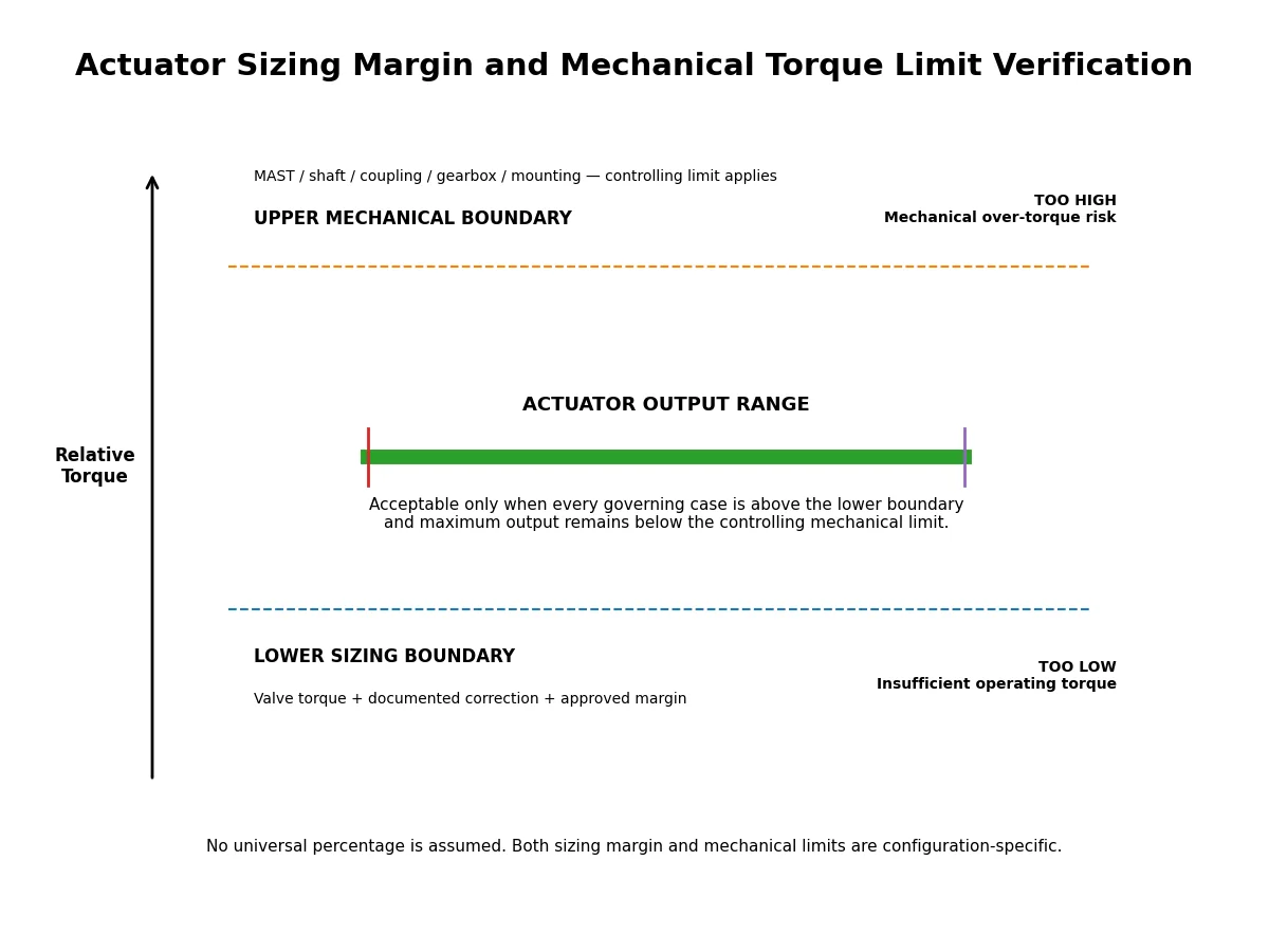
The selected actuator must then provide output above that required torque at the governing travel position and minimum available supply condition, while its maximum transmitted torque remains below the controlling mechanical limit.
ISO 5115 uses the term sizing safety factor (SSF) for the numerical factor applied to valve operating torque when selecting an actuator. This does not create one universal SSF for every project; the approved value and correction basis still need to come from the applicable project or supplier methodology.
Match Valve Torque Demand Against Actuator Output Across the Stroke
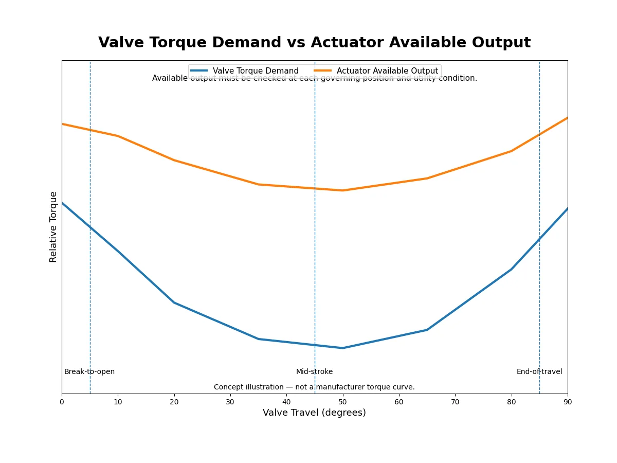
Once the valve torque basis is established, compare it with actuator output at corresponding positions and directions. The governing utility condition must be used, and the fail stroke must be checked separately where applicable.
Pneumatic Double-Acting Actuators
Catalogue torque at a convenient nominal air pressure is not enough if the plant cannot guarantee that pressure at the actuator inlet when the valve must move. ISO 5115 distinguishes minimum operating pressure—the pressure the actuator manufacturer says is required to operate the actuator—from minimum supply pressure—the minimum pressure the purchaser can actually provide at the actuator inlet. The sizing check should use the governing available supply condition, then compare opening and closing output against the corresponding valve demand. Maximum available air pressure should also be reviewed because it can increase the torque transmitted into the valve and drivetrain.
Spring-Return Actuators
Spring-return actuators require separate review of the powered stroke and the spring stroke. Start, mid-stroke and end torque can differ, so the selected spring set, mounting orientation and failure direction must be defined. A fail-closed package must have adequate closing output under the specified loss condition; fail-open duty requires the opposite review.
Electric Actuators
Relevant inputs can include output torque, torque limiting or torque-switch settings, operating speed, motor and gearbox arrangement, duty requirements, cycling frequency, electrical conditions and any required stored-energy or fail-safe function.
For technology selection outside the torque-matching calculation, see Pneumatic vs Electric Valve Actuator.
Minimum Required Torque Is Only Half of the Check
Preventing undersizing is only one side of actuator selection. A larger actuator can produce more torque than the valve stem, shaft, key, coupling, gearbox or mounting arrangement should receive.
Check Maximum Allowable Stem or Shaft Torque
The valve supplier should identify the applicable allowable stem, shaft or drivetrain torque for the proposed configuration. The term MAST is commonly used for maximum allowable stem torque, but terminology and the controlling component can vary by manufacturer and design.
The complete torque path can include the valve stem or shaft, key or drive connection, coupling, gearbox, bracket or mounting arrangement and actuator interface. The controlling approved limit governs.
Check Maximum Actuator Output
At minimum utility there must be adequate actuator output to move the valve. At maximum relevant utility—or at the maximum actuator output condition—the package should remain within the approved mechanical limits or use a verified limiting arrangement that protects those components.
Do Not Confuse ISO 5211 Attachment Requirements With Valve Operating Torque
ISO 5211 addresses the attachment interface between part-turn industrial valves and actuators. It supports mechanical interface definition, but it does not replace the configuration-specific breakaway, running or seating torque required by a particular valve under its actual pressure and service condition.
Where a separate metallic mounting kit is used to transmit torque between the valve and actuator attachment, the applicable mounting-kit requirements should also be reviewed. ISO 5640:2024 covers metallic mounting kits within its stated part-turn scope and explicitly excludes control valves. Interface compatibility and operating torque are related package checks, but they are not the same calculation.
Valve Torque vs Actuator Output Verification Matrix
| Travel / Operating Case | Valve Torque Basis | Service Correction | Approved Margin | Required Torque | Actuator Available Output | Mechanical Limit | Review |
|---|---|---|---|---|---|---|---|
| Break-to-open | Supplier data | Documented | Project basis | Рассчитать | Governing utility | Проверить | Pass / Review |
| Run-to-open | Supplier data | Documented | Project basis | Рассчитать | Across travel | Проверить | Pass / Review |
| End-to-open | If applicable | Documented | Project basis | Рассчитать | End position | Проверить | Pass / Review |
| Break-to-close | Supplier data | Documented | Project basis | Рассчитать | Relevant position | Проверить | Pass / Review |
| Run-to-close | Supplier data | Documented | Project basis | Рассчитать | Across travel | Проверить | Pass / Review |
| Seat / end-to-close | Supplier data | Documented | Project basis | Рассчитать | End position | Проверить | Pass / Review |
| Действие при отказе | Governing case | Documented | Project basis | Рассчитать | Loss-condition output | Проверить | Pass / Review |
Normalize Supplier Torque Data Before Comparing Bids
Two actuator quotations can look similar while using different torque assumptions. Procurement and engineering teams should normalize the sizing basis before comparing package size, cost or margin.
| Параметр сравнения | Supplier A / B Must State | Почему это важно |
|---|---|---|
| Источник крутящего момента клапана | Exact valve model, size, seat/design and torque reference | Prevents use of generic or mismatched torque data. |
| Pressure basis | Governing upstream/downstream pressure and differential pressure for each movement case | Ensures both bids are sized to the same process load. |
| Torque corrections | Temperature, service, aging or other correction factors and whether already included | Prevents hidden assumptions and double-counting. |
| Запас по размеру | Margin or factor used and its project/vendor basis | Allows like-for-like comparison rather than comparing final actuator sizes only. |
| Actuator output basis | Output across travel at the stated minimum utility condition | Confirms the actuator is being compared at the governing supply condition. |
| Действие при отказе | Fail-open / fail-close case and available output during the loss condition | Verifies that the required safe-state movement is actually covered. |
| Maximum output check | Maximum actuator output at maximum relevant utility or limiting setting | Supports over-torque review against MAST and other drivetrain limits. |
| Mechanical limits | MAST and any lower shaft, key, coupling, gearbox or mounting limit | Confirms the package is not accepted only on minimum torque adequacy. |
| Evidence supplied | Torque table/calculation, actuator data, output curve and deviations | Creates an auditable technical-bid basis before purchase approval. |
Common Valve Actuator Sizing Errors
- Starting from valve size, class or one headline torque value. These do not define the complete configuration-specific load through travel.
- Using design pressure instead of the governing differential-pressure case.
- Applying an unexplained sizing factor to torque data whose correction basis is unknown.
- Comparing valve demand with actuator output at nominal rather than minimum available supply.
- Checking minimum output but not the upper mechanical limit, fail stroke or maximum actuator output.
Valve Actuator Torque Sizing RFQ Checklist

| RFQ Field | Почему это важно |
|---|---|
| Valve type and exact configuration | Defines the torque-data source. |
| Nominal size and rating | Identifies the offered valve. |
| Seat / sealing design | Can affect operating load. |
| Medium and relevant composition | Supports service review. |
| Minimum / normal / maximum temperature | Establishes operating envelope. |
| Upstream and downstream pressure cases | Required for differential-pressure review. |
| Maximum shutoff differential pressure | Defines a possible governing movement case. |
| Flow / pressure direction | Identifies directional loading. |
| Breakaway, running and seating torque | Defines starting, travel and end-position loads. |
| Torque data assumptions and service corrections | Makes supplier basis traceable and avoids double-counting. |
| Project sizing margin | Defines the approved design allowance. |
| MAST / allowable shaft or drivetrain torque | Establishes the upper mechanical boundary. |
| Actuator type and configuration | Determines the output methodology. |
| Minimum and maximum utility | Defines minimum capability and maximum transmitted load. |
| Положение при отказе | Defines the loss-condition movement case. |
| Required travel time | Affects actuator and accessory selection. |
| Cycle frequency / duty | Supports operational suitability review. |
| Actuator output curve or table | Enables position-by-position comparison. |
| Mounting arrangement | Confirms mechanical compatibility. |
| Required calculation and test records | Defines technical approval evidence. |
What Evidence Should Be Approved Before Purchase Order Release?
Before technical release, the buyer should be able to trace the proposed actuator back to the valve load cases and the process conditions that generated those loads. Depending on the project, the approval package may need to identify the valve torque data or calculation, governing differential-pressure cases, service corrections, agreed sizing margin, actuator datasheet, actuator output curve, minimum and maximum utility basis, fail-action verification, allowable stem or drivetrain torque, mounting arrangement, deviations and required functional verification.
A useful approval record should also state which operating case governs the selected actuator, which mechanical limit governs the upper torque boundary, and which assumptions remain open. This makes later design review, commissioning or supplier change control much easier than an approval based only on the actuator model number.
For inspection planning, document review and final dossier requirements, see the industrial valve inspection and ITP guide.
For a project-level review route, see Обзор крутящего момента привода.
Final Engineering Decision
A suitable actuator is not simply the unit with the largest torque number. For a part-turn valve, the selected package should maintain adequate actuator output above the confirmed valve torque requirement for each governing operating and failure case, using the approved sizing basis and the relevant minimum utility condition.
At the same time, maximum actuator output must remain compatible with the allowable torque of the valve stem or shaft and the other components in the torque-transmission path.
Request Actuator Torque Review
Send the valve type and exact configuration, size and pressure class, seat design, medium, operating temperature, upstream and downstream pressure cases, maximum operating or shutoff differential pressure, valve torque data, allowable stem or shaft torque, minimum and maximum utility supply, required fail position, travel time, operating frequency and preferred actuator type.
Submit these inputs together with the valve torque table or calculation and the proposed actuator datasheet. A project-specific review should identify the governing torque case, the sizing assumptions, the applicable utility basis, the fail-action requirement, the upper mechanical torque limit and any data gaps that must be closed before package approval.
Request Actuator Torque ReviewЧасто задаваемые вопросы
What is breakaway torque in a valve?
Is breakaway torque always higher than running torque?
What safety factor should be used for valve actuator sizing?
Should an actuator be sized using design pressure or differential pressure?
What is MAST and why does it matter?
Can actuator size be selected from valve size and pressure class?
Does ISO 5211 determine the required valve operating torque?
- ISO 5115:2023 — Industrial valves — Part-turn valve actuation
- ISO 5211:2026 — Industrial valves — Part-turn actuator attachments
- ISO 5640:2024 — Industrial valves — Mounting kits for part-turn valve actuator attachment
ISO 5115:2023 supports the part-turn valve actuation sizing and information-responsibility framework used in this article. ISO 5211:2026 addresses actuator attachment interfaces and reference interface/coupling torques rather than the operating torque of a specific valve. ISO 5640:2024 addresses metallic mounting kits within its stated scope and excludes control valves. None of these standards proves that a specific Raymon Valve product or future order complies; the applicable edition, purchaser options and project precedence must be confirmed for the actual order.
 Russian
  English
  German
  Arabic
  French
  Spanish
  Italian
  Portuguese