
Инжиниринг регулирующих клапанов
Control Valve Cavitation vs Flashing: Pressure Recovery, Damage Patterns, Sizing and Mitigation
Cavitation and flashing both begin when liquid pressure falls enough for vapor to form, but they differ in what happens next. In cavitation, vapor bubbles collapse as pressure recovers; in flashing, vapor persists downstream. The distinction changes the damage mechanism and the appropriate mitigation strategy. A reliable assessment must consider local pressure recovery, fluid properties and the complete operating range—not merely the inlet and outlet pressure difference. This guide explains the evidence and sizing inputs needed to compare valve designs and prepare a defensible RFQ.
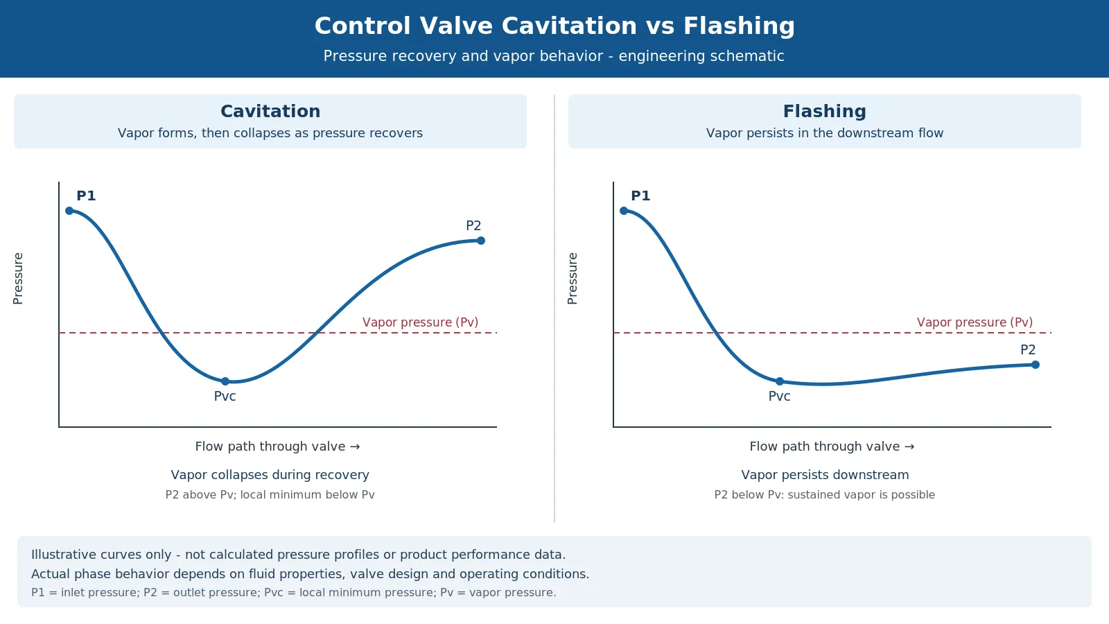
Cavitation vs Flashing: The Engineering Difference
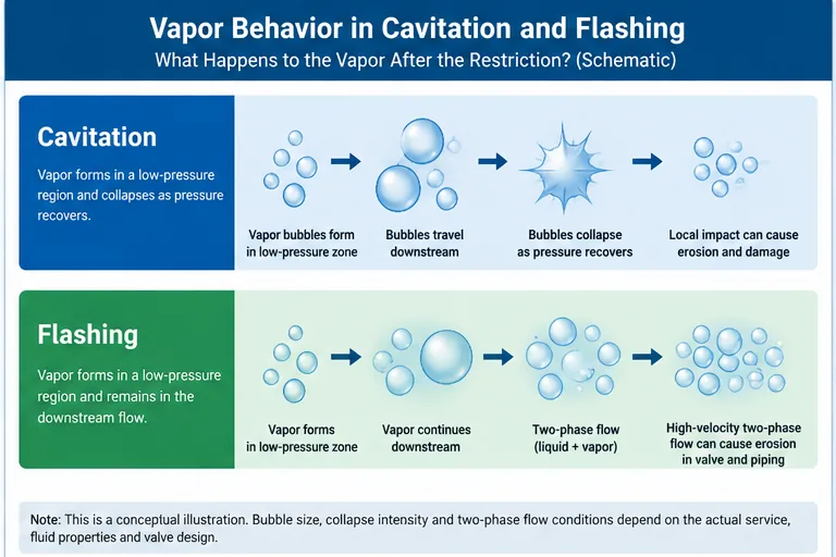
The key question is not simply whether vapor forms. It is what happens to that vapor after the liquid passes through the restriction.
| Инженерный вопрос | Cavitation | Flashing |
|---|---|---|
| What initiates the phenomenon? | Local liquid pressure falls sufficiently for vapor to form. | Local liquid pressure falls sufficiently for vapor to form. |
| What happens after the restriction? | Pressure recovery causes vapor bubbles to collapse. | Vapor persists as the downstream flow remains in a two-phase condition. |
| Primary damage concern | Localized bubble-collapse impact, erosion and possible vibration. | Sustained high-velocity liquid–vapor flow and associated erosion. |
| Typical design direction | Control harmful pressure recovery or distribute pressure drop. | Manage two-phase velocity, erosion exposure and downstream piping conditions. |
| Can material selection alone solve it? | No. Hydraulic conditions still matter. | No. Flow conditions and erosion exposure still matter. |
| What must be checked? | Vapor pressure, recovery characteristics and operating cases. | Downstream phase condition, flow capacity, velocity and erosion risk. |
A valve may experience cavitation at one operating point and flashing at another. Minimum, normal and maximum flow must be assessed with their corresponding pressures and temperatures, rather than treating the service as a single fixed condition.
For available product constructions, see Регулирующие клапаны. This comparison addresses the hydraulic problem rather than replacing product-specific sizing.
How Pressure Recovery Creates Cavitation or Flashing
The Vena Contracta and Local Minimum Pressure
As liquid accelerates through a control-valve restriction, static pressure decreases. The lowest pressure occurs in the region of greatest flow contraction, commonly described by the vena contracta. Pressure then recovers as the flow decelerates downstream.
- P1: upstream pressure.
- P2: downstream pressure.
- Pv: liquid vapor pressure at the relevant temperature.
- Pvc: local pressure near the vena contracta.
- Pressure recovery: the increase in static pressure after the local minimum.
If local pressure falls sufficiently, vapor can form even when measured downstream pressure is above vapor pressure. Subsequent recovery determines whether the bubbles collapse.
Cavitation: Vapor Forms and Collapses
Cavitation occurs when vapor forms in a low-pressure region and subsequently collapses as pressure rises. Bubble collapse can generate intense localized pressure effects. Repeated exposure may damage trim or pressure-containing surfaces, particularly where the flow directs collapsing vapor toward a solid boundary.
The location and severity depend on valve geometry, flow direction, operating conditions and fluid properties. Not every cavitating valve shows identical damage, and the onset of cavitation is not automatically the onset of unacceptable erosion.
Flashing: Vapor Remains Downstream
Flashing occurs when the pressure reduction produces vapor that continues into the downstream flow because the prevailing conditions do not support complete condensation. The resulting liquid–vapor mixture may have a much greater volumetric flow than the original liquid stream.
This can increase velocity and create erosion concerns in the valve outlet and downstream piping. Reducers, elbows and other exposed components may require review; a trim-only solution can leave the downstream problem unresolved.
Why Outlet Pressure Alone Is Insufficient
A downstream pressure above vapor pressure does not, by itself, prove cavitation is absent. The local pressure inside the valve may fall below vapor pressure before recovering. Conversely, downstream pressure below vapor pressure is an important indication of sustained vapor formation for a liquid that can flash under the stated conditions.
The actual phase behavior must be evaluated using fluid composition, temperature and thermodynamic properties. Multicomponent fluids and existing two-phase inlet conditions require particular care.
A Three-Step Hydraulic Review
- Can vapor form locally? Evaluate local pressure behavior against the relevant vapor-pressure characteristics using the applicable sizing method and valve data.
- What happens after pressure recovery? Determine whether downstream conditions support vapor collapse or persistent two-phase flow.
- What is the consequence for the selected construction? Evaluate capacity, noise, erosion exposure, trim design and downstream piping separately.
Repeat the review at minimum, normal and maximum flow, as well as start-up or upset conditions where relevant. Changes in pressure or temperature can change the phase behavior even when the valve and piping remain unchanged.
Границы применения: Any simplified pressure curve illustrates the mechanism only. It is not a calculated pressure profile for a specific valve and cannot establish cavitation severity, flashing rate or allowable operating limits.
Damage Patterns: What Can Inspection Reveal?
Cavitation and flashing can produce different damage tendencies, but surface appearance is evidence—not a complete root-cause diagnosis.
Cavitation Damage
Cavitation may produce localized pitting, roughened surfaces and progressive erosion where bubble collapse occurs near exposed materials. Trim components, seating regions and body surfaces may be affected depending on the flow path.
Abnormal noise, vibration, unstable control or loss of shutoff performance may accompany the problem, but none is unique to cavitation. Operating records and physical inspection must be considered together.
Flashing Damage
Flashing is more commonly associated with sustained high-velocity two-phase erosion. Damage may extend through the outlet flow path and downstream piping, especially where flow direction changes or local velocity increases.
Corrosion, solids, droplets and other erosion mechanisms may also contribute. A liquid–vapor mixture does not automatically establish the sole cause of material loss.
A Practical Inspection Approach
| Observation | Possible interpretation | Verification needed |
|---|---|---|
| Localized pitting near a high-energy flow region | Consistent with cavitation exposure | Operating pressures, temperature, fluid properties and pressure recovery |
| Directional erosion in the outlet or downstream piping | Consistent with sustained high-velocity flow, potentially flashing | Phase condition, velocity, flow direction and material loss history |
| Abnormal noise or vibration | May accompany cavitation or other flow-induced problems | Operating case, acoustic/vibration assessment and mechanical inspection |
| Repeated trim damage after replacement | The original hydraulic or service cause may remain | Sizing review, trim design, operating range and failure history |
| Downstream elbow or reducer damage | Flow concentration or two-phase erosion may contribute | Piping geometry, velocity, phase behavior and inspection records |
Do Not Diagnose the Failure From Appearance Alone
A common troubleshooting mistake is to identify cavitation from a pitted surface and order harder replacement trim without checking the operating data. Corrosion, solid-particle erosion, liquid impingement or combined mechanisms may produce similar evidence. Record the damaged component, location, flow direction, pressures, temperatures, fluid composition and time in service. If the mechanism remains uncertain, request a qualified failure analysis.
Another recurring concern is damage that reappears after replacement. Review the actual operating range and pressure recovery before assuming the new material or trim is defective. Replacing a component without addressing the service conditions may leave the cause unresolved.
Граница безопасности: If damage, leakage or vibration raises concern about pressure-boundary integrity, follow the plant’s isolation and inspection procedures. Do not continue operation based solely on a visual diagnosis or an assumption that the problem is harmless cavitation noise.
Which Sizing Inputs Determine the Risk?
Cavitation and flashing assessment belongs within the complete control-valve sizing process. The objective is not only to calculate flow capacity, but also to establish whether the selected construction can operate acceptably across the required range.
Minimum Process Data
- Fluid name, composition, phase and relevant impurities or solids.
- Minimum, normal and maximum flow rates, with units.
- Corresponding upstream and downstream pressures for each case, identified as absolute or gauge.
- Operating and design temperatures; vapor pressure and other required fluid properties.
- Density and viscosity where applicable.
- Pipe size, schedule and relevant inlet/outlet geometry.
- Control objective, required rangeability and expected operating position.
- Allowable noise, vibration or erosion-related requirements.
- Existing two-phase conditions and special service concerns.
- Required shutoff performance, material requirements, actuation and fail action where relevant.
Pressure Recovery Factors and Choked Flow
In the applicable liquid-sizing method, FL is the liquid pressure recovery factor for a valve without attached fittings. FLP is the combined liquid pressure recovery factor and piping geometry factor for a valve with attached fittings. FF is the liquid critical pressure ratio factor associated with fluid properties. These parameters have different roles and must be used with the correct equations and conditions.
They are not interchangeable cavitation-severity indices. FL and FLP also depend on the applicable valve configuration and opening; a single value cannot establish acceptable erosion, noise or vibration across the operating range. The manufacturer should provide the relevant coefficients for the proposed construction.
Choked flow is not the same thing as cavitation damage. Choked flow describes a flow-capacity limitation under the applicable conditions; cavitation and flashing describe phase behavior and associated damage mechanisms. Choked-flow prediction alone does not establish a damage rate or service life.
Applicable Sizing Standards and Their Limits
IEC 60534-2-1:2011, including its April 2015 corrigendum, provides sizing equations for fluid flow through industrial-process control valves under installed conditions. Its incompressible-flow equations are based on Newtonian-fluid hydrodynamics and are not intended for unrestricted application to non-Newtonian fluids, slurries, liquid-solid conveyance or complex mixtures. The published scope includes conditions under which non-vaporizing multicomponent liquid mixtures may be considered; applicability must be checked rather than assumed.
An already two-phase inlet or a flashing mixture outside the ordinary liquid method’s assumptions requires a suitable specialized assessment. IEC 60534-8-4:2015 addresses prediction of noise generated by liquid flow through control valves; a noise prediction is not a guarantee of erosion resistance, cavitation-free operation or service life.
The official IEC 60534-2-1 publication и IEC 60534-8-4 publication provide the relevant scope and edition records. Project specifications and exact-model manufacturer data remain necessary for final approval.
What the Sizing Review Must Establish
The calculation should establish required Cv or Kv for each operating case and identify the applicable flow regime. The review must then address cavitation or flashing risk, noise, operating position, control performance and downstream conditions. A capacity calculation alone does not establish acceptable erosion resistance or service life.
For severe liquid service, request the sizing basis, proposed trim construction, relevant coefficients and assumptions used in the cavitation/flashing assessment. If the fluid falls outside the chosen method’s assumptions, obtain a specialized review.
No final Cv, nominal size, trim stage count or allowable pressure drop can be determined from this article. For the complete calculation-input and review process, use the Руководство по подбору регулирующего клапана.
Operating-Case Matrix
Use actual project data for every case. The entries below identify required inputs; they are not example calculations.
| Operating case | Flow | P1 | P2 | Температура | Fluid properties | Required review |
|---|---|---|---|---|---|---|
| Минимум | Buyer data | Buyer data | Buyer data | Buyer data | Buyer data | Control stability and local pressure behavior |
| Нормальное | Buyer data | Buyer data | Buyer data | Buyer data | Buyer data | Capacity and cavitation/flashing assessment |
| Максимум | Buyer data | Buyer data | Buyer data | Buyer data | Buyer data | Capacity, velocity, noise and erosion exposure |
| Start-up / upset, if applicable | Buyer data | Buyer data | Buyer data | Buyer data | Buyer data | Separate engineering review |
A typical RFQ mistake is to provide only the normal-flow case. The supplier may calculate adequate capacity while an off-design case remains unreviewed. Ask for results at the corresponding pressures and temperatures, not a single design differential pressure applied to every flow.
Mitigation: Different Mechanisms Require Different Designs
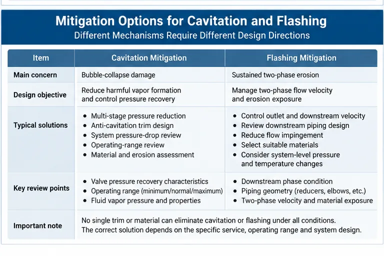
Cavitation Mitigation
For cavitating service, the objective is to reduce harmful vapor formation and collapse, or to control where and how pressure recovery occurs.
- Multi-stage pressure reduction: distribute the total pressure drop across engineered restrictions to limit severe local pressure reduction.
- Service-specific anti-cavitation trim: use flow paths and recovery characteristics appropriate to the operating conditions.
- System pressure-drop review: assess whether the pressure reduction can be allocated differently within the process.
- Operating-range review: check whether low-flow or off-design operation creates a more severe condition than the nominal case.
- Material and erosion review: select exposed materials using the actual service conditions; hardness alone does not remove the hydraulic cause.
The effectiveness of each option depends on the valve, fluid and operating conditions. No generic trim should be described as eliminating cavitation under all circumstances.
Flashing Mitigation
For flashing service, vapor may remain present downstream. A conventional anti-cavitation approach cannot be assumed to restore the liquid to a single phase.
- Manage outlet and downstream two-phase velocity.
- Review valve outlet geometry and downstream pipe sizing.
- Reduce severe local flow impingement where practical.
- Select materials and construction suitable for expected erosion and corrosion exposure.
- Review reducers, elbows and other downstream components.
- Consider system-level pressure and temperature changes where process design permits.
The correct solution may involve both the valve and surrounding piping. A trim-only quotation can be incomplete when the downstream system is exposed to persistent two-phase flow.
For a specific construction, review the Противокавитационный регулирующий клапан page and request confirmation of the proposed trim against the complete datasheet.
Mitigation Selection Matrix
| Условия эксплуатации | Main concern | Направление обзора |
|---|---|---|
| Local vapor formation followed by recovery | Bubble-collapse damage | Pressure recovery, staged reduction and anti-cavitation design |
| Sustained liquid–vapor flow downstream | High-velocity two-phase erosion | Outlet velocity, piping geometry and material exposure |
| Широкий рабочий диапазон | Different risk at different flow cases | Minimum/normal/maximum sizing and control review |
| Existing trim damage | Root cause may remain after replacement | Operating history, inspection and hydraulic reassessment |
| Corrosive or solids-containing fluid | Combined damage mechanisms | Material compatibility, erosion and process-condition review |
What Each Mitigation Option Must Demonstrate
| Предлагаемое направление | Intended purpose | What it does not establish | Свидетельство поставщика |
|---|---|---|---|
| Multi-stage pressure reduction | Reduce severe local pressure reduction and harmful recovery conditions | Does not guarantee cavitation-free operation at every flow | Sizing basis, operating-case review and trim construction |
| Anti-cavitation trim | Manage cavitation-related hydraulic behavior | Does not automatically solve persistent flashing | Applicable service limits and manufacturer assessment |
| Outlet / downstream velocity review | Reduce exposure to sustained two-phase erosion | Does not change the fluid’s thermodynamic phase condition by itself | Outlet conditions, piping review and relevant calculations |
| Material upgrade | Improve resistance to selected damage mechanisms | Does not remove the hydraulic cause | Material compatibility and service-specific justification |
| System pressure-drop redistribution | Change the pressure reduction imposed on the valve | May affect process control and other equipment | Process-engineering approval and revised operating cases |
How to Specify a Valve for an RFQ
A useful RFQ should allow suppliers to evaluate the same operating conditions and explain their proposed mitigation method. Asking only for an “anti-cavitation control valve” is not sufficient.
Required RFQ Information
| RFQ field | What the buyer should provide or request |
|---|---|
| Service and fluid | Medium, composition, temperature and relevant fluid properties |
| Рабочие режимы | Minimum, normal and maximum flow with corresponding P1/P2 |
| Производительность | Required flow and control range |
| Cavitation/flashing review | Manufacturer assessment of the relevant operating cases |
| Proposed trim | Construction, pressure-reduction approach and service limitations |
| Материалы | Body, trim, seat and other exposed material requirements |
| Noise and vibration | Project limits and required prediction or review method |
| Downstream conditions | Pipe size, reducers, elbows and potential two-phase exposure |
| Требования к герметичности | Required leakage performance and applicable acceptance basis |
| Документация | Sizing calculation, datasheet, technical deviations and agreed inspection/test scope |
Normalize Supplier Quotations
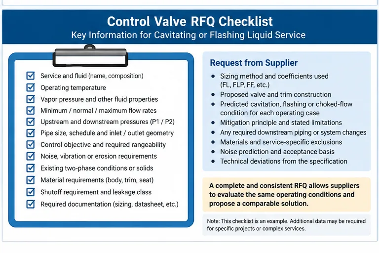
When comparing bids, request the same process cases and ask each supplier to identify:
- The sizing method and coefficients used.
- The proposed valve and trim construction.
- The predicted cavitation, flashing or choked-flow condition for each case.
- The mitigation principle and its stated limitations.
- Any required downstream piping or system changes.
- Materials and service-specific exclusions.
- Noise, inspection and documentation assumptions.
- Technical deviations from the purchase specification.
A recurring bid-review problem is that two suppliers quote the same nominal size but use different operating assumptions. Request a common case matrix and a calculation/deviation schedule before comparing price. This makes the comparison more meaningful than nominal size, pressure class and price alone.
Engineering Approval Gate
A proposed control valve should pass three separate reviews before technical approval.
HOLD Missing essential data: Do not finalize the valve size or trim when operating cases, fluid properties, pressure conditions or required control performance are incomplete. Request the missing datasheet information.
REVIEW Severe or uncertain service: Obtain additional engineering assessment when the service is close to saturation, includes existing two-phase flow, contains solids, has a large pressure reduction, or has a history of abnormal noise, vibration or repeated erosion. Confirm whether the proposed mitigation addresses cavitation, flashing or another damage mechanism.
APPROVE Documented technical basis: Proceed only when the selected construction has been reviewed against the complete operating envelope, sizing and mitigation assumptions are documented, material and downstream piping requirements are addressed, and technical deviations are accepted by the responsible project authority.
A product label such as “anti-cavitation” is not a substitute for this review. Final selection remains subject to confirmed project data, manufacturer calculations and applicable project requirements.
Ask for Control Valve Sizing Support
Send your control-valve datasheet with fluid composition, minimum/normal/maximum flow, corresponding inlet and outlet pressures, temperature, vapor-pressure data, pipe size and control objective. If the valve is already in service, include available damage photographs, inspection findings and operating history.
For severe liquid service, identify noise limits, material requirements, downstream piping conditions and project-specific documentation. These inputs allow the proposed sizing basis, trim construction and mitigation approach to be reviewed before quotation.
Final selection remains subject to confirmed project data, manufacturer calculations and applicable project requirements.
Submit Your Valve DatasheetЧасто задаваемые вопросы
What is the main difference between cavitation and flashing in a control valve?
Cavitation involves vapor formation followed by bubble collapse as pressure recovers. Flashing involves vapor that persists in the downstream flow. The distinction affects damage mechanisms and mitigation strategy.
Can a control valve cavitate when outlet pressure is above vapor pressure?
Yes. Local pressure inside the valve can fall below vapor pressure before recovering. Outlet pressure alone cannot establish whether cavitation occurs.
Does flashing always cause cavitation?
No. Flashing and cavitation both involve vapor formation, but cavitation requires subsequent bubble collapse. Persistent downstream vapor does not necessarily undergo that collapse.
Can anti-cavitation trim prevent flashing damage?
Not necessarily. Anti-cavitation trim manages cavitation-related hydraulic conditions. Flashing may require separate consideration of two-phase velocity, outlet geometry, materials and downstream piping.
What data is needed to size a control valve for cavitating or flashing service?
The review needs fluid properties, flow range, corresponding upstream and downstream pressures, temperature, vapor pressure, piping data and valve-specific sizing information. Complex or two-phase service may require additional data and a specialized method.
Can valve material alone prevent cavitation or flashing erosion?
No. Material selection can influence resistance to damage, but it does not remove the underlying pressure-recovery or two-phase flow conditions.
What should be included in an RFQ for severe liquid service?
Include all operating cases, fluid properties, piping conditions, required control performance, material requirements, noise limits, proposed trim review, sizing calculations and technical deviations. Suppliers should evaluate the same engineering basis.
Заключение
Cavitation and flashing should be evaluated as different hydraulic and phase-change conditions, not interchangeable names for high-pressure-drop service. Cavitation mitigation focuses on harmful vapor collapse and pressure recovery; flashing mitigation must address persistent two-phase flow and its effect on the valve and downstream system.
The practical sequence is: confirm the operating cases → evaluate phase behavior and pressure recovery → complete sizing → compare mitigation designs → review materials and downstream conditions → approve the documented solution.
For further technical resources, visit the База знаний.
Инженерные ограничения: This article provides general technical guidance. It does not establish a final Cv, valve size, trim selection, allowable noise level, material suitability or service-life prediction for a specific project.
 Russian
  English
  German
  Arabic
  French
  Spanish
  Italian
  Portuguese