
GATE VALVE ENGINEERING / FUNCTION & ISOLATION
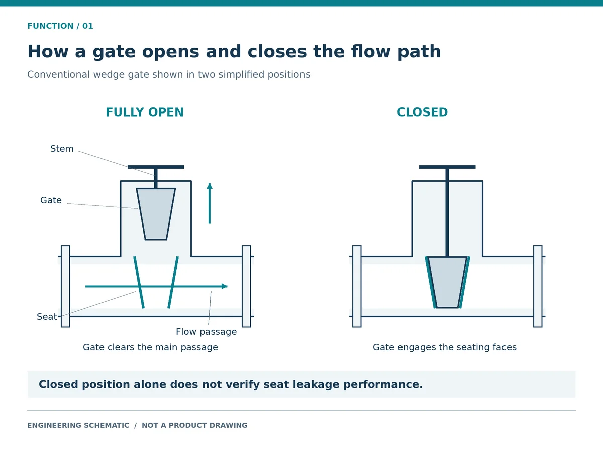
Gate valve functions center on starting, stopping and isolating pipeline flow. In a conventional wedge valve, the gate lifts clear of the passage to open it and engages the seats to close it. Through-conduit slab designs can instead align a port in the gate with the pipeline bore. Conventional gate valves serve fully open or fully closed duty; sustained throttling can damage seating surfaces. Selection therefore depends on the isolation direction, operating differential pressure, service conditions and leakage requirement.
IN THIS GUIDE
- What Are the Main Gate Valve Functions?
- How Does a Gate Valve Work?
- Why Are Gate Valves Generally Unsuitable for Throttling?
- What Does a Closed Gate Valve Actually Prove?
- Which Conditions Limit Gate Valve Functions?
- How Should Engineers Specify Gate Valve Functions?
- How Can Buyers Verify a Supplier’s Isolation Proposal?
- Request a Gate Valve Selection Review
- Gate Valve Functions FAQ
What Are the Main Gate Valve Functions?
Starting and Stopping Pipeline Flow
Opening a gate valve permits flow when a driving pressure difference exists; closing engages its seats. The valve does not generate flow or independently maintain a downstream pressure setpoint.
AVK’s technical explanation identifies conventional gate valves as isolation devices rather than regulating valves.
Review the API 600 gate valve where the specified steel wedge-gate construction is relevant. It is not the default for every isolation duty.
Isolating Equipment and Pipeline Sections
Isolation is one of the main gate valve functions. Its use for equipment or pipeline isolation depends on fluid hazards, pressure sources, potential leakage and site requirements.
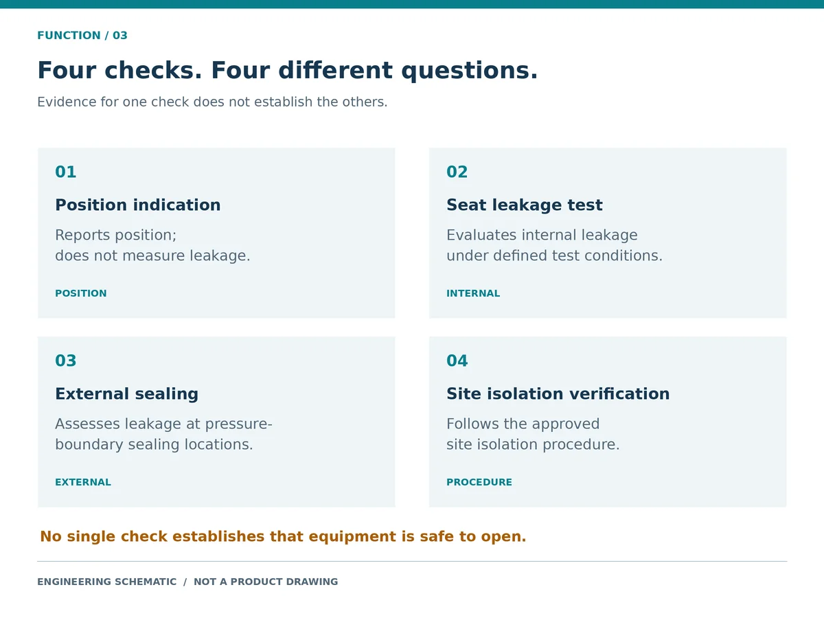
A closed valve alone does not establish safe conditions for opening equipment. The approved procedure must address stored pressure, alternative flow paths and verification; additional barriers or positive isolation may be required.
HSE HSG253, The Safe Isolation of Plant and Equipment (second edition, 2006) addresses process-isolation arrangements and procedures, not individual valve qualification.
Providing a Low-Resistance Flow Path When Fully Open
An open gate valve can provide a relatively unobstructed passage. Pressure loss depends on actual bore, geometry, flow and fluid properties; nominal size alone proves neither full-bore dimensions nor a pressure-drop value.
Use this table to match required gate valve functions with design capabilities and acceptance evidence.
On smaller screens, scroll the table horizontally to view all columns.
| Erforderliche Funktion | Gate-valve screening decision | What to verify |
|---|---|---|
| Ein-/Aus-Absperrung | A suitable candidate | Service envelope, materials, operating differential pressure and leakage acceptance |
| Low resistance when open | Often a useful characteristic | Actual bore and manufacturer flow data |
| Continuous flow regulation | Generally unsuitable for conventional designs | A specifically supported regulating design, or a suitable alternative valve |
| Automatic reverse-flow prevention | A conventional gate valve does not provide automatic check action | Whether a separate check valve is required |
| Isolation in both directions | Depends on the design | Directional restrictions and sealing evidence for each required direction |
| Double block and bleed | Cannot be inferred from the product name | Defined isolation function, seat arrangement, cavity connections and test evidence |
| Schweinpassage | Requires a purpose-suitable construction | Minimum bore, internal profile and compatibility with the specified pig |
How Does a Gate Valve Work?
How the Stem Moves the Gate
The operator moves the gate approximately perpendicular to flow. Handwheels and gearboxes commonly convert rotation into gate travel; actuated arrangements must deliver the required motion and load.
Rising-stem arrangements visibly change stem position; non-rising arrangements reduce external travel and may use a separate indicator. Position indicators report mechanical position and require confirmation against the valve’s actual travel arrangement.
What Happens in the Open and Closed Positions
The illustrated wedge gate lifts out of the main passage. In a through-conduit slab design, a hole through the gate aligns with the body bore when open; the gate’s solid section blocks the passage when closed. Wedge, parallel and expanding designs establish seating contact differently. See the port-alignment explanation in SLB’s GROVE G4N technical brochure (PDF); its model-specific performance claims are not generalized here.
How Seats and Packing Serve Different Functions
Gate and seat contact limits internal leakage. Packing or another stem seal limits external leakage at the stem penetration; the body and bonnet joint also form part of the pressure boundary.
Internal seat leakage and external packing leakage require separate checks.
Why Are Gate Valves Generally Unsuitable for Throttling?
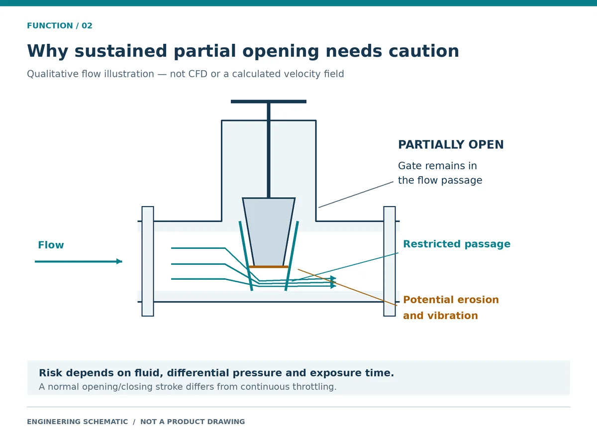
Partial opening restricts the passage. Depending on fluid conditions and pressure drop, local high velocity, vibration and erosion can damage the gate or seats and impair later shut-off.
A percentage-open indication does not establish a controllable flow characteristic. Adding a positioner or electric actuator does not qualify an isolation gate valve for continuous regulation.
Passing through intermediate positions during an approved stroke differs from continuous throttling. For regulating duty, provide flow range, upstream/downstream pressures, temperature, fluid properties and control objective.
What Does a Closed Gate Valve Actually Prove?
Closed Position and Seat Leakage Are Different Checks
A closed indication reports a position or operator endpoint, not leakage. Closure testing specifies medium, differential pressure, direction, duration and acceptance criteria.
“Tight shut-off” alone is an ambiguous RFQ requirement. Specify allowable leakage and the test basis; the Ressource für Druckprüfungen von Ventilen explains the distinction. A shell test checks pressure-boundary integrity under the specified test conditions; a closure test checks seat leakage. Neither establishes continued sealing after installation or service exposure.
Illustrative inspection scenario: A closed indication is present, but the isolated section does not meet the site’s leakage or pressure criteria. Possible explanations include an indication/travel mismatch, deposits or damaged seating surfaces; the symptom alone does not identify the cause. Review the indication, service history and acceptance evidence under the approved isolation procedure. Escalate an unproved isolation to the responsible operator or engineer rather than applying additional force. HSE’s process-isolation guidance supports treating isolation verification as a separate task.
Bidirectional Isolation Requires Design Confirmation
Confirm isolation direction and supporting tests. A symmetrical body does not prove equal sealing in both directions; include pressure-reversal cases where relevant.
Double Block and Bleed Requires Specific Evidence
Define the required double-block-and-bleed function using the project specification, then verify seat action, cavity access and the corresponding tests. A cavity connection alone is insufficient evidence.
Cavity pressure management belongs in the design and operating review; no field venting sequence is prescribed here.
Which Conditions Limit Gate Valve Functions?
Differential Pressure and Operating Thrust
Pressure class is a rating designation, not a fixed allowable pressure: Class 150 does not mean a universal 150 psi limit. Determine allowable pressure from the applicable material group, temperature, standard and valve design. Review design pressure and temperature, including their coincident cases, for the body, bonnet, bolting, trim and seals; normal operating pressure alone is insufficient. ASME B16.34—Valves, Flanged, Threaded, and Welding End covers ratings and other construction requirements for valves within its scope. The official page currently lists the 2025 edition; confirm the contract edition and product applicability.
Match valve load, operator output, supply, stroke time and required failure response. Check load protection as well as adequate output; nominal valve size alone cannot determine actuator size.
Differential pressure is the pressure difference across the gate. The maximum opening or closing differential can differ from normal line pressure, particularly when one side is depressurized. Gate travel requires linear thrust; a multi-turn drive converts torque into that motion. Obtain the valve/drive load relationship rather than treating torque and thrust as interchangeable values.
Illustrative RFQ scenario: A powered valve is quoted against pressure class alone, while the required opening case has a pressurized upstream side and a depressurized downstream side. The class establishes neither the required breakaway load nor the available operator output. Request maximum operating differential, seat/construction details, torque or thrust data, supply limits, margin basis, stroke time and failure response before accepting actuator matching.
Temperature Changes and Binding Risks
Thermal expansion can alter clearances, seating contact and operating load. Provide minimum and maximum service temperatures, startup/shutdown cases and thermal cycles. Low-temperature material requirements and seal limits need their own review; a design pressure entry cannot resolve them.
Material and Seal Compatibility
Review body, gate, seats, stem, packing and gaskets against fluid composition, concentration, temperature, pressure, flow velocity, solids and cleaning chemicals. Where relevant, include pH, chlorides, H₂S and shutdown exposure. Identify the expected damage mechanism rather than assuming that a material name proves compatibility. Seats and trim affect shut-off and wear; stem and packing friction affect operating load; packing and gaskets also require temperature and chemical checks. Fire-safe and fugitive-emission requirements need separate configuration-specific qualification evidence.
Solids, Deposits and Seat Obstruction
Particles and deposits can obstruct travel or sealing. Specify solids concentration, size, abrasiveness, settling and cleaning needs; a knife-gate name alone does not establish slurry suitability.
Operating Frequency and Actuation Requirements
Specify cycling frequency, stroke time, feedback and utilities for powered operation. Assess hydraulic transients where relevant; multi-turn operation does not itself prevent water hammer.
Use the broader gate valve guide when these inputs require a complete construction and specification review.
How Should Engineers Specify Gate Valve Functions?
Prepare an RFQ that connects the requested function to acceptance evidence.
On smaller screens, scroll the table horizontally to view all columns.
| RFQ field | Information to provide | Review outcome |
|---|---|---|
| Funktion | Isolation location, normal position and required action | Agreed duty and operating philosophy |
| Fluid | Composition, phase, solids and contaminants | Material and construction review |
| Conditions | Operating/design pressures and temperatures; relevant transients | Confirmed service envelope |
| Operating differential | Maximum differential during opening and closing; possible reversal | Valve and operator load review |
| Schnittstellen | Size, rating, ends, orientation and available clearance | Compatible installation and access |
| Absperrung | Direction, leakage acceptance and test conditions | Comparable sealing commitment |
| Betrieb | Manual/actuated duty, frequency, time, supply and failure response | Defined package requirements |
| Nachweis | Drawings, IOM, tests, traceability and project-specific documents | Agreed acceptance and handover scope |
Mark unknowns “to be confirmed” and request explicit assumptions and deviations. Resolve those affecting isolation before approval. Special functions and qualifications need their own evidence.
How Can Buyers Verify a Supplier’s Isolation Proposal?
Compare the specified gate valve functions with the supplier’s statements and evidence using this matrix. Missing evidence is an open point, not automatic proof of unsuitability.
On smaller screens, scroll the table horizontally to view all columns.
| Supplier statement | Anzufordernder Nachweis | Question to close before approval |
|---|---|---|
| “Tight shut-off” | Agreed leakage acceptance, test procedure and applicable valve test record | Do the medium, pressure, duration and direction match the specified test basis? |
| “Operates at full pressure” | Maximum opening/closing differential and valve/operator load basis | Does “pressure” mean static line pressure or differential across the gate? |
| “Bidirectional” | Approved drawing, directional limitations and sealing test scope | Is isolation supported in both required pressure directions? |
| “Suitable for the medium” | Component material schedule and declared service limits | Were trim, packing, gaskets, contaminants and cleaning media reviewed? |
| “Automated isolation” | Valve/actuator matching data, supply assumptions and functional test scope | Are travel, operating time, load protection and required failure response defined? |
Request proposed configuration and exceptions at bidding; obtain configuration- or tag-linked acceptance records at handover. Functional testing checks travel and operation within its stated scope; it does not replace leakage testing. Material certificates, identification checks and specified NDE address different acceptance questions. Agree required procedures, witness/hold points and records in the inspection plan; a generic certificate does not close a configuration-specific requirement.
Example: Turning a Function Request into an RFQ
Illustrative case: A normally open clean-water line needs occasional isolation, without regulation or pig passage. Pressure, temperature, operating differential and leakage acceptance remain unknown. This supports initial screening only.
Required duty: normally open, occasional on/off isolation; no continuous throttling. Confirm the valve construction, materials and operator against the completed service datasheet. State maximum opening and closing differential pressure, permitted isolation direction, leakage acceptance and test basis, installation clearance, documentation scope and all technical deviations.
Reassess the valve function if continuous regulation, automatic reverse-flow prevention or a specified emergency action is added.
Request a Gate Valve Selection Review
For a review of gate valve functions in your application, send the isolation duty, medium, pressure, temperature, maximum operating differential, size and leakage requirement. Attach a datasheet or P&ID where available; mark unknown values. Include design conditions, rating, ends and actuation requirements.
Request the proposed construction, materials, operator assumptions, tests, documents and deviations in the quotation.
Gate Valve Functions FAQ
What Is the Main Function of a Gate Valve?
The primary gate valve functions are starting, stopping and isolating pipeline flow. The gate opens the passage or engages its seats, subject to the selected construction and specified leakage requirement. How Does a Gate Valve Stop Flow?
The stem moves the gate into the flow passage, where the closure and seats establish sealing contact. The mechanism creating that contact varies with the gate design. Can a Gate Valve Regulate Flow?
Conventional gate valves are generally unsuitable for continuous throttling. A regulating duty requires a design with supported flow-control performance and suitability for the actual operating conditions. Does a Closed Gate Valve Guarantee Zero Leakage?
No. A closed indication does not measure leakage. Specify the allowable leakage and test conditions, and follow the site’s isolation verification requirements. Can a Gate Valve Isolate Flow in Both Directions?
Some designs support bidirectional isolation. Confirm the specific seat arrangement, pressure restrictions and evidence for the directions required by the project. Does an Electric Actuator Make a Gate Valve Suitable for Control?
An electric actuator enables powered operation. Continuous control also requires suitable valve geometry, supported flow characteristics, operating-load capacity and a compatible control package.
Content attribution: Raymon Valve Technical Content Team. General engineering guidance; project-specific approval requires the responsible engineering review.
Technische Anmerkung: This article supports function screening and RFQ preparation. Its diagrams are simplified explanations, not model-specific drawings or test evidence. No operating limit, leakage result, certification or installed performance is established for an offered valve. Final selection and acceptance depend on the complete datasheet, applicable requirements, approved deviations and configuration-specific manufacturer evidence.
 German
 English
 Arabic
 French
 Spanish
 Italian
 Portuguese
 Russian