
A water pump discharge check valve prevents reverse flow and helps protect pumping systems during shutdown and changing operating conditions. Selecting the right valve requires evaluating flow range, pressure loss, closure characteristics, water hammer risks and installation orientation. Swing, dual plate and axial-flow designs offer different operating mechanisms, making model-specific hydraulic data essential for reliable selection.
This engineering guide explains how to compare water check valve constructions, evaluate minimum operating flow, review pump shutdown and water hammer risks, select materials, verify installation conditions and prepare a technically complete RFQ.
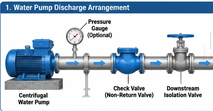
Scope: This article focuses on engineering selection for water pump discharge service. See the industrial check valve product range. This guide does not replace project-specific sizing or hydraulic transient analysis.
1. Why Check Valve Selection Matters in Water Pump Discharge Systems
A check valve permits forward flow and restricts reverse flow when the operating differential pressure changes. In a pump discharge system, this function is important during pump shutdown, power failure, pump trip and transitions between parallel pumps.
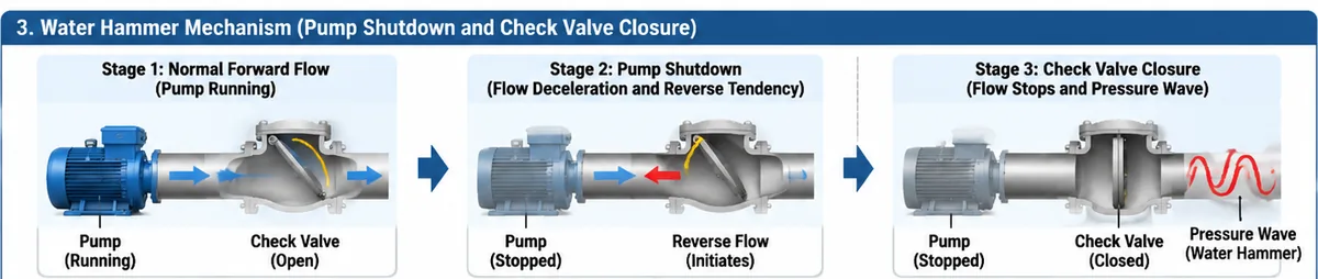
When a pump stops, the water column does not necessarily stop immediately. Fluid inertia, pump rotor coast-down, static head and pipeline characteristics determine how flow decelerates. If reverse flow develops before the check valve closes, subsequent closure can contribute to a hydraulic pressure transient.
Typical operating scenarios
- Normal pump operation: The valve should open adequately without unacceptable pressure loss.
- Low-flow operation: Review model-specific stability and minimum-flow information.
- Pump trip: Pump coast-down and system deceleration influence closure conditions.
- Parallel pumps: Other operating pumps can affect reverse-flow potential through an idle branch.
- Long discharge pipelines: Pipeline length, elevation, wave speed and boundary conditions may influence transient response.
A valve that matches the discharge pipe nominal diameter may still be unsuitable if its pressure loss, opening characteristics or closure response do not match the actual duty.
2. Main Types of Check Valves for Water Applications
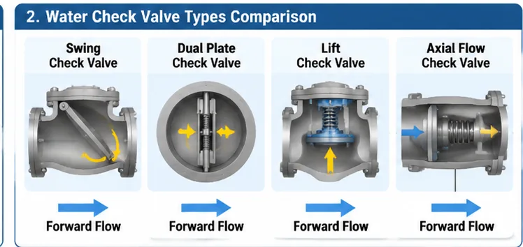
Different check valve constructions use different moving-element arrangements. Selection should consider the operating envelope, hydraulic behavior, available space, maintenance access and manufacturer limitations.
2.1 Swing Check Valves
A swing check valve uses a disc or clapper that pivots around a hinge or shaft. Forward flow moves the disc away from the seat, while reverse-flow conditions cause it to return toward the closed position. Review disc travel, hinge arrangement, minimum operating flow, pressure-loss data, permitted orientation and closing behavior.
2.2 Dual Plate Check Valves
A dual plate check valve uses two plates arranged around a central hinge. Spring assistance is common, but actual configuration and operating characteristics depend on the design. Confirm opening differential pressure, spring characteristics, flow passage, installation limitations and model-specific performance data. Do not assume every dual plate valve is automatically non-slam.
2.3 Axial Flow and Nozzle Check Valves
Axial-flow and nozzle-type check valves generally use an axially moving closure element. Spring assistance and internal flow geometry influence opening and closing behavior. Suitability must be established using the proposed model’s technical information.
2.4 Lift Check Valves
A lift check valve uses a closure element that moves away from its seat under forward differential pressure and returns toward the seat when the differential reverses. Suitability depends on body arrangement, flow conditions, installation orientation and manufacturer limitations.
Check Valve Construction Comparison
| Construction | Operating Mechanism | Considérations de sélection | Evidence to Request |
|---|---|---|---|
| Battant | Pivoting disc or clapper | Disc travel, flow stability, orientation and closure response | Sectional drawing, pressure-loss data and operating limits |
| Dual plate | Two plates around a central hinge, commonly spring-assisted | Spring characteristics, opening pressure and installation space | Spring arrangement, model data and installation instructions |
| Axial flow / nozzle | Axially moving closure element | Flow passage, spring response and dynamic performance | Performance data and applicable test evidence |
| Levée | Moving closure element | Orientation, pressure loss and moving-element stability | Approved orientation and model-specific technical data |
3. How to Select a Check Valve for Water Pump Discharge
Start with the pump and piping system rather than the product catalogue. Assess the proposed construction against the full operating envelope and consequences of reverse flow. The selected water pump discharge check valve must suit the actual pump duty, not simply the nominal pipeline size.
3.1 Confirm the Water Service
Identify whether the application involves raw water, potable water, cooling water, treated water, wastewater or reclaimed water. Water quality can affect material compatibility, seat selection, corrosion, erosion, fouling and maintenance. For water containing suspended solids, review flow passage, disc geometry, seat arrangement and cleaning access.
3.2 Establish Minimum, Normal and Maximum Flow
Assess minimum expected flow together with the model’s opening differential pressure and recommended operating range. For parallel-pump systems, consider individual and combined operation, standby transitions and potential reverse flow through an idle pump branch.
3.3 Review Pressure and Temperature
Confirm normal operating pressure, design pressure, minimum and maximum temperature, anticipated surge conditions and specified pressure class or PN rating. The applicable pressure-temperature rating depends on governing design standard, material group, temperature and valve construction.
3.4 Evaluate Pressure Loss
Request manufacturer pressure-loss or flow data for the proposed model and relevant operating range. Confirm units, fluid properties, test conditions and measurement basis before applying published data to the project calculation.
3.5 Confirm Installation Space and Orientation
Review face-to-face dimensions, end connections, lifting requirements, maintenance access and allowable installation orientation. Physical fit alone does not establish suitability.
Engineering decision: Final check valve selection requires the pump operating envelope, hydraulic conditions and exact valve model data. A generic recommendation based only on pipeline diameter is not sufficient.
4. Check Valve Sizing and Minimum Flow Verification
Check valve sizing is not simply a matter of selecting the same nominal diameter as the discharge pipe. The selected valve must provide adequate flow passage while maintaining acceptable pressure loss and stable operation across the expected range.
4.1 Minimum Flow Verification
Establish whether the proposed construction can operate reliably at the lowest expected forward-flow condition. Minimum operating flow is product-specific and should not be replaced with an assumed universal velocity. Confirm that the water pump discharge check valve remains stable across the expected operating flow range using the manufacturer’s minimum-flow and opening-pressure data.
| Required Input | Supplier Information to Request | Engineering Review |
|---|---|---|
| Minimum flow rate | Minimum recommended operating flow | Compare with pump operating envelope |
| Opening differential pressure | Opening or cracking pressure data | Check available differential pressure |
| Normal flow rate | Recommended operating range | Evaluate disc position and stability |
| Maximum flow rate | Maximum permitted conditions | Review velocity and pressure loss |
| Low-load operation | Applicable operating limitations | Assess partial-load and parallel-pump conditions |
If the supplier cannot provide model-specific minimum operating data, record the item as pending technical confirmation. Do not invent a universal minimum velocity or opening differential pressure.
4.2 Pressure Loss and Flow Stability
Review pressure-loss data at minimum, normal and maximum flow. Confirm units, test medium, reference density and measurement basis. A steady-state pressure-loss calculation does not establish transient closure performance.
For further engineering detail, read check valve sizing and stable-opening requirements.
5. Pump Shutdown, Reverse Flow and Water Hammer
Water hammer is a hydraulic transient caused by a change in fluid velocity. In a pump discharge line, a pump trip, power failure, rapid valve movement or other event may generate pressure waves. Check valve closure can interact with the moving water column and influence the transient response.
5.1 Why Pump Shutdown Can Cause a Closure Impact
Pump rotor coast-down, static head, fluid inertia and pipeline characteristics determine how the water column decelerates. If reverse flow develops before the valve closes, the closure element may move toward the seat while reverse velocity is developing. Pressure response depends on closure timing, reverse velocity, pipeline wave speed, boundary conditions and system configuration. Water pump discharge check valve performance during shutdown should therefore be reviewed against pump coast-down data and the hydraulic characteristics of the complete pipeline system.
5.2 Non-Slam Claims Require Evidence
Descriptions such as silent, fast-closing or non-slam should not be treated as guaranteed performance claims. Request information relevant to the proposed valve model and actual operating conditions.
| Élément de preuve | Information to Request | Objectif |
|---|---|---|
| Construction de la vanne | Sectional drawing and moving-element arrangement | Understand closing mechanism |
| Spring characteristics | Spring arrangement and technical data | Review spring-assisted closure |
| Operating range | Débit minimum, normal et maximum | Check applicability to pump duty |
| Closure characteristics | Model-specific test or performance data | Evaluate closing response |
| Perte de charge | Manufacturer pressure-loss data | Assess hydraulic impact |
| Test conditions | Test medium, flow, pressure and configuration | Determine evidence applicability |
Where transient behavior is critical, review supplier information together with pump coast-down data, pipeline geometry, static head and downstream pressure. A valve test under one operating condition cannot automatically establish performance in a different pumping system.
5.3 System-Level Transient Assessment
Where water hammer could threaten pipeline integrity or connected equipment, the responsible hydraulic engineer should assess the complete system. Depending on project complexity, this may require a transient model using pump characteristics, pipeline geometry, fluid properties, wave speed, boundary conditions and valve closure characteristics.
For further troubleshooting guidance, read check valve chatter and slamming diagnosis.
6. Installation Requirements for Water Check Valves
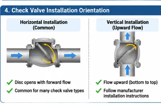
Correct installation is essential for reliable check valve operation. Permitted orientation and flow direction depend on the valve construction and manufacturer design.
6.1 Flow Direction
Verify the flow-direction marking on the valve body before installation. Incorrect orientation can prevent normal opening or compromise closure function.
6.2 Pipeline Alignment and Support
Check flange alignment, gasket arrangement, bolt tightening procedure and pipe support. Do not use the valve body to force misaligned piping into position.
6.3 Installation Orientation
Some check valve designs are intended primarily for horizontal installation, while others may permit specified vertical arrangements. Confirm whether the selected model is approved for upward or downward flow in the proposed orientation.
6.4 Maintenance Clearance
Provide sufficient space for cover removal, inspection and replacement of serviceable components. Consider lifting access, isolation, drainage and safe depressurization before maintenance.
Limites de sécurité : Inspection or maintenance must not begin until equipment has been isolated, depressurized and drained under approved lockout/tagout and work-permit procedures. Confirm trapped pressure cannot remain inside the valve or connected piping.
7. Materials, Seats and Water Quality
Material selection should reflect water chemistry, operating temperature, solids, corrosion exposure and project requirements. Body material alone does not establish suitability of the complete valve assembly.
| Composant | Considérations de sélection | Evidence to Confirm |
|---|---|---|
| Body and cover | Pressure-temperature rating, corrosion and mechanical requirements | Material specification and certificates where required |
| Disc or plates | Strength, wear, corrosion and moving-element compatibility | Material grade and construction drawing |
| Hinge, shaft or guide | Wear, alignment, corrosion and cyclic operation | Material and design details |
| Siège | Shut-off requirement, water chemistry, temperature and wear | Seat material and leakage acceptance criteria |
| Ressort | Corrosion, fatigue and operating temperature | Spring material and design information |
| Fasteners | Strength, corrosion exposure and joint requirements | Material grade and coating specification |
For potable water, verify applicable project and jurisdictional requirements for wetted materials, coatings and approvals. For wastewater or water containing solids, review erosion, deposits, fouling and cleaning access. No single seat material should be assumed suitable for all water services.
8. Standards, Inspection and Testing
Applicable standards depend on valve construction, waterworks or industrial service, connection configuration and purchase specification. A standard title does not establish that every check valve design is within its scope. Consult the official AWWA standards list for waterworks valve standards, the API standards updates for current API 594 notices and errata, and the ISO 5208:2015 standard page for metallic valve pressure-testing information. Always confirm the applicable edition and product-standard requirements in the project specification.
8.1 AWWA C508-25
AWWA C508-25 addresses swing-check valves for waterworks service. Verify exact size range, construction, end connections and service limitations against the controlled edition and project requirements. Public AWWA descriptions have shown inconsistent size-range information; therefore, this article does not use an unqualified size range as a procurement acceptance criterion.
8.2 AWWA C518-24
AWWA C518-24 addresses double-disc swing-check valves for waterworks service. Its published scope identifies 2-in. through 48-in. (50-mm through 1,200-mm) NPS. Confirm exact construction and service requirements against the standard and project specification.
8.3 API Standard 594
API Standard 594 covers check valves with specified flanged, lug, wafer and butt-welding configurations. Verify applicable edition, errata, valve type and connection arrangement before including it in a procurement specification. Do not assume every axial-flow or nozzle-type design is automatically covered.
8.4 Inspection and Testing Requirements
| Inspection or Test | Objectif | Evidence to Request |
|---|---|---|
| Material verification | Confirm specified component materials | Material certificates where specified |
| Visual inspection | Review manufacturing condition | Inspection records |
| Dimensional inspection | Verify specified dimensions | Dimensional inspection report |
| Shell pressure test | Evaluate pressure-containing body integrity | Pressure test record |
| Closure or seat test | Evaluate seating performance against specified criteria | Seat test record |
| Functional inspection | Review moving-element assembly and movement | Functional inspection record |
| Examen de la documentation | Verify purchase and traceability requirements | Final documentation package |
Testing boundary: Shell pressure testing evaluates pressure-containing integrity under specified test conditions. Seat testing evaluates closure performance against applicable acceptance criteria. Neither test alone proves dynamic water hammer performance during an actual pump trip.
Confirm applicable test standard, edition, test medium, pressure, duration, leakage acceptance criteria and witness requirements in the purchase specification. Additional NDT, PMI, coating inspection or third-party witness activities should be included only where required by the project ITP or contract.
9. Technical RFQ Checklist for Water Pump Check Valves
A complete RFQ should provide enough information for suppliers to assess the valve construction and identify missing engineering inputs. Use the following checklist during inquiry preparation and technical bid evaluation.
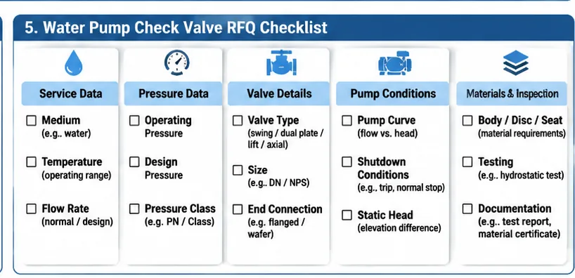
Minimum RFQ information
- Valve function and service description.
- Water type, composition and suspended solids.
- Minimum, normal and maximum flow rate.
- Normal and design pressure.
- Normal and design temperature.
- Valve size and pressure class or PN.
- End connection and applicable dimensional standard.
- Body, disc, seat, spring and fastener material requirements.
- Allowable pressure loss or hydraulic design criteria.
- Installation orientation and available space.
- Pump datasheet and performance curve.
- Pump trip, shutdown and transient requirements.
- Inspection, testing and documentation requirements.
- Quantity, delivery scope and technical deviation schedule.
Technical Deviations That Require Clarification
- Proposed valve construction differs from the specified design.
- Minimum operating flow has not been confirmed.
- Pressure-loss data is unavailable for the proposed model.
- Installation orientation differs from the project arrangement.
- Seat or spring material differs from the approved datasheet.
- Required inspection or testing has been excluded.
- Dynamic closure claims are not supported by applicable evidence.
- Applicable standards or editions are not clearly identified.
Record each deviation in the technical bid evaluation. Commercial comparison should proceed only after significant technical differences have been clarified.
10. Supplier Data and Engineering Approval
Before technical approval, request documentation that identifies the exact proposed model and the conditions under which its performance information applies.
| Document | Review Purpose | Approval Consideration |
|---|---|---|
| Technical datasheet | Confirm model, size, class, material and connections | All required fields completed |
| Dessin en coupe | Review disc, seat, hinge, spring and internal arrangement | Construction matches approved proposal |
| Dimensional drawing | Check face-to-face and installation envelope | Compatible with piping layout |
| Pressure-loss data | Assess hydraulic impact | Conditions and units are clear |
| Operating limitations | Review minimum and maximum flow conditions | Applicable to pump duty |
| Enregistrements de test | Review specified inspection and testing | Acceptance criteria and traceability available |
| Material documentation | Verify specified materials | Certificates meet purchase requirements |
| Instructions d'installation | Confirm orientation and maintenance requirements | Compatible with site arrangement |
Where the manufacturer cannot provide model-specific evidence for a critical operating condition, retain the item as an open technical deviation. Final approval should be based on the exact model, approved datasheet and project engineering review.
11. Common Check Valve Selection Mistakes
Choosing only by pipeline diameter
Problème : The selected valve matches the line size but has unsuitable flow characteristics.
Verification: Review minimum, normal and maximum flow, pressure loss and the manufacturer’s operating range.
Assuming every spring-assisted valve is non-slam
Problème : A marketing description is treated as proof of system-level transient performance.
Verification: Request model-specific closure data and review pump shutdown behavior with the responsible hydraulic engineer.
Ignoring low-load operation
Problème : The valve is evaluated only at the pump’s normal duty point.
Verification: Check minimum flow, partial-load operation and parallel-pump conditions.
Ignoring installation orientation
Problème : A valve is installed in an orientation not approved for its construction.
Verification: Review manufacturer instructions and the approved piping arrangement.
Accepting shell test results as proof of all performance
Problème : A pressure test record is treated as evidence of dynamic closure performance.
Verification: Review shell, seat, functional and dynamic evidence as separate requirements.
12. Final Selection Decision
A suitable water pump discharge check valve should satisfy the hydraulic, mechanical, installation and procurement requirements of the complete system. The selection process should not rely on a generic product label or a single operating point.
| Decision Area | Approval Question | Required Evidence |
|---|---|---|
| Hydraulic duty | Does the valve operate across the expected flow range? | Pump curve and model-specific operating data |
| Perte de charge | Is pressure loss acceptable? | Manufacturer flow or pressure-loss data |
| Closure behavior | Is reverse-flow and transient risk adequately assessed? | Closure information and system analysis where required |
| Matériaux | Are all wetted and moving components suitable? | Material specifications and certificates as required |
| Installation | Is the arrangement compatible with the approved piping layout? | Dimensional drawing and installation instructions |
| Qualité | Are inspection and testing requirements defined? | ITP, test records and documentation schedule |
| Achats | Are all technical deviations resolved? | Approved datasheet and deviation register |
Related Technical Resources
- Industrial check valve product range
- Check valve sizing and stable-opening requirements
- Check valve chatter and slamming diagnosis
- Industrial valve standards and scope
- Raymon Valve company information
Submit Your Water Pump Check Valve Requirements
Planning a water supply, wastewater, cooling water or industrial pump discharge project? Submit your operating conditions and valve specification requirements for a preliminary technical review.
Useful information to include:
- Water medium and composition.
- Valve size and connection type.
- Minimum, normal and maximum flow rate.
- Pression de service et de conception.
- Design temperature.
- Pump datasheet and performance curve.
- Pipeline length and static head.
- Installation orientation.
- Pump shutdown and transient conditions.
- Material, inspection and testing requirements.
Where available, attach the pump datasheet, piping arrangement and project valve specification so the proposed requirements can be reviewed against actual service conditions.Submit Your Project Requirements
Illustration disclaimer: The diagrams in this article are conceptual engineering illustrations intended to explain valve arrangements, operating principles and procurement considerations. They are not certified product drawings, actual project installation photographs or evidence of specific Raymon Valve product performance.
Foire aux questions
What type of check valve is commonly used for water pump discharge?
Swing, dual plate and axial-flow check valves are common options to evaluate. The appropriate construction depends on flow range, pressure loss, pump shutdown behavior, installation arrangement and model-specific operating data.Should a check valve be the same size as the pump discharge pipe?
Not automatically. Nominal size should be checked against flow capacity, pressure loss, minimum operating flow and the manufacturer’s recommended operating range. Final selection requires actual pump and system data.Can a check valve prevent water hammer?
A check valve can influence reverse flow and closure behavior, but it cannot guarantee elimination of water hammer. Transient pressure depends on pump coast-down, pipeline geometry, fluid properties, boundary conditions and valve closure characteristics.What is the difference between a swing and dual plate check valve?
A swing check valve generally uses a pivoting disc or clapper, while a dual plate design uses two plates around a central hinge arrangement, often with spring assistance. Their pressure loss, installation requirements and closure response must be compared using exact model data.How do I verify the minimum flow requirement?
Request the manufacturer’s minimum recommended operating flow and opening differential pressure for the exact model. Compare these values with minimum pump flow, partial-load operation and parallel-pump conditions.Can a dual plate check valve be installed vertically?
Only when the exact model is approved for the proposed vertical flow direction and operating conditions. Confirm orientation limitations in the manufacturer’s installation instructions before purchase and installation.Which documents should be included in a check valve RFQ?
Include the valve datasheet, flow range, pressure and temperature, water quality, connection requirements, material specifications, pump information, installation arrangement, testing requirements and documentation schedule.Does a shell pressure test prove that a check valve will close without water hammer?
No. A shell test evaluates pressure-containing integrity under specified test conditions. It does not establish dynamic closure performance during a pump trip or prove the transient response of the complete piping system.
 French
 English
 German
 Arabic
 Spanish
 Italian
 Portuguese
 Russian