
Pneumatic Actuator Comparison · Technical Selection & RFQ
Rack-and-pinion pneumatic actuators generally provide a comparatively uniform double-acting torque profile, while scotch-yoke designs vary mechanical advantage across the stroke and can emphasize torque near selected endpoints. Neither mechanism is inherently the right choice for every ball, butterfly or plug valve. Match the actuator’s available opening and closing torque to the valve’s actual demand at corresponding positions, then verify spring-return performance, minimum instrument-air pressure and maximum allowable mechanical loads. This comparison provides the engineering checks and RFQ evidence needed before approving an actuator package.
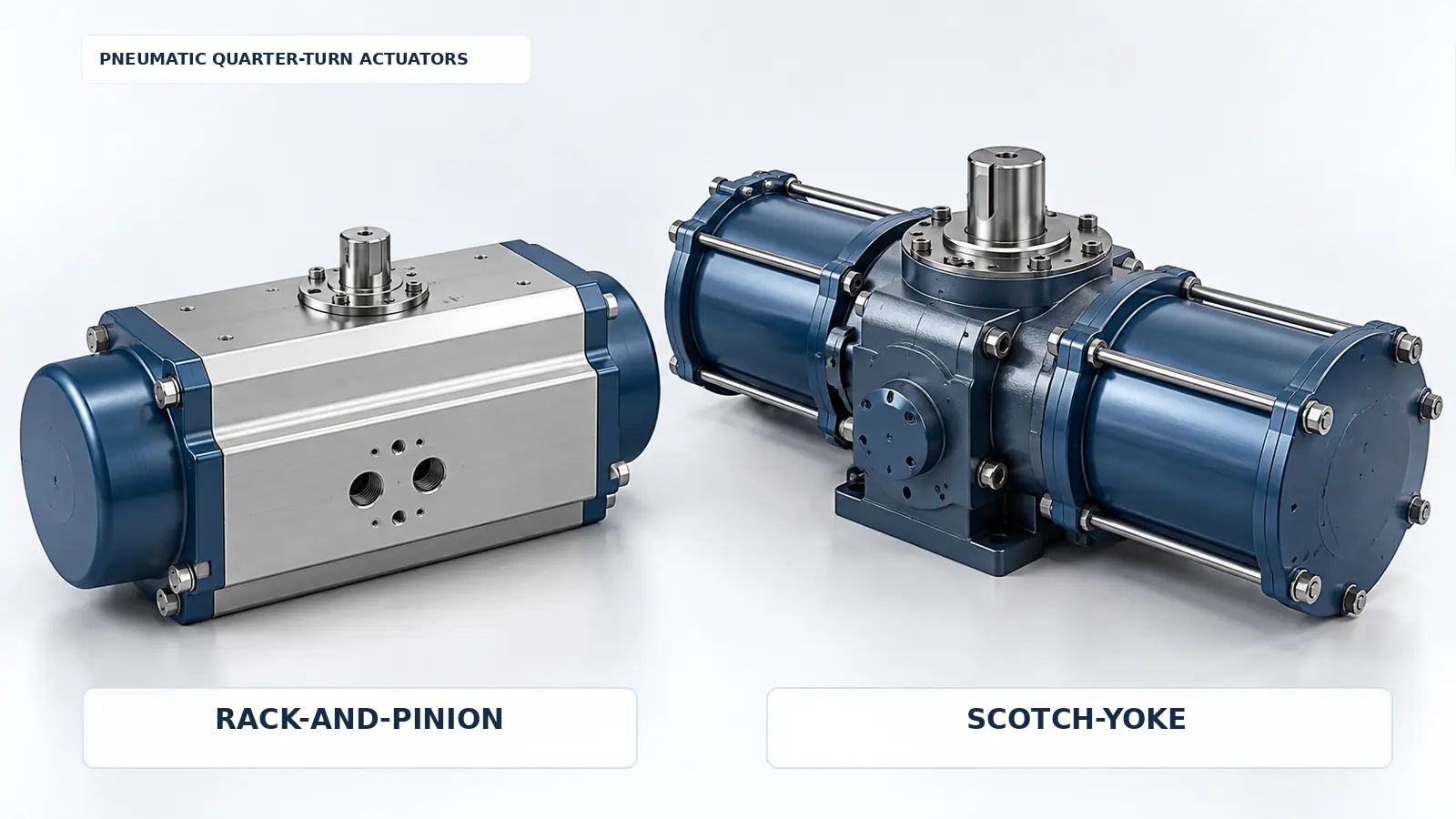
1. Rack-and-Pinion vs Scotch-Yoke: Key Differences at a Glance
Both designs convert linear piston motion into part-turn output, but their changing mechanical advantage is different. That affects the relationship between pneumatic input and output torque as the valve travels.
On smaller screens, scroll the table horizontally to see all columns.
| Fator de seleção | Rack-and-pinion actuator | Scotch-yoke actuator |
|---|---|---|
| Motion conversion | Linear rack engages an output pinion | Piston drives a slotted yoke or equivalent mechanism |
| Double-acting torque profile | Comparatively uniform in common designs | Non-linear; dependent on yoke geometry |
| Endpoint torque | No inherent pronounced endpoint peak in a conventional configuration | Mechanical advantage may be concentrated at one or both endpoints |
| Spring-return option | Available | Available |
| Valve applications | Ball, butterfly and plug valves | Ball, butterfly and plug valves |
| Critical matching evidence | Output table at applicable pressure and stroke positions | Exact-model output curve, geometry and movement direction |
| Erro comum | Treating advertised torque as constant for all configurations | Approving peak torque without checking lower-output positions |
A rack-and-pinion actuator can be suitable for a valve with substantial seating torque, and a scotch-yoke actuator can be suitable for a more uniform load. The deciding factor is the correspondence between available output and the valve’s required load at each critical travel position, not the mechanism name.
2. How Do Rack-and-Pinion and Scotch-Yoke Actuators Work?
Rack-and-Pinion: Piston, Rack and Output Pinion
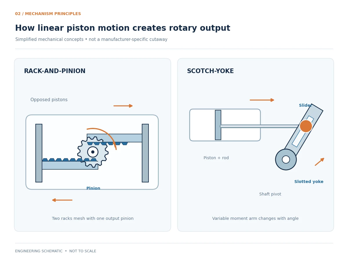
A conventional rack-and-pinion pneumatic actuator uses compressed air to move pistons coupled to linear gear racks. As the racks move, their teeth engage an output pinion and rotate the shaft. In common opposed-piston designs, racks engage the central pinion from opposite sides. Emerson’s rack-and-pinion mechanism reference explains the opposed-piston configuration used in common quarter-turn designs.
Because the effective pinion pitch radius is essentially fixed, theoretical output is relatively uniform when piston force is constant. Actual output also reflects friction, seal behavior, pressure, spring forces where installed, and the manufacturer’s design. Double-acting versions use pneumatic pressure for both movement directions; spring-return versions use stored spring energy for one direction.
Scotch-Yoke: Changing Mechanical Advantage
A scotch-yoke actuator uses a piston-driven member and a yoke to convert linear motion into rotation. The effective moment arm changes as the mechanism moves. Consequently, identical piston force does not produce identical torque at every output-shaft angle.
The exact distribution differs by yoke geometry. A symmetric yoke may favor both stroke endpoints; a canted yoke can shift mechanical advantage toward a selected endpoint. The manufacturer must identify the geometry, orientation and operating direction applicable to the quoted model.
Mechanism Type Does Not Define Failure Position
Rack-and-pinion and scotch-yoke describe mechanical conversion, not whether the installed valve fails open or closed. Failure response depends on spring configuration, valve orientation, air circuit, solenoid and control logic, and the named failure condition.
3. Torque Curve Comparison: Why Output Changes Across the Stroke
A torque curve relates actuator output to shaft position at specified operating conditions. It is useful only when supply pressure, travel direction, spring configuration and the manufacturer’s start/end conventions are clearly identified.
Rack-and-Pinion Torque Characteristics
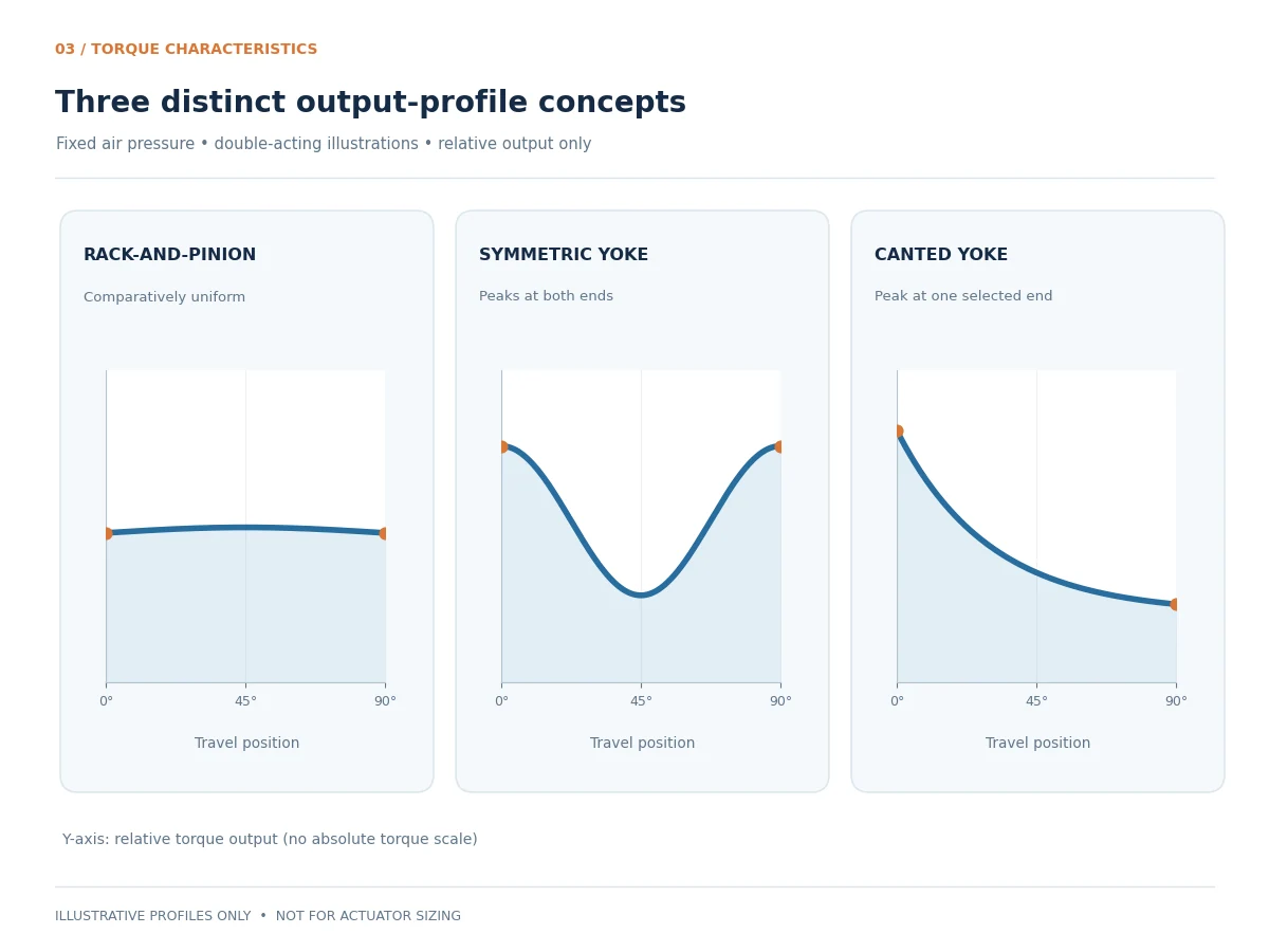
In a common double-acting rack-and-pinion design, the gear’s effective radius is relatively constant. At a fixed supply pressure, the theoretical torque profile is therefore comparatively flat. That does not mean the delivered output is perfectly constant or identical between models. Published values include design-specific friction and efficiency effects.
Adding return springs changes the output because spring force varies as the springs are compressed or released. An air-stroke value must not be used as a substitute for a spring-stroke value.
Symmetric Scotch-Yoke Torque Curve
A symmetric geometry can provide stronger mechanical advantage near both ends of travel and lower output in part of the middle range. This may match a valve with high breakaway and reseating loads, but the minimum intermediate output remains important if running or dynamic torque is substantial.
Canted Scotch-Yoke Torque Curve
Canted geometry can bias available torque toward one endpoint instead of providing a similar pair of endpoint peaks. Whether that feature is useful depends on the physical valve position and movement direction associated with the high-torque end. Rotork GP/GH technical information distinguishes symmetric and canted yoke torque characteristics; it does not establish performance for an unrelated actuator model.
Do Not Select from Peak Torque Alone
Two designs may advertise high peak torque at different shaft angles. An actuator with an impressive endpoint value may still be inadequate where the valve experiences its highest running load. The selection must therefore check the corresponding torque at each governing point and, where provided, the full output and demand curves.
How to Read a Supplier Torque Table Before Comparing Bids
Normalize these five fields before comparing two actuator offers: (1) shaft-angle reference, including whether 0° means valve closed or open; (2) air-driven versus spring-driven travel and clockwise/counterclockwise direction; (3) actual output at the specified mínimo supply pressure; (4) the exact model, spring set and yoke orientation; and (5) whether the figures represent start, end, minimum-in-stroke or peak torque. Data based on different reference conditions are not directly comparable.
Typical RFQ issue — mismatched shaft angles: One bidder identifies “start torque” at the beginning of an air stroke; another quotes “spring start” at the opposite physical valve position. Directly comparing those values can favor the wrong offer. Require both bids to identify valve closed/open positions, opening/closing directions and the same minimum air-pressure basis before reviewing torque adequacy.
Request the manufacturer’s curve or additional intermediate-position data where a start/end table cannot establish the governing mid-stroke requirement. If the supplier cannot document the relevant minimum, keep the actuator match open rather than interpolating an unsupported value.
4. Valve Matching: Ball, Butterfly and Plug Valves
Actuator selection begins with valve construction and operating duty. Valve size or pressure class alone cannot establish the required torque. The valve manufacturer should supply opening and closing load data for the governing operating differential pressure, temperature, seat condition and service. Confirm whether published values include factory allowances, breakaway after prolonged idle periods, and any direction-dependent or process-generated torque; do not apply an additional factor without first understanding the basis of the valve data.
Ball Valves: Breakaway, Running and Seating Loads
Válvulas esfera can require high torque to initiate movement from a seated position and different torque as the ball moves and reseats. Floating and trunnion-mounted designs, soft and metal seats, and special service conditions can change those loads. A scotch-yoke actuator may be useful where its high-output region matches the demand, but a suitably sized rack-and-pinion unit may also meet it.
For broader construction variables, refer to Raymon Valve’s Guia de seleção de válvulas esfera and use the specified valve manufacturer’s datasheet for the actual torque requirements.
Butterfly Valves: Disc Angle and Differential Pressure
Butterfly valve torque may include seating and bearing friction, pressure loading, and hydrodynamic effects. These contributions can change substantially with disc angle and service conditions. A design selected for strong endpoint torque may still be inadequate when the governing load occurs away from the endpoints. Check the exact válvula borboleta model and its specified operating cases.
Selection scenario — mid-stroke demand controls: A quarter-turn butterfly valve may have a critical hydrodynamic load away from its seat. A scotch-yoke option with high published endpoint torque can still be inadequate at that disc angle if its intermediate output is lower. Compare the valve OEM’s angle-dependent torque data with the exact actuator curve in both relevant directions; request missing intermediate data rather than extrapolating endpoint ratings.
Plug Valves: Friction and Service Conditions
Lubricated and sleeved plug valves may have different sealing-interface and friction characteristics. Pressure differential, lubrication, sleeve condition, temperature and operating frequency can affect breakaway and running loads. Do not transfer published torque figures between constructions without manufacturer approval.
Valve Torque Matching Matrix
On smaller screens, scroll the table horizontally to see all columns.
| Valve load point | Valve data required | Corresponding actuator check |
|---|---|---|
| Break-to-open | Required initial opening torque | Available opening-start torque |
| Run-to-open | Opening torque across travel | Available output throughout opening travel |
| End-to-open | Load near full-open position | Available opening-end torque |
| Break-to-close | Required initial closing torque | Available closing-start torque |
| Run-to-close | Closing torque across travel | Available output throughout closing travel |
| End-to-close | Final seating or closure torque | Available closing-end torque |
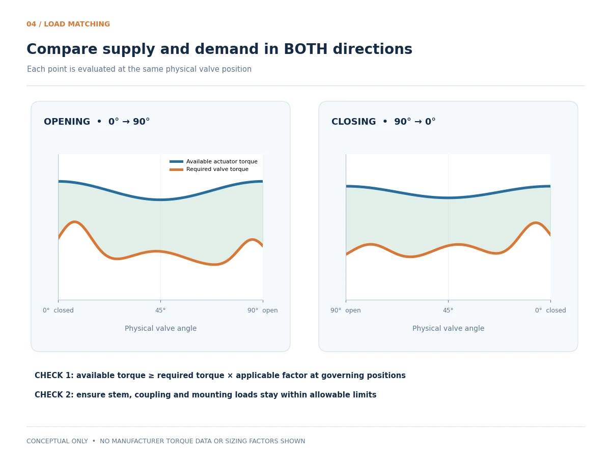
These are functional load positions. Air-start, air-end, spring-start and spring-end may refer to different physical valve angles. Match every supplier table entry to the actual opening or closing direction before comparing values.
Torque Margin and Mechanical Overload
A responsible sizing review addresses two separate boundaries. The selected actuator must produce sufficient output to overcome the governing valve demand, while the maximum delivered or potentially transmitted torque must remain within the applicable valve stem, coupling, bracket and other component limits.
Separate adequacy from overload: The actuator must meet the valve load at the governing operating point, but maximum deliverable torque at the highest credible pneumatic pressure also requires review against the allowable stem and coupling limits. A nominal mounting-flange size does not establish either torque adequacy or the mechanical strength of a separate bracket.
The factor must come from the approved project criteria and manufacturer’s data, accounting for allowances already incorporated in the published valve torque. No universal percentage is appropriate for all applications. Evaluate maximum mechanical load separately: an oversized actuator is not automatically a safer choice.
Worked Screening Logic: Why the Highest Peak May Lose
Consider a quarter-turn ball valve with a high opening breakaway load, lower running load and a separate end-to-close seating requirement. A proposed scotch-yoke actuator might provide ample opening-start torque but insufficient output at an intermediate position under minimum supply pressure. That candidate must not be approved merely because its peak is high. Another rack-and-pinion candidate with a lower advertised peak could remain viable if its documented output covers all applicable opening and closing points and respects mechanical limits. The opposite outcome is equally possible when a suitable scotch-yoke profile better matches the load.
Decision: Evaluate each candidate against the same approved valve load case and each applicable direction. This is a qualitative example, not a calculated actuator size or a substitute for the manufacturer’s torque matching worksheet.
5. Spring Return vs Double Acting: How Does the Torque Profile Change?
Double-Acting Output in Both Directions
A double-acting actuator uses pneumatic pressure to drive opening and closing. The actual torque for each direction depends on mechanism, air supply and losses. Use the specified minimum available pressure—not merely nominal plant-air pressure—for the governing movement.
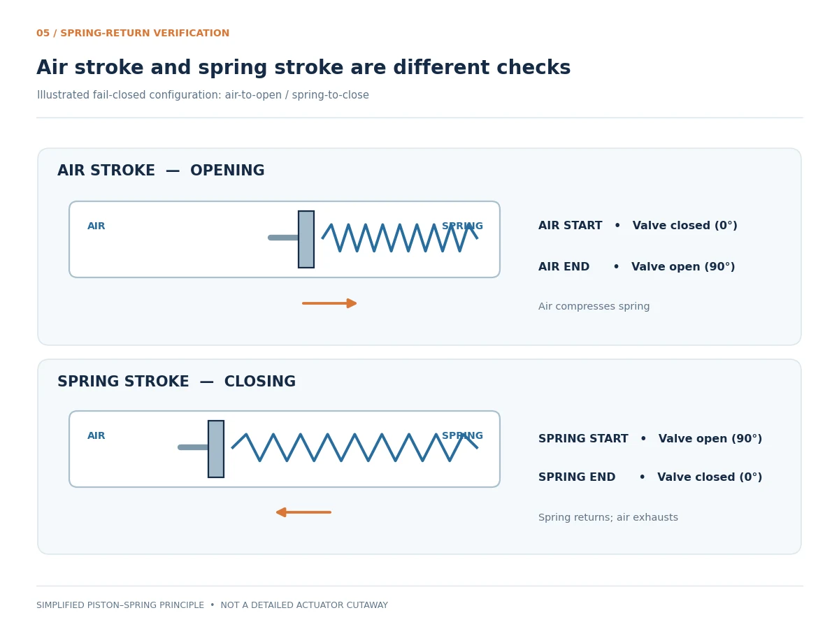
Air Stroke: Output While Compressing Springs
On the air-driven stroke of a spring-return actuator, some pneumatic force opposes the increasing spring force. Consequently, useful output at the shaft changes through travel. In a rack-and-pinion model this commonly reduces air-stroke torque as the springs compress; in a scotch-yoke model the mechanical advantage also changes.
Spring Stroke: Return After Air Depressurization
For the required spring-driven return, available torque reflects stored spring energy, varying spring force, mechanism geometry and losses. Check that spring output covers valve demand throughout return, and confirm that the pneumatic circuit permits required venting. Trapped air, exhaust restrictions or unsuitable controls may change the response.
On smaller screens, scroll the table horizontally to see all columns.
| Verification point | Governing load | Evidência do fornecedor |
|---|---|---|
| Air-stroke start | Valve load at start of the air-driven movement | Actuator air-start output |
| Air-stroke intermediate | Valve demand throughout travel | Air-stroke curve or documented intermediate output |
| Air-stroke end | Valve load at end of the air-driven movement | Actuator air-end output |
| Spring-stroke start | Valve load at start of spring return | Actuator spring-start output |
| Spring-stroke intermediate | Valve demand throughout return | Spring-stroke curve or documented intermediate output |
| Spring-stroke end | Valve load at final spring-return position | Actuator spring-end output |
Direction warning: In a fail-closed, air-to-open example, Air Start is at valve closed and Spring Start is at valve open. These start values cannot be compared as though they represent the same physical position.
Spring-return RFQ scenario: A quoted spring-end torque may satisfy the final seating load yet provide too little torque earlier in the return stroke, especially if the supplier supplies only start/end values. Ask for the manufacturer’s relevant minimum or intermediate spring-stroke output and confirm the exhaust route permits the intended fail movement under the specified loss-of-air scenario.
Fail-Closed, Fail-Open and Defined Failure Scenarios
The specified failure behavior must identify the triggering event: loss of instrument air, solenoid power, control signal or an emergency shutdown command. Spring return alone does not prove the complete valve package responds correctly to every failure. For a safety instrumented application, review the full safety function, required response time, pneumatic accessories and project evidence; do not infer SIL capability from a mechanical actuator description.
For shutdown duties, the functional test plan should define the initiating signal or failure, air and electrical starting conditions, required valve end position, permissible stroke time and observed response. A bench movement at nominal air pressure does not, by itself, prove the assembled valve will complete the required action at its maximum specified operating load.
On smaller screens, scroll the table horizontally to see all columns.
| Named scenario | What must be verified | Evidências a solicitar |
|---|---|---|
| Instrument-air supply lost | Required chamber venting, spring-driven direction, available spring torque and final valve position | Pneumatic schematic and spring-stroke torque table |
| Solenoid electrical power lost | Solenoid de-energized state and resulting air/exhaust routing | Solenoid specification, wiring/air circuit and functional test |
| Control signal lost | Positioner/logic behavior; do not assume it is identical to air failure | Control narrative, positioner configuration and loop test scope |
| Emergency shutdown demand | Command path, required valve position and maximum permitted response time | Cause-and-effect requirement and package-level acceptance procedure |
These are distinct verification scenarios. A spring-return label alone cannot demonstrate the response to a de-energized solenoid, failed positioner or shutdown command. Testing must use the failure scenarios specified in the project documents.
Worst-Case Operating Conditions
Review minimum available actuator supply pressure, applicable pressure losses, governing valve differential pressure, seat and temperature condition, stroke-time requirements and expected cycling. The limiting case may differ between opening, closing and the independent spring-return stroke; do not collapse them into one unspecified “worst case.” The selected package must satisfy every required operating and failure case under the approved combinations of conditions.
6. How to Select Between Rack-and-Pinion and Scotch-Yoke Actuators
When Rack-and-Pinion Is Worth Evaluating
Consider a rack-and-pinion actuator when its documented torque output matches the demand and the project favors its package envelope, mounting, duty requirements and supply scope. The mechanism is commonly evaluated for standard quarter-turn automation, but these are screening considerations rather than a universal suitability claim.
When Scotch-Yoke Is Worth Evaluating
Consider scotch-yoke when the required load is concentrated near a stroke endpoint or when a particular yoke geometry improves curve matching. Confirm whether the proposed symmetric or canted layout places the higher output where the valve actually needs it. Large nominal valve size is not, by itself, a selection rule.
On smaller screens, scroll the table horizontally to see all columns.
| Application condition | Preliminary screening direction | Required verification |
|---|---|---|
| Relatively uniform load | Evaluate rack-and-pinion | Torque in both directions across travel |
| High demand near both endpoints | Evaluate symmetric scotch-yoke | Minimum available torque in intermediate travel |
| High demand at a particular endpoint | Evaluate suitable canted scotch-yoke | Yoke orientation, high-torque position and rotation direction |
| Spring-return operation | Either mechanism may qualify | Both air and spring strokes at applicable conditions |
| Restricted space | Compare complete packages | Dimensions, installation orientation and access |
| Frequent modulating duty | Compare duty-rated configurations | Positioning behavior, cycle rating and maintenance |
| Large quarter-turn valve | Compare qualified actuator ranges | Actual valve torque and maximum mechanical loads |
Preliminary screening only. Final model and spring-set selection require approved valve torque data and exact-model manufacturer output information.
Selection Beyond Torque
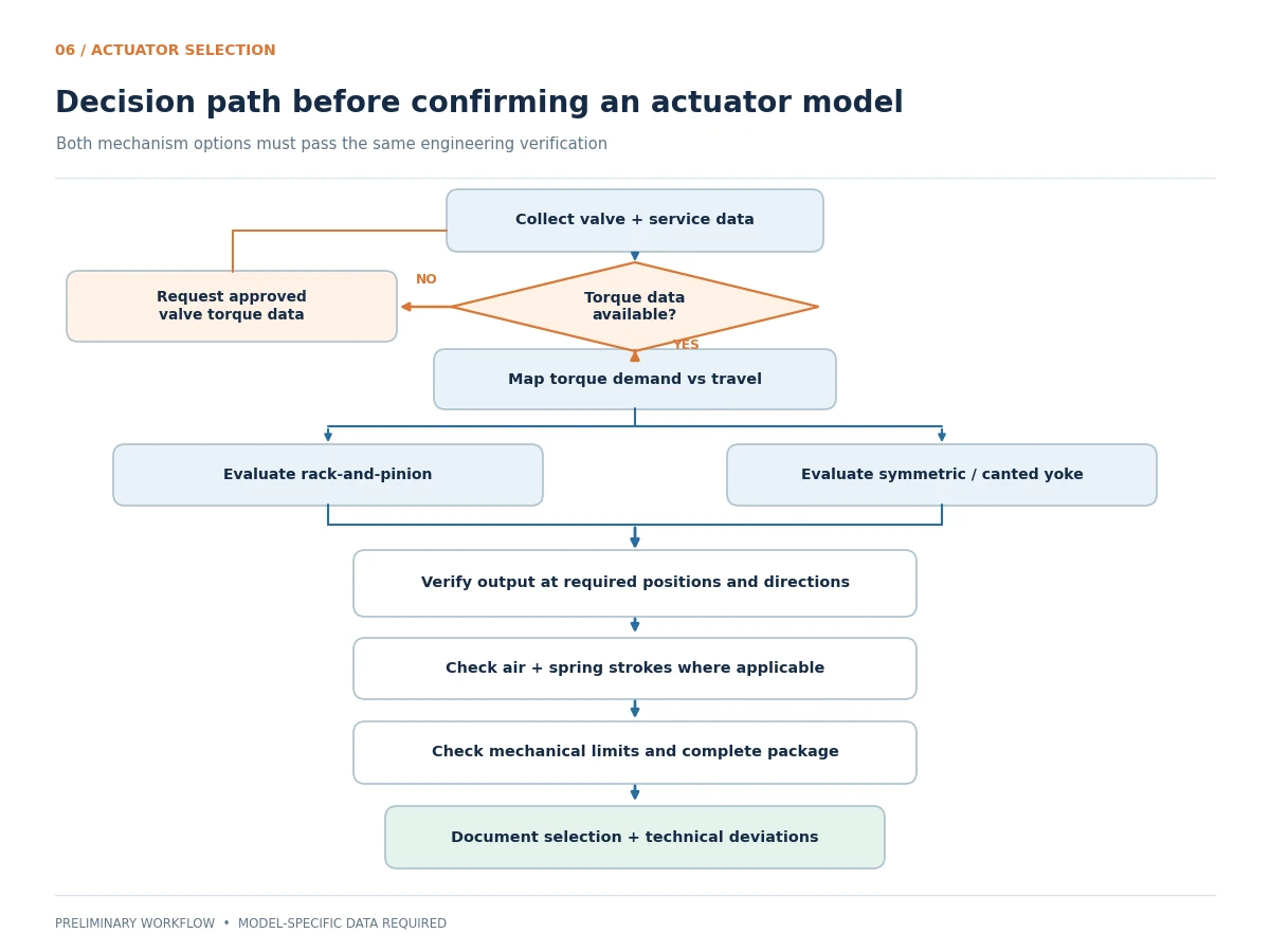
Once torque adequacy is established, evaluate cycle frequency, on/off versus modulating duty, travel time, compressed-air capacity, control accessories, corrosion exposure, ambient conditions, mounting interfaces, footprint and maintenance access. Compare complete actuation packages, not actuator housings alone.
A pneumatic-versus-electric comparison addresses the choice of energy source; this article instead compares two pneumatic motion-conversion mechanisms.
7. Pneumatic Actuator RFQ Checklist and Supplier Evaluation
Valve and Service Data to Submit
- Valve tag number, type, construction, size and service function
- Medium, temperature, required operating differential pressure and governing cases
- Opening and closing torque requirements across travel
- Maximum allowable valve stem, gearbox and coupling torque where applicable
- Operating frequency, on/off or modulating duty, and required rotation angle
Actuator, Air System and Failure Action
- Permitted rack-and-pinion or scotch-yoke mechanism, if the project specifies one
- Double-acting or spring-return configuration and requested spring direction
- Minimum and maximum instrument-air pressure, air quality and accessories
- Required fail-open, fail-closed or other response with exact failure scenarios
- Required opening and closing times and control/feedback scope
- Mounting orientation, coupling, environmental and hazardous-area requirements
What If the Valve Torque Data Are Missing?
Do not convert a valve size, pressure class or generic valve type into a final actuator model. Ask the valve OEM for direction-specific breakaway, running, seating and maximum allowable stem/coupling torque at the governing operating conditions. If only estimated data are initially available, record the assumptions and mark the actuator offer provisional — torque confirmation required. A final purchase approval should not depend on an unverified generic safety factor or a single catalog torque rating.
Supporting Documents and Inspection
Ask suppliers for the exact actuator model and spring set, model-specific air and spring output data, the documented torque matching assessment, assembly drawings, pneumatic schematic, accessories list, operation and maintenance instructions, agreed functional testing and a technical deviation register.
Where part-turn attachment requirements apply, ISO 5211:2026 specifies actuator attachment flange dimensions, driving-component dimensions and interface/coupling torque reference values. Attachment of an intermediate support to the valve is outside its stated scope, while use for control-valve attachments is subject to supplier–purchaser agreement. The standard does not establish that the selected actuator can operate the actual valve under its process conditions, or that the complete mounted package meets an operating or safety function. Confirm the contractually applicable edition and interface drawings. The standard explicitly leaves the intermediate support-to-valve attachment outside its scope; bracket, couplings and assembled load path therefore require separate project-specific review.
Supplier Technical Evaluation Matrix
On smaller screens, scroll the table horizontally to see all columns.
| Technical review item | Supplier evidence requested | Questão de aprovação |
|---|---|---|
| Valve torque | Approved opening and closing torque data | Are governing pressure, temperature and seat cases covered? |
| Saída do atuador | Exact-model torque table or curve | Is output adequate at corresponding angles and directions? |
| Spring return | Air and spring stroke data | Are both required strokes adequate? |
| Minimum air pressure | Output at specified minimum pressure | Does the package operate under the governing supply condition? |
| Mechanical overload | Stem, coupling and bracket allowable loads | Can unacceptable transmitted loads be avoided? |
| Failure action | Pneumatic schematic and functional specification | Is the defined response supported for each named failure? |
| Mounting | Approved assembly and interface drawing | Are attachment, travel and load limits suitable? |
| Functional testing | Test procedure, conditions and acceptance criteria | Can the specified assembled-package performance be demonstrated? |
| Desvios técnicos | Deviation register and documentation list | Have all exceptions been identified and approved? |
A lower-priced quotation should remain technically open if the underlying torque calculations, spring-return evidence, mounting or failure-action verification are missing. Technical assumptions and exceptions should be documented before purchase approval.
Normalize the Quotation Basis Before Commercial Comparison
Request each bidder to identify the same valve tag, process load case, actuator model and spring set, minimum air-pressure basis, spring/air direction mapping, torque margin convention, mounting accessories, controls, operating-time basis and included tests. Ask for a separate technical deviation register rather than allowing exclusions to remain buried in catalog notes. When comparing quotations, record each item as Compliant, Deviation for approval ou Missing evidence; a missing torque match is not a minor commercial exception.
Quotation-comparison scenario: A lower-priced pneumatic package may omit the coupling or bracket, solenoid valve, limit switches, local indication or functional acceptance test included in a competing offer. Normalize supply scope, exclusions, delivery documents and test responsibilities on the same valve-tag basis before treating the difference as a cost saving. Record unresolved technical deviations separately from commercial negotiations.
8. Frequently Asked Questions
What is the main difference between rack-and-pinion and scotch-yoke pneumatic actuators?
The motion-conversion mechanism and torque distribution differ. Rack-and-pinion actuators commonly have a comparatively uniform double-acting output, while scotch-yoke designs provide a geometry-dependent, non-linear profile.
Which actuator provides higher torque at the beginning and end of the stroke?
No mechanism is universally higher in absolute torque. A symmetric scotch-yoke can emphasize both endpoints; a canted design may emphasize one. Compare the actual output values at the relevant air pressure and positions.
Is a scotch-yoke actuator better for large ball valves?
Not automatically. Its torque distribution can be beneficial when matched to the valve demand, but a suitably rated rack-and-pinion actuator may also qualify. Valve torque data and mechanical limits govern.
Can both rack-and-pinion and scotch-yoke actuators use spring return?
Yes. Both can be configured for spring return. The air and spring strokes must be checked separately for required torque, the specified failure action and the complete pneumatic circuit.
How do you match pneumatic actuator torque to valve torque requirements?
Compare available actuator torque against the required valve torque at corresponding positions and movement directions, at governing air and process conditions. Also verify applicable sizing factors and maximum allowable mechanical loads.
What information is needed to select a pneumatic actuator for an industrial valve?
Provide the valve datasheet, opening and closing torque profiles, allowable mechanical loads, operating differential pressure, minimum air pressure, required stroke time, failure action, mounting details and control accessories.
9. Final Selection Recommendation
Neither rack-and-pinion nor scotch-yoke should be chosen simply because it is perceived as stronger. Rack-and-pinion arrangements can produce relatively uniform double-acting output; scotch-yoke arrangements can redistribute mechanical advantage toward critical travel positions. The correct actuator is the one whose documented available output satisfies the specified valve demand in every governing direction and position, while respecting mechanical limits and complete-package requirements.
Request Actuator Torque Review
Submit your valve datasheet, operating differential pressure, opening and closing torque data, minimum available instrument-air pressure, required fail position, stroke time and mounting requirements for a project-specific actuator matching review.
Submit Your Valve Datasheet →Engineering limitations: This comparison is for screening and RFQ preparation, not final sizing or certification. Approve the package only against the project specification, model-specific torque data, interface load limits and supplier documentation.
Engineering source notes: Manufacturer descriptions of motion-conversion mechanisms and yoke geometry are cited in the relevant sections; the ISO 5211:2026 scope is linked alongside the mounting discussion. OEM torque output tables and exact project specifications remain the governing evidence for approval.
Related technical resources: Centro de Conhecimento Raymon Valve · Sobre a Raymon Valve.
 Portuguese
 English
 German
 Arabic
 French
 Spanish
 Italian
 Russian