
Specify pneumatic valve actuator accessories as one coordinated package—not as a standard shopping list. Start with the valve operating duty, actuator action, required response to each failure event, instrument-air conditions, control signals, mounting interfaces and acceptance tests. A positioner, solenoid valve, air filter regulator, limit switch box and air lock relay perform different functions; the correct combination depends on whether the valve is on/off, modulating or required to hold or move to a defined position after a fault. This guide turns those inputs into a practical RFQ and package-verification checklist.
A coordinated specification helps prevent incompatible connections, inadequate air-flow capacity, incorrect feedback and unexpected valve movement during a failure. For wider product context, review Raymon Valve’s gama de produtos de válvulas industriais.

In This Guide
- Quick decision path
- Why specify the complete package
- Define the actuator duty
- Specify a positioner
- Specify a solenoid valve
- Specify an air filter regulator
- Specify limit switches
- Specify an air lock relay
- Select accessories by application
- Compare accessory specification inputs
- Failure modes and verification
- Evaluate the supplier’s technical offer
- Package FAT and documentation
- Common specification mistakes
- Prepare the RFQ
- Perguntas frequentes
Quick Decision Path: Define the Automation Duty Before Choosing Accessories
Use the required valve behavior to establish the accessory scope. This table is a preliminary configuration aid; the approved cause-and-effect chart and pneumatic schematic govern the final arrangement.
| Required duty | Define first | Accessory functions to evaluate | Não assuma |
|---|---|---|---|
| On/off operation | Actuator action, command source, energized/de-energized state and end-position feedback | Solenoid switching, AFR where required, open/closed limit indication | A positioner is automatically required |
| Modulating control | Control signal, required travel, feedback, air supply and response requirements | Positioner, AFR, optional transmitter and any separately specified trip solenoid | A trip solenoid can be added without checking its interaction with the positioner circuit |
| Fail-open / fail-close | Required final valve position after each defined failure event | Spring-return actuator or engineered stored-energy arrangement; coordinated solenoid and trip logic | Solenoid NC/NO designation alone defines the complete assembly’s fail action |
| Fail-last | Which failure is covered, which actuator chambers must be isolated, and the required holding period | Lock-up arrangement, leakage control and possibly a separately sized air receiver | An air lock relay guarantees indefinite position retention |
Specify failure events separately. Electrical power failure, instrument-air supply failure, loss of control signal and an emergency shutdown command are different events. State the required actuator response for each event in the control philosophy and verify the complete circuit against it.
1. Why Pneumatic Actuator Accessories Must Be Specified as a Complete Package
A pneumatic valve actuator converts compressed air energy into mechanical movement to operate an industrial valve. Its accessories provide control, positioning, air preparation, position indication and additional pneumatic functions.
The accessory arrangement depends on whether the valve is designed for on/off operation, modulating control or a specific failure response.
| Accessory | Main function | Aplicação típica |
|---|---|---|
| Valve positioner | Controls actuator position according to a command signal | Modulating control |
| Válvula solenoide | Switches pneumatic flow using an electrical command | On/off control and shutdown |
| Air filter regulator (AFR) | Filters and regulates instrument air | Pneumatic supply conditioning |
| Caixa de fim de curso | Provides discrete valve position signals | Open/closed feedback |
| Air lock relay | Traps actuator air under specified low-supply-pressure conditions | Fail-last applications |
A complete valve package may also include an air receiver, volume booster, quick exhaust valve, pressure gauges, pneumatic tubing and fittings. These additional components should be considered when the required actuator operating time, air consumption or failure response cannot be achieved with a basic accessory arrangement.
2. Identify the Required Pneumatic Actuator Configuration Before Selecting Accessories
The first step is to define the operating philosophy rather than simply selecting accessories from a standard list.
2.1 On/Off Pneumatic Actuator Configuration
On/off actuators move a valve between two defined positions, normally fully open and fully closed.
Double-acting actuator: Compressed air drives the actuator in both directions. A pneumatic directional control arrangement is required. A solenoid valve may switch the air supply, while limit switches may provide open and closed feedback.
Spring-return actuator: Compressed air drives the actuator against a mechanical spring. Loss of the relevant pneumatic supply allows the spring to move the actuator toward its designed failure position. The required fail-open or fail-close direction must be confirmed.
The solenoid valve arrangement must be coordinated with the actuator’s pneumatic circuit. Selecting a solenoid based only on the number of ports or coil voltage is insufficient.
2.2 Modulating Pneumatic Actuator Configuration
Modulating service requires the actuator to move to intermediate positions according to a control command. A typical configuration includes a pneumatic actuator, electro-pneumatic positioner, air filter regulator, position feedback where required, and a solenoid valve if a separate shutdown or trip function is specified.
The positioner receives a control signal and adjusts pneumatic output pressure to achieve the commanded valve position. A common electrical control signal is 4–20 mA, but the actual input range and communication protocol must be specified by the project.

2.3 Fail-Open, Fail-Close and Fail-Last Configurations
The required failure response must be defined before accessory selection.
| Failure response | Expected valve behavior | Main design consideration |
|---|---|---|
| Fail-open | Moves toward open position | Actuator spring direction or engineered backup arrangement |
| Fail-close | Moves toward closed position | Actuator spring direction or engineered backup arrangement |
| Fail-last | Attempts to retain its existing position | Suitable pneumatic locking arrangement and leakage control |

Fail-last is not automatically provided by a double-acting actuator or by installing an ordinary solenoid valve. The complete pneumatic circuit must be reviewed, including the positioner, solenoid valve, air lock relay, actuator chambers and possible leakage paths.
2.4 Verify the Actuator and Mounting Interface Before Finalizing Accessories
Accessories cannot compensate for an actuator that is incorrectly sized or mechanically incompatible with the valve. Before approving the accessory list, confirm the valve torque requirement and the actuator’s available output across the full operating range.
| Retenção | Information to obtain | Por que é importante |
|---|---|---|
| Valve torque profile | Breakaway, running, seating and any relevant dynamic torque at the specified differential pressure and temperature | Actuator output must cover the actual operating duty, not only a nominal catalogue value |
| Saída do atuador | Output torque at minimum and maximum available air pressure; spring torque range for spring-return units | Confirms operation at the least favorable supply condition and avoids relying on maximum-pressure data alone |
| Mechanical limits | Valve stem/coupling maximum allowable torque and actuator output limits | Available actuator torque must not exceed the valve or coupling’s permitted limit |
| Air demand and speed | Actuator air consumption, required stroke time, supply pressure at the actuator and tubing/solenoid flow restrictions | Accessory flow capacity and air-system capacity affect actual travel time |
| Mounting kit | Flange interface, drive dimensions, coupling, bracket, alignment and fasteners | Prevents mechanical mismatch, side loading and incorrect feedback travel |
| Limites ambientais | Ambient temperature, corrosion exposure, vibration, enclosure and hazardous-area requirements | Applies to the actuator and every electrical/pneumatic accessory in the package |
For part-turn assemblies, confirm the valve-to-actuator attachment against the applicable interface standard and the exact valve and actuator drawings. ISO 5211:2026 specifies attachment dimensions and reference torque values for part-turn actuator interfaces; it does not replace the valve torque calculation, the valve or actuator manufacturer’s limits, or the purchaser’s control philosophy.
Do not apply a generic safety factor or assume a universal actuator torque margin. The sizing method, factor and acceptance criteria should come from the project specification and the responsible valve/actuator supplier.
Typical RFQ review scenario: A valve and actuator may share a nominal size and mounting pattern, yet the actuator can still be unsuitable at the minimum available air pressure or can exceed the valve stem or coupling torque limit at maximum pressure. Compare the valve torque profile at the specified differential pressure and temperature with actuator output across its pressure range. Record the sizing-margin basis and the maximum permitted output torque; do not use nominal valve size as a substitute for these checks.
3. How to Specify a Pneumatic Valve Positioner
A valve positioner controls actuator travel according to a control input. It compares the commanded position with the actual actuator or valve position and adjusts pneumatic output to reduce the difference.
Positioners are commonly used for continuous flow control, pressure regulation, temperature control, modulating process applications and applications requiring more precise position control than a basic pneumatic switching arrangement. A positioner is not automatically required for every pneumatic actuator.
3.1 Types of Positioners
- Pneumatic positioner: Receives a pneumatic control signal and regulates actuator output pressure.
- Electro-pneumatic positioner: Receives an electrical control signal and converts it into pneumatic output.
- Smart positioner: Uses electronic control and may provide diagnostic information, communication capabilities and configuration functions.
3.2 Positioner Specification Checklist
| Specification field | What the buyer should define |
|---|---|
| Positioner type | Pneumatic, electro-pneumatic or smart |
| Input signal | Required electrical or pneumatic signal |
| Comunicação | HART, fieldbus or other specified protocol |
| Actuator type | Linear or rotary |
| Actuator action | Single-acting or double-acting |
| Travel | Required stroke or rotation angle |
| Feedback | Required travel feedback arrangement |
| Air supply | Available supply pressure and air quality |
| Pneumatic output | Required output pressure and flow |
| Mounting | Direct mounting or bracket arrangement |
| Enclosure | Required IP protection |
| Área classificada | Applicable electrical certification |
| Diagnostics | Required monitoring and diagnostic functions |
| Acessórios | Gauges, feedback transmitter and communication options |
3.3 Positioner Mounting and Compatibility
Confirm the actuator-to-positioner interface drawing, bracket dimensions, feedback shaft or linkage, available travel, mounting orientation, mechanical clearance and the positioner manufacturer’s installation instructions. A nominal interface label alone does not establish full mechanical or pneumatic compatibility.
| Referência | Interface scope | Specification check |
|---|---|---|
| ISO 5211:2026 | Part-turn actuator attachment to an industrial valve | Confirm valve top flange, drive dimensions, coupling and permitted torque. |
| VDI/VDE 3845 Blatt 1 | Pneumatic part-turn actuator interfaces to auxiliary equipment, including positioners, signal transmitters and compressed-air connections | Confirm the actual actuator accessory mounting pattern, air ports, bolt layout and any adapter. |
| VDI/VDE 3847 Blatt 1 | Additional interface between a lifting control-valve actuator and its positioner | Confirm linear actuator / positioner interface and compatibility of the specified mounting arrangement. |
| VDI/VDE 3847 Blatt 2 | Additional interface between a rotary control-valve actuator and its positioner | Confirm rotary actuator / positioner interface, including any pilot-valve mounting arrangement. |
| IEC 60534-6-1 / IEC 60534-6-2 | Positioner mounting details for linear / rotary control-valve actuators | Check the project-adopted edition and the manufacturer’s mounting instructions. |
Do not use the word “NAMUR” as a substitute for an interface drawing. Confirm the actual bolt pattern, feedback shaft or linkage, pneumatic port arrangement, pilot-valve mounting and adapter requirements for the selected actuator and accessory models.
For related standards context, consult Raymon Valve’s valve standards resource.
Typical mounting review scenario: A positioner may appear to match the actuator’s bolt pattern, but the feedback shaft, lever travel, rotation direction or bracket geometry may prevent the positioner from tracking the full valve stroke. Check the model-specific mounting drawing and verify full travel and feedback direction during the agreed functional test.
4. How to Specify a Pneumatic Solenoid Valve
A solenoid valve uses an electrical signal to control pneumatic flow. In an automated valve package, it may supply compressed air to an actuator, switch pneumatic connections, initiate an actuator stroke, execute an electrical shutdown command or implement a defined de-energized pneumatic state.
The solenoid valve must be selected according to the actuator type and required pneumatic circuit.
4.1 Common Solenoid Valve Arrangements
| Arrangement | Uso típico | Important consideration |
|---|---|---|
| 3/2-way | Commonly used with single-acting actuators | Porting and spring-return circuit |
| 5/2-way | Commonly used with double-acting actuators | Directional switching |
| 5/3-way | Applications requiring an additional center position | Center condition and circuit design |
These are typical arrangements, not universal rules. The correct configuration depends on the actuator, control logic and specified failure response.
4.2 Normally Open vs Normally Closed Solenoid Valves
NO and NC describe the electrical de-energized state of the solenoid valve’s relevant ports. However, the terms alone do not establish whether the complete valve assembly will fail open or fail closed.
The buyer should specify the electrical state during normal operation and shutdown, pneumatic connections in energized and de-energized conditions, required actuator movement following each state, and whether a separate air supply failure response is required.
4.3 Solenoid Valve Specification Checklist
| Specification field | Informações necessárias |
|---|---|
| Função da válvula | Pneumatic switching or shutdown |
| Disposição do passe | 3/2, 5/2, 5/3 or specified alternative |
| Operating voltage | Actual AC or DC supply |
| Frequência | Required AC frequency, where applicable |
| Power consumption | Maximum permitted coil power |
| Pressure range | Minimum and maximum operating pressure |
| Capacidade de fluxo | Required actuator operating time |
| Material do corpo | Project material requirement |
| Coil protection | Enclosure and environmental protection |
| Área classificada | Required certification and protection concept |
| Comando manual | Required, optional or prohibited |
| Electrical entry | Cable gland and connection arrangement |
| De-energized state | Defined port connections and actuator response |
| Actuator air volume / consumption | Manufacturer’s actuator volume or air consumption per stroke at the stated conditions |
| Required travel time | Required opening and closing time, stated separately where they differ |
| Rated solenoid flow | Manufacturer-rated flow or flow coefficient at stated inlet pressure, outlet pressure and reference conditions |
| Tubing and fittings | Tubing inside diameter, approximate length, fittings, manifolds and other restrictions |
| Exhaust restrictions | Silencer / exhaust arrangement and any permitted back-pressure |
| Pilot pressure range | Minimum and maximum pilot / operating pressure for the selected solenoid version |
| 5/3 center condition | Closed center, exhaust center, pressure center or another explicitly defined arrangement |
A 5/3 solenoid valve must be specified by its required center condition as well as its port arrangement. A closed-center spool position does not, by itself, guarantee a leak-tight or safety-rated fail-last function. Verify internal leakage, actuator chamber connections and the complete circuit against the required failure response.
The RFQ should request a pneumatic circuit diagram showing the solenoid valve’s actual connections. For shutdown applications, the electrical and pneumatic failure logic should be reviewed as part of the complete safety function rather than inferred from the solenoid valve specification alone.
Typical flow-capacity review scenario: A solenoid coil voltage and port size may match the datasheet, yet the valve actuator still misses its required stroke time. The cause may be inadequate rated flow at the actual pressure conditions, a restrictive filter regulator, small or long tubing, restrictive fittings or exhaust back-pressure. Check actuator air consumption, minimum package supply pressure, solenoid and regulator flow data, tubing dimensions and exhaust arrangement together; verify the result at the specified minimum supply condition.
5. How to Specify an Air Filter Regulator (AFR)
An air filter regulator combines two functions: removing specified contaminants from compressed air and regulating the downstream air pressure supplied to pneumatic equipment. Clean and properly regulated air helps maintain reliable operation of positioners, solenoid valves and pneumatic actuators.
5.1 Filter Regulator Specification Fields
| Specification field | What to define |
|---|---|
| Inlet pressure | Minimum, normal and maximum supply pressure |
| Outlet pressure | Required regulated pressure |
| Filtration rating | Required particle filtration performance |
| Capacidade de fluxo | Maximum expected air consumption |
| Drain type | Manual or automatic as specified |
| Relief function | Relieving or non-relieving arrangement |
| Bowl material | Environmental and corrosion suitability |
| Gauge | Required pressure indication |
| Setpoint security | Locking or adjustment protection |
| Conexões | Pneumatic port size and thread standard |
| Mounting | Orientation and installation arrangement |
5.2 Instrument Air Quality and Pressure Compatibility
Air quality should be specified according to the requirements of the pneumatic equipment and the project. ISO 8573-1 classifies compressed-air purity with respect to particles, water and oil; it does not prescribe one universal air-quality class for all pneumatic actuators.
The buyer should confirm required filtration performance, moisture and condensate conditions, oil contamination limits, available instrument air pressure, required regulated pressure and maximum air consumption during actuator operation.
A filter regulator should not be selected only by connection size. Its flow capacity must also be adequate for the actuator and associated pneumatic accessories. The regulated outlet pressure must remain within the permitted operating range of the positioner, solenoid valve and actuator.
The filter element’s nominal or absolute particle rating (for example, a stated micron rating) is not the same as an ISO 8573-1 compressed-air purity class. If the project specifies an ISO class, identify the required particle, water and total-oil classes at the relevant point of use and confirm that the complete air-treatment system can achieve them. A basic filter regulator should not be assumed to remove water vapour, oil vapour or all gaseous contaminants. Depending on the incoming air and the specified class, upstream drying, water separation, coalescing filtration or other treatment may be required.
At the time of this review, ISO 8573-1:2010 remains the published edition shown by ISO, while ISO/AWI 8573-1 Edition 4 is under development. Confirm the latest published edition and the purchaser’s required air class before procurement; do not infer a universal class from the AFR model alone.
6. How to Specify a Pneumatic Actuator Limit Switch Box
A limit switch box provides discrete electrical position signals. Typical applications include fully open indication, fully closed indication, remote valve position monitoring, PLC and DCS status feedback, and interlock or sequence monitoring.
A limit switch box does not normally provide continuous valve position feedback. If continuous position measurement is required, specify a suitable position transmitter or position feedback device.
6.1 Mechanical vs Proximity Switches
Mechanical switches use physical contact to change the electrical state when the actuator reaches a defined position. Proximity switches detect the position of a target without requiring the same mechanical contact arrangement. Common proximity technologies include magnetic and inductive types.
6.2 Limit Switch Specification Checklist
| Specification field | Informações necessárias |
|---|---|
| Number of switches | Required open/closed and additional signals |
| Switch technology | Mechanical, magnetic or inductive |
| Contact arrangement | NO, NC, SPDT or DPDT as applicable |
| Voltage rating | Actual circuit voltage |
| Current rating | Required switching current |
| Output type | Dry contact, PNP, NPN or specified interface |
| Switching points | Required open and closed indication positions |
| Enclosure | Required IP protection |
| Área classificada | Applicable certification |
| Cable entries | Quantity, size and thread |
| Terminal arrangement | Required terminal configuration |
| Mounting | Actuator interface and bracket |
The specification should also define the acceptable switching tolerance and how the indication points will be verified during testing. For installations in hazardous areas, the complete electrical equipment arrangement must satisfy the applicable project and jurisdictional requirements.
7. How to Specify an Air Lock Relay (Lockup Valve)
An air lock relay, also called a lockup valve, is used in pneumatic circuits where maintaining actuator position following a loss or reduction of instrument air is required. When the supply pressure falls below its specified operating threshold, the relay changes state to isolate or retain pneumatic pressure in the relevant actuator circuit.
Its purpose is to help maintain the existing actuator position rather than automatically drive the valve to an open or closed position. However, an air lock relay does not guarantee indefinite position retention. Leakage through actuator seals, tubing, fittings, valves or other circuit components can cause pressure loss and position drift.
7.1 Air Lock Relay Specification Fields
| Specification field | Informações necessárias |
|---|---|
| Aplicação | Fail-last requirement |
| Actuator type | Single-acting or double-acting |
| Pressão operacional | Normal supply pressure range |
| Lockup threshold | Specified low-pressure switching point |
| Pneumatic connections | Disposição do passe |
| Capacidade de fluxo | Required actuator operating performance |
| Holding requirement | Expected position-retention period |
| Requisito de estanqueidade | Permitted leakage or pressure decay |
| Reset behavior | Recovery after air supply restoration |
| Circuit compatibility | Positioner, solenoid and actuator arrangement |
7.2 Air Lock Relay vs Solenoid Valve vs Air Receiver
| Componente | Main purpose | Does it store additional compressed air? |
|---|---|---|
| Válvula solenoide | Electrically controlled pneumatic switching | No |
| Air lock relay | Isolates or retains actuator air under specified conditions | No independent reserve |
| Air receiver | Stores compressed air for specified backup requirements | Sim |
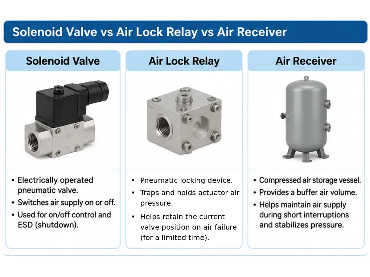
An air receiver can provide stored pneumatic energy for a defined operating requirement. An air lock relay is used to isolate or retain air already present in the actuator circuit. For double-acting actuators, the engineer must verify how both actuator chambers are isolated or controlled. A device that only interrupts the main supply may not provide the required fail-last behavior in every circuit configuration.
| Failure event / requirement | Typical device or circuit function | What must be confirmed |
|---|---|---|
| Loss of instrument-air supply / low supply pressure | A pneumatic lock-up valve may sense supply pressure falling below its setpoint and isolate or block actuator-side pneumatic pressure in the specified circuit. | Sensing point, setpoint, hysteresis, porting, actuator chamber isolation, leakage and position drift over the required holding period. |
| Loss of electrical power to a solenoid | The solenoid returns to its de-energized port state; actuator response depends on the selected valve function, spring action and circuit. | Coil de-energized port map, actual actuator movement, and whether a separate holding function is required. |
| Loss of 4–20 mA / control signal | A positioner or dedicated signal-monitoring / fail-in-place function may retain a last position if that function is provided and configured. | Exact positioner model, signal-loss behavior, pneumatic output behavior, parameter settings and manufacturer’s manual. |
| ESD / independent trip command | A dedicated trip solenoid or shutdown circuit changes pneumatic connections or vents / supplies the actuator as defined by the cause-and-effect design. | De-energized state, trip logic, required fail position, reset sequence and integrated functional test. |
| Need for one or more powered strokes after air failure | An air receiver provides stored compressed air for a defined backup duty; it does not itself create a fail-last function. | Usable pressure range, actuator air consumption, number of strokes, leakage, reserve and receiver sizing calculation. |
Manufacturer documentation illustrates that a pneumatic lock-up valve can isolate an actuator signal-pressure line when supply pressure falls below an adjusted value, while a positioner fail-in-place module may be a separate function for loss of electrical control signal. These are example architectures, not universal behavior: verify the exact model manual and the approved pneumatic schematic. The order of components in the circuit can also affect which device has priority.
7.3 Air Lock Relay Circuit and Holding Verification
For a fail-last requirement, review the complete pneumatic schematic rather than specifying the lock-up relay as a stand-alone item. The review should identify the relay’s sensing connection, supply and output ports, the actuator chamber connections, positioner outputs, solenoid valve porting, exhaust paths and any bypass or reset arrangement.
| Item de verificação | Question for the supplier / engineer | Evidence or test record |
|---|---|---|
| Failure coverage | Does the arrangement respond to loss of instrument air, low supply pressure, electrical power loss, or only a defined subset? | Cause-and-effect matrix and pneumatic schematic |
| Chamber isolation | For a double-acting actuator, are both chambers isolated or otherwise controlled as required? | Marked-up circuit drawing and functional test |
| Trip threshold | What low-pressure threshold triggers lock-up, and what hysteresis/reset behavior is specified? | Setpoint datasheet and calibrated test record |
| Position retention | What holding period and allowable position drift are required? | Time-based pressure-decay / position-drift test against purchaser-approved limits |
| Leakage paths | Have actuator seals, tubing, fittings, solenoid, positioner and lock-up device leakage paths been considered? | Leak test procedure and recorded results |
| Recovery | Does air restoration cause automatic resumption, require reset, or require a control-system command? | Approved recovery sequence and functional test |
Important for spring-return actuators: a lock-up device must not inadvertently defeat the spring’s intended fail-open or fail-close action. If fail-last is required, the supplier must show how that requirement is reconciled with the actuator construction and the specified failure cases.
Air receiver sizing is a separate calculation. If stored air is required to complete one or more strokes, the receiver volume and usable pressure range must be calculated from actuator air consumption, required strokes, minimum operating pressure, reserve margin, leakage allowance and system configuration. A lock-up relay does not provide this stored volume.
8. How to Select Accessories for Different Actuator Applications
| Aplicação | Posicionador | Válvula solenoide | AFR | Limit switch | Air lock relay |
|---|---|---|---|---|---|
| On/off double-acting ball valve | Usually not required | As specified | According to air system | As specified | Only for fail-last |
| On/off spring-return butterfly valve | Usually not required | As specified | According to air system | As specified | Only if required |
| Modulating control valve | Normally required | If trip/override is required | According to positioner requirements | Optional | If fail-last is specified |
| Fail-open assembly | Depends on duty | According to control philosophy | According to air system | As specified | Not a substitute for fail action |
| Fail-close assembly | Depends on duty | According to control philosophy | According to air system | As specified | Not a substitute for fail action |
| Fail-last assembly | Depends on duty | According to control philosophy | According to air system | As specified | Suitable locking arrangement required |
This is an initial configuration guide, not a universal accessory schedule. The final configuration depends on actuator design, valve operating duty, pneumatic circuit, control philosophy and project requirements.
8.1 Questions to Answer Before Approving the Configuration
- Is the valve intended for on/off or modulating operation?
- Is the actuator single-acting or double-acting?
- What should happen following electrical power failure?
- What should happen following instrument air failure?
- Is a separate shutdown command required?
- Is continuous position feedback necessary?
- Is discrete open/closed indication sufficient?
- Is fail-last operation required?
- Is backup stored air required?
- What operating time and testing criteria apply?
8.2 Other Accessories to Evaluate When the Application Requires Them
Depending on actuator volume, required stroke time, control accuracy, diagnostics and backup duty, the package may also require a volume booster, quick-exhaust valve, I/P converter, continuous position transmitter, air receiver or manual override. These are application-driven options, not standard additions. Confirm their function, sizing data, porting, mounting, failure behavior and interaction with the positioner and solenoid circuit before adding them to the purchase specification.
9. Pneumatic Actuator Accessory Specification Comparison Table
| Accessory | Critical specification inputs | Main compatibility check | Typical omission risk |
|---|---|---|---|
| Posicionador | Signal, action, travel, air supply | Actuator movement and mounting | Incorrect positioning |
| Válvula solenoide | Voltage, ports, pressure, flow | Actuator circuit and trip logic | Incorrect pneumatic switching |
| AFR | Filtration, pressure, flow | Instrument air and equipment limits | Unstable or contaminated air supply |
| Limit switch | Contacts, electrical rating, setting | PLC/DCS input and actuator travel | Incorrect position indication |
| Air lock relay | Lockup threshold, ports, leakage | Complete actuator pneumatic circuit | Failure to retain position |
A supplier should provide a coordinated accessory schedule rather than five unrelated product datasheets. The technical offer should identify deviations from the purchaser’s requirements, including changes to mounting arrangements, signal types, pressure ratings, materials and electrical interfaces.
10. Failure Modes, Likely Causes and Verification Methods
The following matrix helps engineering and maintenance teams turn an accessory list into a practical inspection and troubleshooting plan. It is not a substitute for the equipment manufacturer’s troubleshooting procedure or the site’s permit-to-work and isolation requirements.
| Observed symptom | Possible causes to investigate | Verification method | RFQ / FAT prevention point |
|---|---|---|---|
| Actuator does not complete a stroke | Low pressure at actuator, restricted tubing, undersized AFR/solenoid flow, incorrect porting, mechanical binding or inadequate actuator output | Measure pressure during movement; inspect port mapping and tubing; compare valve torque and actuator output data | State minimum supply pressure, required stroke time and approved pneumatic schematic |
| Modulating valve hunts or responds inconsistently | Incorrect positioner setup, feedback linkage issue, air leakage, excessive friction, unstable supply or unsuitable tuning | Check command versus actual travel, feedback linkage, supply stability and positioner diagnostic/alarm records | Define calibration, travel verification and response test requirements |
| Open/closed indication is incorrect | Misadjusted cams, incorrect switch wiring, wrong contact selection or mismatch between actuator and valve end stops | Verify mechanical end position and electrical contact state independently; confirm PLC/DCS input mapping | Define contact logic and switching-point acceptance tolerances |
| Unexpected movement after power loss | Solenoid de-energized porting does not match the intended logic, wrong spring action, or an unreviewed interaction with the positioner | Perform controlled cause-and-effect testing under an approved safe test condition | Document each failure event and expected valve position in the control philosophy |
| Fail-last position drifts | Leakage through actuator seals, fittings, tubing, positioner, solenoid or lock-up device; incomplete chamber isolation | Record actuator position and relevant chamber pressures over the specified holding period; isolate leakage paths systematically | Define holding time, allowable drift, chamber isolation and acceptance method |
| Actuator travel is too slow | Insufficient supply flow, regulator restriction, small tubing, solenoid flow limitation, blocked exhaust or excessive actuator volume | Measure supply pressure and stroke time during operation; inspect exhaust silencers and line sizing | State required operating time and test at the specified supply condition |
| Positioner / solenoid operation is unreliable | Water, particles or oil contamination; unsuitable air quality; condensate accumulation | Inspect drains and filter element; review instrument-air quality and maintenance records | Specify air purity requirement and filtration / drainage arrangement |
| Accessory trips or resets repeatedly | Lock-up threshold too close to normal pressure fluctuations, unstable supply, incorrect hysteresis or poor sensing-line arrangement | Trend supply pressure and compare actual switching/reset points with approved settings | Approve trip threshold, hysteresis and reset behavior before FAT |
Any failure-response test that moves a valve or changes a shutdown state should be carried out under an approved test procedure with the process safely isolated or otherwise placed in a defined safe condition.
11. Supplier Technical Bid Evaluation: What to Compare
When comparing quotations, normalize the technical offer by function and interface rather than comparing accessory brand names or prices alone. A supplier’s proposed model should be checked against the purchaser’s required signals, air conditions, actuator compatibility and failure logic.
| Evaluation item | Supplier should submit | Buyer review question |
|---|---|---|
| Accessory schedule | Manufacturer, model, quantity, tag reference and proposed function for each accessory | Does the offer include every specified function and clearly identify exclusions? |
| Actuator compatibility | Actuator model, action, torque/output data, air consumption and mounting details | Is the accessory package compatible with the actual actuator and valve interface? |
| Pneumatic circuit | Port-to-port schematic, tubing sizes, exhaust routing, pressure settings and failure-state description | Does the drawing demonstrate the required response for each failure event? |
| Electrical interface | Coil voltage, contact ratings, signal type, terminal diagram, cable entries and hazardous-area documents where required | Can it connect to the specified PLC/DCS and site electrical system? |
| Operating limits | Pressure range, temperature limits, flow capacity, enclosure and environmental data | Are all limits suitable for the project conditions? |
| Mounting and materials | Bracket/coupling drawings, connection details, wetted or exposed material details as applicable | Are dimensions, corrosion protection and material requirements met? |
| Inspeção e testes | Inspection and test plan, functional test procedure, calibration records and acceptance criteria | Are package-level tests included and witnessed as required? |
| Documentação | Datasheets, GA drawings, pneumatic/electrical diagrams, manuals, certificates and final test records | Does the document list match the purchase order and project data requirements? |
| Desvios e exclusões | Clause-by-clause compliance statement and deviation list | Are deviations explicit, technically acceptable and closed before order placement? |
| Lifecycle support | Recommended spares, maintenance instructions and product identification | Can maintenance teams identify and replace the installed accessory correctly? |
Use a simple status for each requirement—Comply, Deviation, Not Offered ou Clarification Required—and record the supplier’s document reference. Do not treat an unqualified “compliant” statement as evidence when a datasheet, drawing or test record is required.
12. Package FAT and Documentation Matrix
Factory acceptance testing should demonstrate the assembled valve, actuator and accessory package against the approved project requirements. The purchaser should agree the scope, test conditions, witness points and acceptance limits before manufacture or testing.
Test-scope boundary: Functional testing of the actuator and accessories does not automatically replace separate valve shell or closure pressure tests, or any required fire-safe, fugitive-emission or other type tests. Define each test scope, applicable standard, acceptance criteria and witness/hold point separately in the purchase specification and approved ITP.
| Test / document | What it should verify | Typical record | Acceptance basis |
|---|---|---|---|
| Visual and nameplate inspection | Correct accessory models, tags, mounting, enclosure and identification | Inspection checklist and photographs | Approved datasheets, GA and purchase specification |
| Positioner setup and travel | Input/output response, direction, zero/span or configured travel range, feedback and calibration | Calibration / functional test sheet | Approved signal range and purchaser-defined tolerances |
| Solenoid function | Energized and de-energized port states, manual override if provided, and actuator response | Solenoid functional test record | Approved pneumatic schematic and cause-and-effect chart |
| Limit switch function | Open/closed contact states, switching points and terminal identification | Switch setting and continuity record | Approved wiring diagram and switching-point tolerances |
| AFR setting and flow | Outlet pressure setting and pressure stability under the agreed flow condition | Pressure setting / inspection record | Accessory datasheet and project air-supply requirement |
| Air lock relay | Trip threshold, reset behavior, chamber isolation and specified position retention | Setpoint and holding test record | Approved fail-last philosophy, holding period and drift limit |
| Integrated stroke test | Complete valve travel, direction, operating time and end-position indication | Integrated package FAT report | Approved actuator/valve datasheets and project operating-time requirement |
| Failure-response test | Required behavior for each agreed loss-of-air, loss-of-power, signal-loss or trip event | Cause-and-effect test sheet | Approved control philosophy and test procedure |
| Pneumatic leakage check | Leakage at defined connections and the specified holding circuit | Leak-test record | Purchaser-approved method and allowable limits |
| Dossiê final de documentos | As-built drawings, datasheets, manuals, certificates and test reports | Manufacturing record book / final dossier index | Purchase order and information requirements |
Do not assume a universal FAT acceptance value for stroke time, leakage, position accuracy or holding duration. The project specification, equipment datasheets and approved inspection and test plan must define the actual limits.
13. Common Specification Mistakes to Avoid
13.1 Specifying All Accessories as Standard Without Reviewing the Application
Not every pneumatic actuator requires a positioner, solenoid valve, limit switch box and air lock relay simultaneously. Define the operating function first.
13.2 Selecting a Solenoid Valve Only by Voltage
Correct voltage does not establish pneumatic compatibility. Port configuration, pressure range, flow capacity, coil duty and de-energized circuit behavior must also be reviewed.
13.3 Ignoring Positioner Mounting Compatibility
A positioner designed for a particular actuator movement may require a specific bracket or feedback linkage. Confirm the mechanical interface before ordering.
13.4 Treating Filter Regulator Connection Size as Sufficient
The regulator must supply adequate flow while maintaining the required downstream pressure.
13.5 Confusing Limit Switches with Continuous Position Transmitters
Discrete open/closed contacts do not replace continuous position feedback where modulating monitoring is required.
13.6 Treating an Air Lock Relay as an Air Receiver
The two components have different functions. Neither should be selected without defining the actual air-failure requirement.
13.7 Failing to Specify Package-Level Testing
Testing individual accessories separately does not necessarily demonstrate that the complete valve-actuator-accessory assembly functions correctly. Define integrated functional tests, failure-response checks and pneumatic leak acceptance criteria.
14. Pneumatic Valve Actuator Accessories RFQ Checklist
Use the following checklist to prepare an inquiry and help suppliers evaluate the complete accessory package.
A. Valve and Actuator Information
- Valve type and tag number.
- Tamanho e classe de pressão da válvula.
- Valve operating duty.
- Actuator type and model, if known.
- Single-acting or double-acting configuration.
- Required fail-open, fail-close or fail-last action.
- Required operating time.
- Available instrument air pressure.
- Actuator air volume or air consumption per stroke and minimum available pressure at the package.
- Required opening and closing times, stated separately where applicable.
- Valve-to-actuator mounting standard, coupling and permitted torque limits.
- Valve torque profile at the specified differential pressure and temperature, including breakaway, running and seating torque as applicable.
- Actuator output torque at minimum and maximum available air pressure; spring torque range where applicable; valve stem/coupling maximum allowable torque; and the project-approved sizing-margin basis.
- Required actuator response stated separately for loss of instrument air, loss of electrical power, loss of control signal and an ESD/trip command.
B. Positioner Requirements
- Positioner type.
- Input signal and communication protocol.
- Linear or rotary mounting.
- Actuator action and travel.
- Position feedback requirements.
- Diagnostic requirements.
- Actuator-to-positioner interface standard, mounting drawing, feedback linkage and any adapter plate.
C. Solenoid Valve Requirements
- Port configuration.
- Coil voltage and frequency.
- Energized and de-energized states.
- Pressure and flow requirements.
- Body and coil materials.
- Hazardous-area requirements.
- Rated flow data at stated pressure conditions, actuator air demand, tubing dimensions and exhaust restrictions.
- For 5/3 valves, required center condition and the resulting actuator chamber behavior.
- Where applicable: area classification (zone or division), gas/dust group, temperature class, EPL/category, protection concept, ambient temperature range and certificates for the exact offered model.
D. Air Filter Regulator Requirements
- Inlet and outlet pressures.
- Filtration requirement.
- Required flow capacity.
- Drain and relief arrangement.
- Gauge and mounting requirements.
- Required ISO 8573-1 particle, water and oil purity classes at the specified point of use, if applicable.
- Filter element rating stated separately from the required compressed-air purity class.
- Upstream dryer, separator or coalescing / vapour treatment requirements where needed to achieve the specified air quality.
E. Limit Switch Requirements
- Number of switches.
- Contact arrangement.
- Electrical voltage and current.
- Switch technology.
- Open and closed switching points.
- Enclosure and hazardous-area requirements.
- Where applicable: area classification, protection concept, ambient temperature and model-specific certificates.
F. Air Lock Relay and Air Receiver Requirements
- Fail-last requirement.
- Lockup threshold.
- Actuator chamber arrangement.
- Leakage and holding requirements.
- Reset behavior.
- Backup air requirement, if applicable.
G. Inspection and Documentation
- Accessory datasheets.
- Pneumatic circuit diagram.
- Electrical wiring diagram.
- Accessory schedule.
- Functional test procedure.
- Pneumatic leak-test requirements.
- Final inspection records.
- Required material and conformity documents.
A complete RFQ should include the valve and actuator datasheets, valve torque/output data where available, control philosophy, cause-and-effect chart, pneumatic schematic, electrical wiring diagram and accessory schedule. Any missing input should be recorded as a clarification rather than silently assumed.
15. Conclusion: Specify the Complete Actuated Valve Assembly
Specifying pneumatic valve actuator accessories requires more than choosing a positioner, solenoid valve, filter regulator, limit switch and air lock relay from a product catalogue. Each component must match the actuator, pneumatic circuit, electrical control system, operating environment and required failure response.
The most effective procurement approach is to define the valve operating duty first, establish the required control and failure functions, and then specify the individual accessories as one coordinated package. Before approving a supplier’s technical offer, verify mounting compatibility, pneumatic connections, electrical interfaces, air supply requirements and integrated functional testing.
Final accessory selection should be confirmed against the complete valve and actuator datasheets, control philosophy and purchaser specification. For related engineering resources, visit the Raymon Valve Central de Conhecimento.
Perguntas Frequentes
1. What accessories are required for a pneumatic valve actuator?
The required accessories depend on the operating duty and control philosophy. On/off applications may use a solenoid valve and discrete limit switches; modulating applications normally require a positioner. An air filter regulator is selected for the specified air quality, pressure and flow. An air lock relay is considered only when a defined fail-last requirement needs it. No single accessory list applies to every actuator.2. Does every pneumatic actuator need a positioner?
No. A positioner is generally used for modulating applications where the actuator must follow a control signal. Basic on/off actuators can operate through a suitable pneumatic switching arrangement without a positioner.3. What is the difference between a pneumatic positioner and a solenoid valve?
A positioner regulates actuator movement according to a control signal. A solenoid valve electrically switches pneumatic flow between defined states. They perform different functions and may be installed together when the control and shutdown philosophy requires both.4. What filtration rating should an actuator air filter regulator have?
Use the air-quality requirement of the positioner, solenoid valve and actuator together with the project specification. State the filter element rating separately from any ISO 8573-1 particle, water and oil purity classes. A filter regulator does not automatically provide drying or remove oil vapour; additional air treatment may be needed.5. What is the difference between a mechanical limit switch and a proximity switch?
A mechanical limit switch changes electrical state through physical contact. A proximity switch detects a target without requiring the same mechanical contact arrangement. Selection depends on the electrical interface, operating environment and project requirements.6. What does an air lock relay do?
An air lock relay isolates or retains pneumatic pressure in the actuator circuit when instrument air pressure falls below its specified threshold. It supports fail-last operation subject to circuit design and leakage limitations.7. What is the difference between an air lock relay and an air receiver?
An air lock relay helps retain existing actuator air. An air receiver stores additional compressed air for specified backup operating requirements. Their functions are different.8. Can a solenoid valve and positioner be installed on the same pneumatic actuator?
Yes. They can be combined in applications requiring modulating control and a separate shutdown or trip function. Their pneumatic arrangement must be designed around the required normal and failure states.9. What happens when instrument air or electrical power fails?
These are separate failure events and can produce different responses. The result depends on actuator action, spring arrangement, solenoid porting, positioner configuration and the complete pneumatic circuit. Define the required valve position for loss of air, loss of power, signal failure and an ESD command separately, then verify each case by an approved functional test.10. What should be checked during pneumatic actuator accessory FAT?
Check the offered accessory models and interfaces, positioner setup and travel, solenoid energized/de-energized states, limit-switch settings, regulated air pressure, air lock relay threshold and reset, actuator stroke time, agreed failure responses and pneumatic leakage. Acceptance limits must come from the approved datasheets, control philosophy, purchase specification and ITP. Package FAT does not automatically replace separate valve pressure or type tests.
Request Pneumatic Actuator Accessory Matching Support
Specify your complete valve automation package.
Send the valve tag and type, size/class, actuator make/model and action, valve torque or thrust data if available, actuator output data, minimum/normal/maximum instrument-air pressure, required response for each failure event, control signal, solenoid coil voltage, limit-switch contact requirements, hazardous-area classification (if applicable), and required inspection/documentation scope.
If available, attach the valve and actuator datasheets, pneumatic schematic, cause-and-effect chart and project accessory schedule. Missing information can be identified during the technical review; final selection remains subject to project-specific engineering confirmation.Submit Your Valve Datasheet
Engineering References
- ISO 5211:2026 — Industrial valves — Part-turn actuator attachments.
- ISO 8573-1:2010 — Compressed air — Part 1: Contaminants and purity classes.
- VDI/VDE 3845 Blatt 1 — Pneumatic control-valve interfaces between valves and auxiliary equipment.
- VDI/VDE 3847 Blatt 1 and Blatt 2 — Positioner interfaces for lifting and rotary control-valve actuators (official VDI/VDE manual index).
- IEC 60534-6-1:1997 — Positioner mounting on linear actuators.
- IEC 60534-6-2:2000 — Positioner mounting on rotary actuators.
- IOGP S-729, Version 1.01 — Specification for Control Valves (oil and gas procurement context).
- SAMSON — Valve Accessories technical brochure (manufacturer-specific lock-up valve examples).
Standards and guidance have different scopes. ISO 5211 addresses part-turn actuator attachment dimensions and interface torque references; it does not size the complete actuator for a process duty. ISO 8573-1:2010 remains the published edition currently listed by ISO and is under revision; confirm the purchaser’s specified edition and air-purity classes at the point of use. IEC 60534-6-1 and IEC 60534-6-2 address positioner mounting details for linear and rotary actuators respectively, not complete package selection. VDI/VDE 3845 and 3847 documents have distinct interface scopes. IOGP S-729 is a control-valve procurement specification for the petroleum and natural-gas industries, not a universal specification for every actuated valve. SAMSON documents are examples for the exact manufacturer models they cover. None of these references establishes Raymon Valve product certification, conformity or performance.
Engineering Note: Scope, Assumptions and Project Confirmation
Propósito: This article provides a procurement and preliminary engineering checklist for specifying common pneumatic valve actuator accessories.
Assumptions: The examples describe typical industrial pneumatic actuator arrangements. They do not establish a universal accessory configuration or a guaranteed failure response.
Limites: Final selection requires the actual valve and actuator datasheets, torque/output calculations, minimum and maximum air supply, electrical interface, environmental classification, control philosophy and project documentation requirements.
Confirmation: The valve/actuator supplier and responsible project engineer should approve the complete pneumatic circuit, mounting interface, failure-state logic and test acceptance criteria before procurement and commissioning.
Content owner: Raymon Valve Technical Content Team. This article is general procurement and engineering guidance; project-specific design approval remains with the responsible valve/actuator supplier and project engineer.
 Portuguese
 English
 German
 Arabic
 French
 Spanish
 Italian
 Russian