
A V-Port ball valve is generally the stronger candidate for continuous modulating control when its characterized opening, Cv–travel curve and actuator are matched to the process. A conventional O-Port ball valve is usually assessed first for on-off isolation and full-open capacity. Neither port shape guarantees higher Cv, broader usable rangeability or tighter shutoff. Comparing the two requires minimum, normal and maximum flows with corresponding pressures, fluid properties, required seat leakage, and actual manufacturer data. Use this guide to identify the better preliminary direction and the evidence needed before RFQ approval.
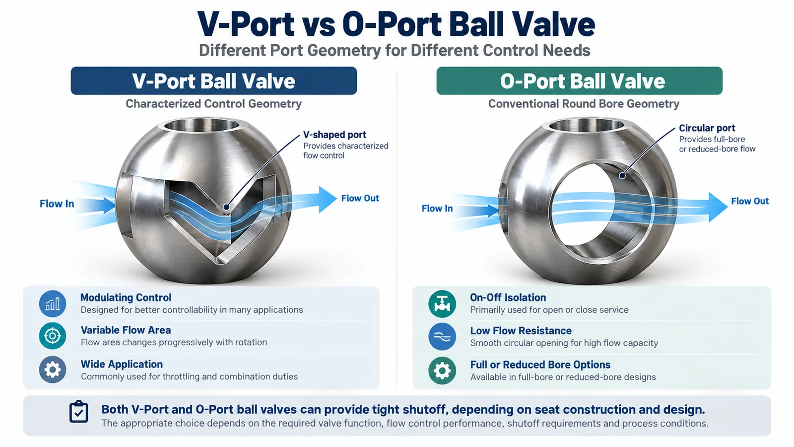
Define the valve function first. For frequent intermediate-position control, evaluate a characterized V-Port design and its specific Cv–travel data. For primarily open/closed duty, evaluate an appropriate O-Port isolation design. Both require product-specific pressure, temperature, material and leakage verification.
1. V-Port vs O-Port Ball Valve: Quick Comparison
A V-Port ball valve uses a characterized V-shaped notch or specially profiled port to influence how capacity changes with rotation. An O-Port ball valve uses a circular bore, commonly optimized for opening or closing the flow path. Some V-Port products use segmented rotary closure members; these must not be assumed mechanically identical to notched full-ball designs.
| Engineering factor | V-Port ball valve | O-Port ball valve |
|---|---|---|
| Funzione principale | Modulating control in suitable designs | On-off isolation in conventional designs |
| Geometria della porta | Characterized V-shaped/profiled opening | Circular through-bore |
| Flow characteristic | Specific notch and assembly determine curve | Conventional bore not typically characterized for fine modulation |
| Maximum Cv | Size and construction dependent | Bore and construction dependent |
| Rangeability | Evaluate trim-specific inherent characteristic | Do not presume useful throttling range |
| Tenuta | Seat-, design- and test-dependent | Seat-, design- and test-dependent |
| Azionamento | Modulating positioning often required | Manual or on-off actuation commonly used |
| Primary technical check | Cv–travel, installed range, actuation | Rated bore/Cv, pressure drop, leakage |
A generic port designation is not an approved valve specification. The supplier must show that the offered configuration meets the actual duty and documentation requirements.
2. How Does Port Geometry Affect Flow Control?
Port geometry influences the exposed opening as the ball rotates. Exposed area is not the same as Cv: internal flow losses, pressure recovery, the body/seat passages and fluid behavior influence capacity.
V-Port Geometry and Progressive Opening
A characterized V-Port can expose a relatively small passage near closure, then increase its opening as travel rises. Depending on the construction, the opening may be machined into a ball or formed by a segmented closure element. The result depends on notch profile, ball geometry, seat and body configuration, internal restrictions and flow direction.
It is incorrect to infer that every V-notch has the same flow curve, nominal port angle, minimum controllable travel or inherent rangeability. Request the actual curve for the selected trim. For product-specific construction and RFQ considerations, see the Valvola a sfera V-Port product information.
O-Port Geometry and Full-Bore or Reduced-Bore Designs
An O-Port contains a generally circular flow passage. As the ball rotates, the bore progressively aligns with or blocks the connecting pipe. A full-bore and a reduced-bore valve of the same nominal line size may have materially different capacity.
A conventional O-Port is a practical starting point for equipment isolation, process line shutoff and minimizing unnecessary full-open pressure loss when the bore is suitably selected. But simply holding such a valve half open does not demonstrate sustained throttling suitability.
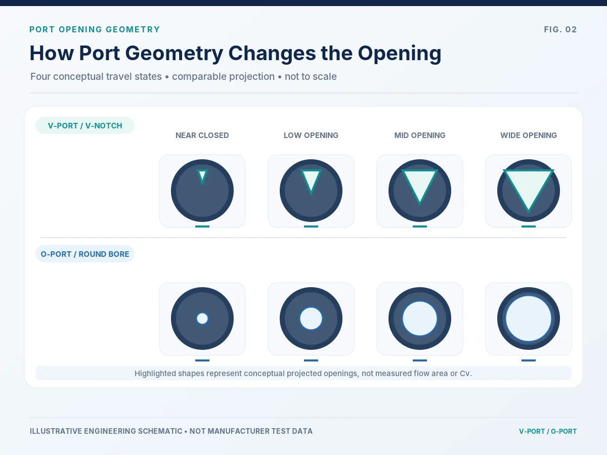
Port Shape Is Only One Part of the Flow Path
Two valves can share the same port label yet have different bore sizes, seat restrictions, support arrangements and end connections. The decision must use the complete manufacturer-specific valve design rather than a simplified image of the ball.
3. Flow Characteristic: How Does Cv Change with Valve Travel?
Inherent Cv–travel data describes how valve capacity changes with travel under specified constant differential-pressure conditions. For V-Port versus O-Port selection, ask where the required operating cases fall on the offered port geometry’s actual curve—not just whether a generic characteristic is called linear or equal-percentage.
V-Port Cv–Travel Characteristics
A V-Port may be designed to approximate an equal-percentage, linear or manufacturer-defined characteristic. Its intended curve depends on the detailed opening profile and surrounding flow passages. The word “characterized” does not prove one universal curve.
For a V-Port control-duty proposal, match minimum, normal and maximum flow cases to its exact notch/trim capacity curve and available travel.
O-Port Opening Behavior
The capacity change of a conventional round-bore isolation design can be strongly nonlinear over sections of rotation. Depending on service conditions, modest actuator movement may create inconveniently large or small flow changes. This is especially important where process control demands fine low-flow adjustment or stable repeatability.
Specially modified round-bore designs should be assessed by their actual manufacturer data rather than assumed to behave like ordinary isolation valves.
Low-flow control example (illustrative): An O-Port valve selected only for its full-open capacity may spend normal operation close to the lower end of useful travel. If a small stem movement changes flow more sharply than the controller can correct, the loop may hunt. Check the manufacturer’s actual Cv–travel curve, expected installed positions and positioner resolution before blaming the controller or specifying a V-Port replacement. A characterized V-Port is a candidate—not a cure for incorrect sizing.
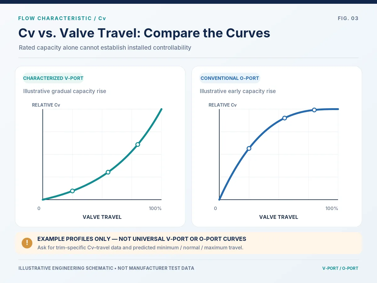
Curve interpretation: Do not infer a specific Cv, inherent rangeability, minimum controllable travel or required actuator position from this image. Request the actual offered valve/trim curve.
How to Read a Supplier Cv–Travel Curve
Before comparing curves, confirm whether the vertical axis shows absolute Cv/Kv or capacity normalized to each valve’s own rated value. Two curves can look similar when normalized yet represent very different maximum capacities. Mark the predicted minimum, normal and maximum operating positions on the actual offered trim curve; do not infer them from the illustrative chart above.
For a control-duty review, ask whether the valve has enough usable travel around the normal operating point and whether the required low-flow adjustment is larger than the combined positioning uncertainty of the actuator, positioner and feedback system. These are separate questions from full-open capacity.
Inherent Characteristics Are Not Installed Flow Curves
Changing valve differential pressure can shift the operating positions away from those suggested by a constant-ΔP curve. Compare each V-Port or O-Port candidate using the same process cases and the supplier’s actual Cv–travel data. The general linear-versus-equal-percentage characteristic and installed-gain discussion is separate from the port-geometry selection covered here.
4. Cv Comparison: Is an O-Port Ball Valve Always Higher Capacity?
A large unobstructed O-Port bore may provide considerable full-open flow capacity, but it is not technically valid to rank all O-Port designs above all V-Port designs by Cv. The result is construction and size specific.
Rated Cv vs Required Cv
Rated Cv describes capacity under stated conditions, often at full rated travel. Required Cv must be calculated from the actual process data. A useful evaluation includes corresponding pressure conditions, not simply a list of flow rates. Never compare bare numbers until the suppliers have identified Cv versus Kv, valve size, offered trim and rated travel.
For each operating case, collect fluid phase and properties at operating temperature, upstream and downstream pressure at the valve, and any relevant vapor-pressure or compressibility inputs. Startup, low-demand or upset cases may control sizing or damage risk even when they do not govern the maximum flow. The applicable calculation method must match the service fluid.
| Operating case | Buyer input | Engineering check |
|---|---|---|
| Flusso minimo | Flow, inlet/outlet pressure, fluid properties and temperature | Can the assembly regulate stably at low demand? |
| Flusso normale | Flow with corresponding P1/P2 and temperature | Does it operate in a controllable region of travel? |
| Flusso massimo | Maximum demand and corresponding pressures | Does the valve provide sufficient capacity without unacceptable limits? |
Maximum Cv Does Not Prove Good Controllability
Two candidate valves may both pass maximum required flow while the oversized candidate operates mainly close to its minimum practical opening. In that situation, actuator resolution, friction and small travel changes can dominate the process response. A bigger Cv may reduce rather than improve controllability.
Bid-comparison example (illustrative): Supplier A reports a higher rated Cv at full travel while Supplier B supplies a lower rated Cv with the predicted minimum, normal and maximum operating positions. The values cannot be ranked until both calculations use the same fluid properties, inlet and outlet pressure, control objective and valve size. Ask for both the rated-capacity basis and the position-by-position capacity data; otherwise, a seemingly favorable high-Cv quotation can conceal an oversized control valve.
Supplier Data Needed
Request exact valve and trim designation; rated Cv/Kv; capacity at representative travel positions; flow characteristic; selected sizing method; predicted travel at minimum, normal and maximum conditions; and appropriate hydraulic-limit analysis. For potential cavitation, flashing, choked flow or noise, request the calculations and relevant model-specific coefficients.
La control valve sizing guide provides a related project-data review pathway. IEC 60534-2-1 is an applicable control-valve sizing reference within its stated scope; its incompressible equations are not intended to be used indiscriminately for slurry, non-Newtonian or liquid-solid conveying service.
5. Rangeability: What Can the Valve Actually Control?
Rangeability is important where flow must be regulated from high to relatively low demand. A V-Port design can be characterized to achieve a useful range, but no single catalog ratio applies to every notch, seat or trim configuration.
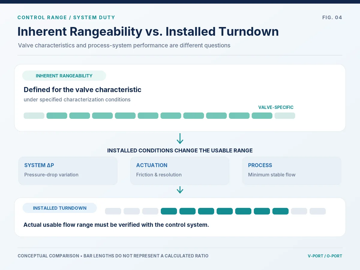
Inherent Rangeability vs Installed Turndown
Inherent rangeability is stated for a defined valve characteristic; installed turndown is the usable control range in the operating system. A characterized V-Port may have a documented inherent range, while a conventional O-Port isolation valve should not be assigned a useful modulation range without supplier evidence. Neither port designation establishes installed turndown. Verify the minimum controllable travel and the pressure-drop conditions for the specific offered assembly.
Low-Flow Positioning and Repeatability
A V-Port may expose a smaller, more progressively changing opening at low travel; a conventional O-Port may concentrate useful changes in a different portion of rotation. Neither geometry overcomes packing friction, shaft friction, seat loading or poor actuator resolution. Check low-flow positioning of the valve–actuator package, not port geometry alone.
Verify the Catalog Claim
Request the exact trim or port identification, supplier-stated inherent rangeability and basis, predicted installed control range, travel at key cases and assumed actuation performance. An attractive rangeability number alone does not establish the process operating turndown.
Low-flow screening hold point: if predicted minimum-flow control occurs near the supplier’s declared lower controllable-travel limit, request a revised sizing proposal or other engineered solution. Do not simply apply a catalog rangeability ratio to the required plant turndown. The bid should state the lowest controllable flow for the specified installed conditions and the assumptions behind it.
6. Shutoff and Seat Leakage: Can V-Port Valves Close Tightly?
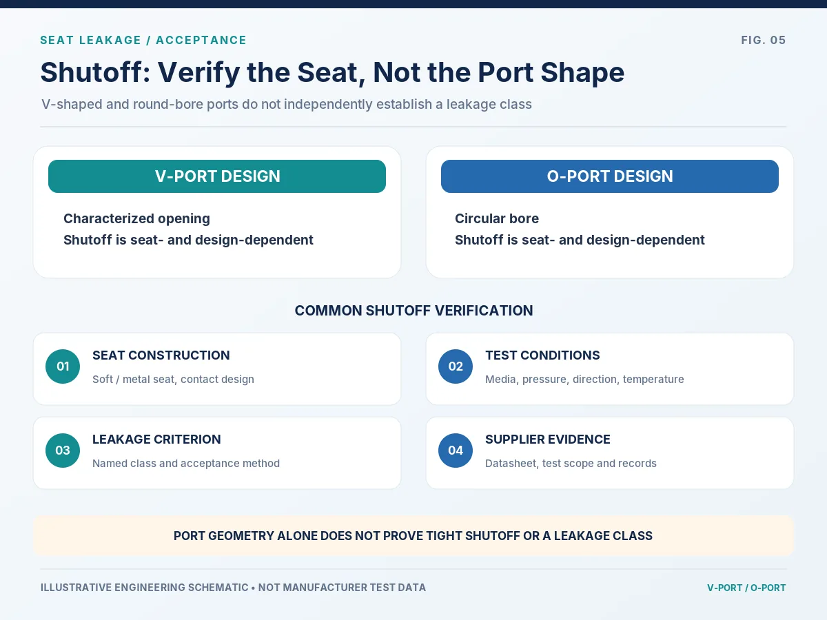
Yes, suitable V-Port constructions can be designed to meet specified leakage criteria. It is incorrect to assert that V-Port valves inherently have poor shutoff. Conversely, an O-Port designation alone does not establish a particular leakage class.
Seat Design and Shutoff Capability
Review the specified soft or metal seat system, contact geometry, direction of pressure loading, media cleanliness, solids, differential pressure, temperature, closing torque and expected throttling wear. These can materially affect leakage performance.
Leakage Criteria and Test Conditions
Where applicable, ANSI/FCI 70-2-2021 defines control-valve seat leakage classes and testing. Specify the required criterion, relevant edition, test pressure, medium, flow direction when relevant, acceptance limit and documentary evidence.
Documented manufacturer example: Bray’s V-Control ball valve product page lists a Class VI shutoff rating for its stated V-Port offering. This is Bray’s product-specific claim, not a test record or performance rating for Raymon Valve or for every V-Port design. Any required leakage class must be confirmed for the exact offered seat and valve assembly under the specified test conditions; it is not a guarantee of absolute zero service leakage.
Dedicated Isolation May Still Be Required
Where safety or maintenance isolation is involved, check the governing process and isolation philosophy. A control valve’s seat leakage class is not automatically evidence that it can replace a dedicated block valve. Consider service severity, failure consequences, maintenance access and whether continuous throttling affects closure performance.
Do not mix test objectives: seat-leakage acceptance addresses leakage past a closed trim under defined test conditions; shell pressure testing addresses pressure-boundary integrity; external stem/packing emissions require separate applicable assessment. Ask which tests will be performed on the offered valve, which are type or production tests, and which signed reports will be delivered. A catalog statement is not an order-specific test record.
Combined control-and-shutoff example (illustrative): A valve that passes a seat-leakage test before commissioning may see repeated throttling cycles, particles or seat-contact wear in service. If the line also needs positive maintenance isolation, the design review should verify whether a separate block valve is required by the plant isolation philosophy. Obtain the service-specific leakage criterion and test evidence instead of treating a control-valve leakage class as an isolation procedure.
7. Actuation, Torque and Control Accuracy
Modulating vs On-Off Actuation
A V-Port used for continuous modulation typically needs appropriate positioning capability, commonly through a suitable pneumatic or electric modulating actuator, feedback and positioner where required. A conventional O-Port isolation valve commonly uses manual or on-off actuation. These are typical arrangements, not universal constraints. The V-Port Ball Control Valve page provides related control-duty specification and supplier review inputs.
Positioning Performance
For stable modulation, evaluate resolution, deadband, hysteresis, repeatability, stroking time, control signals and movement under changing process loads. Incorrect positioning can produce hunting, overshoot or poor control even where port characterization is appropriate.
Torque and Actuator Evidence
Request breakaway, running and seating/unseating torque as relevant; maximum differential pressure; direction; seat construction; stroke time; operating frequency; supply limits; fail state; and project-defined margins. Do not specify actuator torque based only on nominal valve size or pressure class.
The actuator submittal should identify the controlling load case, minimum available utility supply, mounting/interface arrangement, end-of-travel settings and any required fail-position behavior. For control duty, request a package-level functional verification plan; a separately quoted actuator model is not proof that the assembled valve will position accurately through the required range.
Actuator review example (illustrative): An actuator may satisfy a catalog torque check at nominal supply pressure yet lose positioning margin when supply pressure falls to the specified minimum. For modulating duty, request the governing dynamic torque or load basis, minimum utility condition and expected positioning response of the assembled package. Recheck fail action and travel limits before accepting the package for the full operating envelope.
8. Which Valve Fits Different Process Conditions?
| Process need | Direzione preliminare | What must be checked |
|---|---|---|
| Continuous flow regulation | Evaluate V-Port | Exact Cv–travel, valve ΔP and actuator resolution |
| Primarily open/closed isolation | Evaluate O-Port | Shutoff criterion, cycling and bore capacity |
| Wide flow operating range | Evaluate characterized V-Port | Inherent rangeability and installed turndown |
| High full-open capacity | Compare actual designs | Bore dimensions, actual Cv and pressure loss |
| Frequent intermediate positioning | Review control-duty construction | Seat wear, torque and positioning behavior |
| Tight shutoff with modulation | Product-specific selection | Seat, leakage class and testing evidence |
| Abrasive particles or solids | Service-specific review | Particle size, concentration, erosion and fouling |
| Cavitation, flashing or high noise | Hydraulic review first | Pressure recovery, velocity, noise and severe-service alternatives |
Clean Liquid and Gas
Characterized rotary control may be an appropriate preliminary option for clean fluids requiring frequent modulation. Check sizing, actual operating ΔP, pressure recovery and travel distribution rather than selecting from the label alone.
Solids and Fouling
Some characterized rotary designs are considered for particle-bearing service, but suitability depends on particle size, concentration, hardness, fluid properties, local velocities and accumulation or erosion risks. A V-shaped opening is not inherently immune to blockage or wear.
Severe Pressure Reduction
If cavitation, flashing, high flow velocity or aerodynamic noise dominates, the priority may be severe-service sizing, specialized trim or a different valve/pressure-reduction arrangement. Neither V-Port nor O-Port is an automatic answer to severe hydraulic conditions.
Pressure–Temperature, Material and Installation Screening
Once a port concept appears feasible, check that the actual body, closure element, seat, packing and gasket match the full process envelope. Review pressure-temperature rating, fluid chemistry and concentration, temperature transients, solids, cleaning agents, flow direction, piping interfaces and available maintenance access. A compatible body alloy alone does not qualify the seat or stem sealing materials.
A pressure class designation is not a single allowable operating pressure independent of temperature and material. For the offered valve, obtain the applicable pressure–temperature rating, end-connection and body construction basis, plus separate operating limits for seat, packing, gasket and actuator components. Chemical compatibility should consider fluid composition, concentration, cleaning chemicals, solids and credible temperature excursions rather than only the valve body’s alloy name.
The same valve can have different practical limits under continuous throttling and closed-position differential pressure. Request the manufacturer’s operating envelope and any service-specific limits for the offered construction rather than carrying across a rating from another size or seat option.
Common Symptoms, Likely Risks and Evidence to Request
These are screening signals, not field diagnoses. Actual corrective work requires safe isolation and a site-approved inspection procedure.
| Observed concern | Possible design / operating cause | Evidence or review action |
|---|---|---|
| Low-flow hunting or poor repeatability | Excess capacity, friction, deadband or high installed gain | Check predicted travel, positioner response and actual Cv–travel data |
| Leakage after repeated modulation | Seat wear, solids or unsuitable closure load | Review seat materials, duty history and specified leakage acceptance |
| Unexpectedly high actuator demand | Dynamic pressure load, seat friction or incorrect sizing basis | Request valve torque-versus-position or bounding duty data and actuator calculation |
| Noise, vibration or early trim damage | High velocity, cavitation, flashing or erosion | Request operating-case hydraulic review and suitable alternative designs |
9. V-Port vs O-Port Selection Workflow
Work through the engineering decision in a consistent sequence:
- Define the function: isolation, continuous modulation, occasional throttling or combined duty.
- Collect service data: fluid phase and composition, pressures, temperatures, flows and abnormal conditions.
- Calculate required Cv/Kv: use a suitable method for minimum, normal and maximum cases.
- Review characterized geometry: request the exact proposed bore/notch and Cv–travel relationship.
- Evaluate installed operation: check valve ΔP, predicted travel and acceptable control response.
- Specify shutoff: identify leakage criterion and whether isolation needs a separate valve.
- Review actuation: torque, positioning, speed, signal, fail state and supply constraints.
- Check service risks: corrosion, solids, erosion, cavitation, flashing, noise and maintenance.
- Normalize supplier evidence: compare calculations, test criteria, ITP and technical deviations.
- Approve a specific configuration: follow the controlled project datasheet, drawings and acceptance documents.
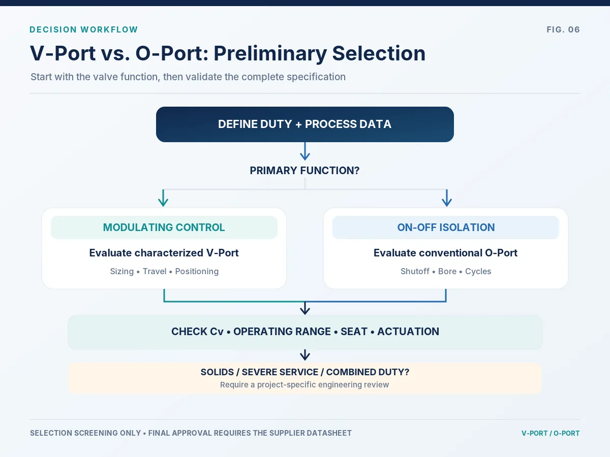
The flowchart is a screening aid. It is not a substitute for a sizing calculation, a supplier design review or responsible-engineer approval.
Selection hold points: do not treat the technical choice as closed if the proposed trim cannot be identified, any required operating case is missing, the shutoff test criterion is undefined, or actuation data do not cover the governing differential-pressure and utility-supply cases. Track each gap in the supplier clarification and deviation register until the responsible project reviewer accepts its resolution.
10. RFQ Checklist: What Should Buyers Request?
Technical bid comparison requires all suppliers to use the same operating cases, acceptance criteria and document basis. Missing process assumptions can produce apparently similar quotes for materially different solutions.
| RFQ field | Buyer provides | Supplier should confirm |
|---|---|---|
| Funzione della valvola | Isolation, modulation or combination | Proposed construction and limitations |
| Fluid | Phase, composition, contamination and solids | Material, trim and seat compatibility |
| Operating points | Minimum / normal / maximum flow | Required Cv/Kv and predicted travel |
| Pressure conditions | P1 and P2 for each case | Valve ΔP and hydraulic limitations |
| Temperatures | Normal, design and upset conditions | Rating and seat envelope |
| Connessioni | Size, class/PN, ends, face-to-face | Mechanical interface and bore |
| Caratteristica | Required control response | Exact Cv–travel characteristic |
| Operating range | Minimum controllable to maximum flow | Rangeability basis and installed review |
| Tenuta | Leakage class and acceptance method | Seat design and test documents |
| Azionamento | Signal, utility, speed, fail state | Torque basis and actuator sizing |
| Severe-service issues | Cavitation, flashing, noise, solids | Application-specific checks |
| Ispezione | Standards, witness points, ITP | Procedures and records |
| Deviazioni | Owner specifications, exceptions | Written deviation list |
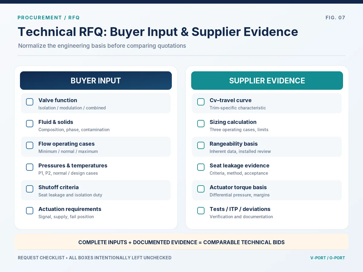
Technical Bid Normalization: Evidence and Release Gates
For competing V-Port and O-Port proposals, obtain a tag-linked requirement-to-evidence response. “Complies” without a part number, calculation, test method or document reference should remain an open technical point.
| Bid-review gate | Required supplier evidence | If missing or inconsistent |
|---|---|---|
| Offered geometry and capacity | Exact valve/trim identification, rated Cv/Kv and Cv–travel curve for control duty | Clarify before accepting claimed control performance |
| Operating-case suitability | Sizing sheet with matched flow, P1/P2, fluid properties and predicted travel | Hold the sizing decision until governing cases are covered |
| Shutoff and seat life considerations | Specified leakage acceptance, seat material and applicable test scope | Separate isolation requirement or revise seat/test specification |
| Hydraulic and material limits | Service envelope plus cavitation, flashing, noise, erosion or corrosion review when applicable | Obtain a justified alternative or documented deviation |
| Attuatore e controlli | Torque basis, utility assumptions, fail action, accessories and functional-test plan | Request complete package calculation and controls clarification |
| Ispezione e documentazione | Proposed ITP, test records, materials/traceability scope and deviation schedule | Identify hold/witness points and agreed turnover deliverables before release |
Release criterion: for each proposed valve tag, the approved datasheet, referenced sizing calculation, applicable Cv–travel curve (for control duty), specified seat-leakage acceptance and actuator sizing basis must identify the same offered configuration. Unresolved discrepancies stay on the technical clarification/hold-point list before purchase approval. A hold point means suitability has not yet been demonstrated, not necessarily that the valve is unsuitable; close it through documented evidence, an approved deviation or revised selection.
Before purchase-order release: confirm that each deviation has a disposition, each acceptance test identifies its method and scope, and every quoted actuator/positioner accessory appears on the same assembly drawing and document index as the selected valve. A test method, catalog curve or material certificate for a different configuration is supporting background—not acceptance evidence for the supplied tag.
Supplier Comparison Example
In an illustrative procurement scenario, Supplier A quotes a V-Port valve with only a rated Cv and generic brochure. Supplier B submits the identified port configuration, Cv-versus-travel data, three operating-case calculations and a documented actuator basis. The quotations cannot be treated as technically equivalent until missing evidence has been clarified. This is a hypothetical decision example, not a Raymon Valve project claim.
11. Frequently Asked Questions
What is the main difference between a V-Port and an O-Port ball valve?
A V-Port uses a characterized opening whose geometry is intended to shape how flow capacity changes with travel; it is often considered for modulation. A conventional O-Port has a circular through-bore and is commonly selected for on-off isolation. Compare the actual port design, Cv–travel data, seat construction and service conditions rather than the label alone.
Is a V-Port ball valve better for flow control?
For repeated modulating duty, a suitably sized and characterized V-Port is often a better starting point than a standard round-bore isolation valve. It is not automatically better in every system: predicted travel, installed differential pressure, positioner response, hydraulic limits and shutoff duty must all be verified.
Does an O-Port ball valve have a higher Cv than a V-Port ball valve?
Not as a universal rule. Rated Cv depends on actual bore, trim, body passages, seats and size. A full-bore O-Port may have high open capacity, but only model-specific Cv data and equivalent sizing conditions can establish which proposed valve has more capacity.
What is the typical rangeability of a V-Port ball valve?
There is no single rangeability value that applies to all V-Port valves. Ask for the manufacturer’s inherent rangeability of the exact characterized port and verify separately whether the installed system can achieve the required minimum-to-maximum controlled flow range.
Can a V-Port ball valve provide tight shutoff?
Yes, when its particular seat and closure design meets the specified leakage acceptance criteria. Some manufacturers publish tight-shutoff ratings for identified V-Port products, but these do not apply to every model. Define the leakage standard, test conditions and acceptance record for the exact valve being quoted.
Can a standard O-Port ball valve be used for throttling?
It can be positioned partly open, but this does not prove suitability for repeated throttling. Local velocity, erosion, seat exposure, actuator behavior and control resolution can be limiting. Obtain explicit control-duty approval and capacity data from the manufacturer or consider a characterized valve.
12. Final Selection Guidance
Select the port geometry around the function, not the other way around. Characterized V-Port options warrant assessment when continuous modulation and predictable capacity change are important. Conventional O-Port designs warrant assessment where isolation and full-open flow capacity dominate.
Neither choice is inherently superior in maximum Cv, leakage performance, temperature capability or service life. Final approval must follow process sizing, manufacturer-specific data, seat and material review, actuator selection and test acceptance.
For conventional isolation designs and other construction options, explore the Valvole a sfera product category.
Request V-Port vs O-Port Ball Valve Selection Review
Send the fluid composition and phase, minimum/normal/maximum flow with the corresponding P1 and P2, design and operating temperatures, line size and ends, required control range, shutoff criterion, actuation method and fail action. Attach any current datasheet, Cv–travel curve, sizing sheet or technical deviations. Ask for an order-specific review of the proposed port, seat and actuator package—not an unqualified claim based on valve type.
Richiedi revisione selezione valvolaThis article provides preliminary technical guidance and procurement questions, not approved sizing or a product-specific guarantee. It does not assign a final Cv, port characteristic, valve size, rangeability, leakage class, actuator torque or certification to any Raymon Valve product. The publisher is Raymon Valve as an organization; no named licensed engineer or independent test witness is represented here. Project documents, verified supplier data, actual model-specific test records and applicable standard editions govern final selection. Special media may require different or validated sizing methods.
Technical References
- IEC 60534-2-1:2011 — Flow capacity: installed-condition sizing equations.
- IEC 60534-2-4:2009 — Inherent flow characteristics and rangeability.
- ISA75.11 — Control valve flow characteristics and rangeability.
- Fluid Controls Institute — ANSI/FCI 70-2-2021 control valve seat leakage testing.
For company background and a review of available industrial valve categories, visit Chi siamo.
 Italian
 English
 German
 Arabic
 French
 Spanish
 Portuguese
 Russian