
Industrial Check Valve Installation · Engineering Guide
Check valves can be installed in horizontal or vertical pipelines only where the exact model and normal flow direction are approved by the manufacturer. Vertical upward approval does not automatically permit vertical downward flow. Gravity, spring loading and closure-element travel affect opening and return to the seat; minimum flow and pump shutdown behavior affect stability. To approve the installation, match the body flow arrow and mounting position to the controlled IOM and drawing, then check actual flow conditions, clearances and the required operating evidence. This guide provides the orientation matrix and RFQ checks needed for that review.
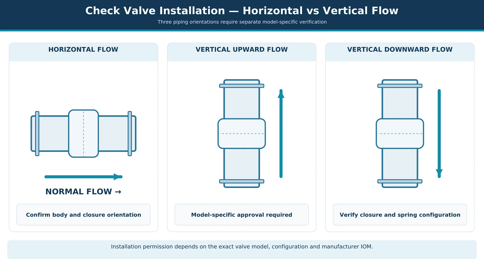
Can a Check Valve Be Installed Horizontally or Vertically?
Check valves open in response to forward-flow forces and return toward the seat when those forces decay or reverse. The closure element may rotate on a hinge or move along a guide. Because gravity acts vertically, changing the pipe orientation can change the opening and return moments or forces even though the valve size, pressure class and end connections remain unchanged. The decision must therefore identify the actual closure mechanism, not only the valve type printed on the datasheet.
Horizontal, Vertical Upward and Vertical Downward Flow
Three installation arrangements require separate consideration:
- Horizontal installation: Normal flow travels through a horizontal pipe. The approved hinge, guide or bonnet orientation must be maintained.
- Vertical upward installation: Normal flow travels upward. Gravity may assist closure for certain constructions, although opening requires sufficient fluid force.
- Vertical downward installation: Normal flow travels downward. Gravity may oppose spring-driven closure in some designs, making the exact construction and spring configuration particularly important.
An inclined line creates another set of conditions because the gravity component acting along the closure element’s travel direction changes with angle.
Quick Installation Orientation Matrix
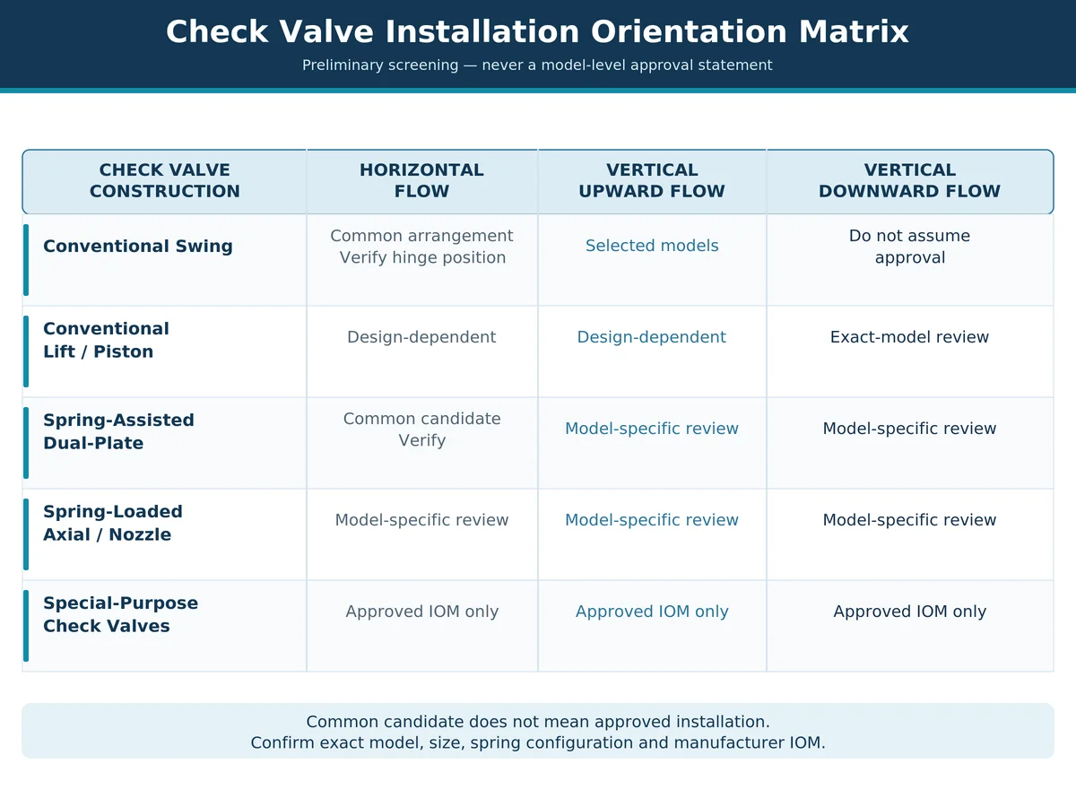
Table 1 — Preliminary Check Valve Installation Orientation Matrix
| Check Valve Construction | Horizontal Flow | Vertical Upward Flow | Vertical Downward Flow |
|---|---|---|---|
| Conventional swing check valve | Common arrangement; confirm hinge and cover position | Some models approved | Do not assume approval |
| Conventional lift or piston check valve | Depends on body pattern and guide direction | Possible for suitable constructions | Requires model-specific verification |
| Spring-assisted dual-plate check valve | Candidato comune | Possible where approved | Requires spring and closure verification |
| Spring-loaded axial-flow or nozzle check valve | Often a candidate | Possible where approved | Possible for specifically approved designs |
| Special-purpose check valve | Follow approved configuration | Follow approved configuration | Follow approved configuration |
Engineering limitation: This matrix provides preliminary screening guidance, not installation permission. The manufacturer’s controlled installation, operation and maintenance manual (IOM), exact model configuration and project specification govern final approval.
Manufacturer evidence — not transferable approval. The examples below show why orientation must be checked against an identifiable model and document rather than a check-valve family name.
Manufacturer Evidence & Applicability (examples, not Raymon Valve product claims)
| Model & Source | What the Source Supports | Restrictions & Evidence Limit |
|---|---|---|
| Flomatic 92LS Manufacturer product page | Horizontal or vertical upward-flow installation for the documented lever-and-spring swing-check model. | Factory consultation for vertical mounting; the webpage is not a controlled approval for another valve model, size option or brand. |
| Val-Matic Silent Check Valve IOM manual SCV-OM1-4 | Horizontal and vertical (flow-up or flow-down) arrangements for the wafer/globe-style products covered by the manual. | Clean-water service; suspended solids and hazardous fluids excluded. Vertical-down duty for 14 in. and larger requires special-spring review and factory consultation. |
Record the exact source and controlled IOM revision used for the offered valve. Neither third-party example proves Raymon Valve installation approval, model performance, certification or compatibility with another fluid.
Horizontal vs Vertical Check Valve Installation
Horizontal Installation — Closure Movement and Body Position
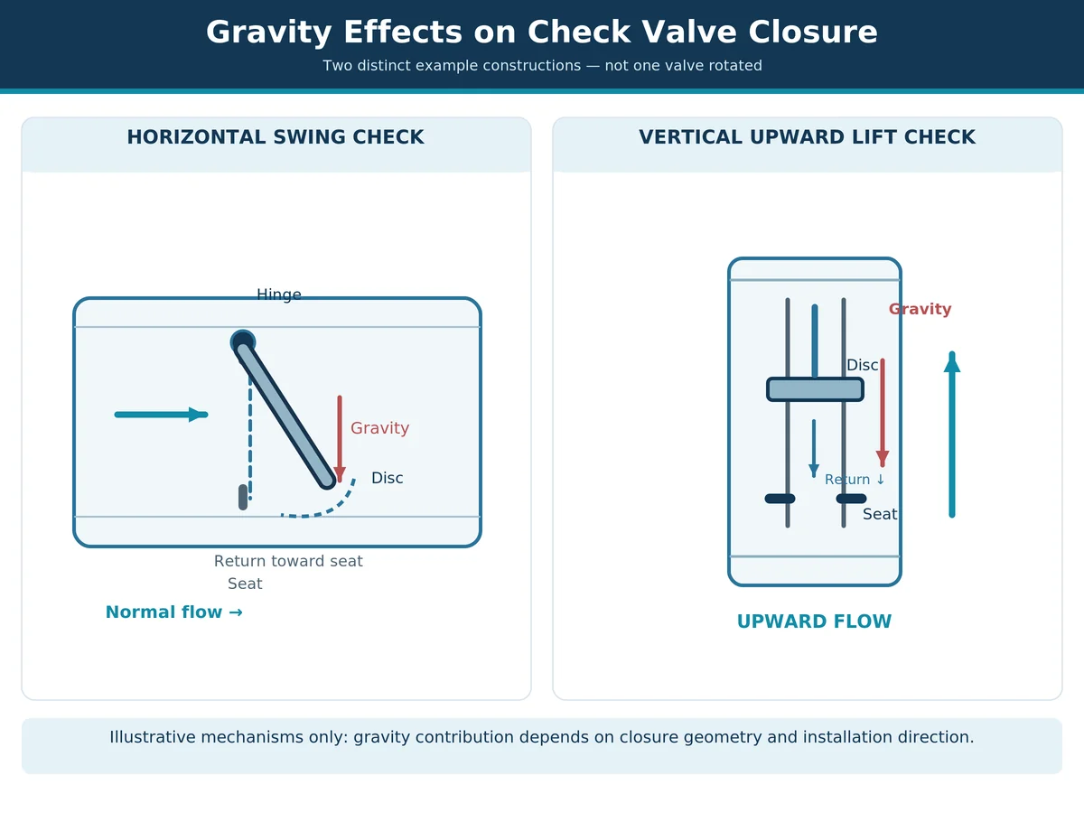
Horizontal piping is a common arrangement for industrial check valves, but it does not eliminate orientation requirements. A conventional swing check valve typically uses a hinged disc that rotates away from the seat as forward flow develops. In many standard configurations, the hinge is positioned so that the disc can return toward the seat under gravity when forward flow decreases.
Rotating the valve body around the horizontal pipe axis may change how gravity acts on the disc. An unintended hinge position may interfere with closing behavior. For guided spring-loaded designs, body rotation may have a different effect because the spring provides a defined closing force and the closure element follows a guide. The approved drawing should establish whether the valve requires a particular top, hinge, shaft or bonnet position.
Installation review example: A horizontal spool fits the required face-to-face dimension, but the proposed bonnet or hinge position differs from the manufacturer’s drawing to avoid an obstruction. The mechanical fit alone does not approve the rotation. Record the proposed body position, compare the hinge/guide axis with the controlled drawing, and request written confirmation or revise the spool layout before installation.
Vertical Upward Flow — When Gravity May Assist Closure
In a vertical upward-flow arrangement, process fluid travels upward through the valve. For an upward-opening closure element, the fluid must overcome opposing closing forces to initiate and maintain opening. Gravity can help return the element toward its seat as upward flow decays. However, this benefit depends on construction.
A swing check approved for upward flow may close differently from a guided lift check or an axial-flow check. Movement direction, hinge geometry, travel, spring force and flow path all matter. The question is not simply whether gravity helps closure: it is whether the valve opens sufficiently at minimum required flow and returns to its seat under actual operating and shutdown conditions. Vertical upward installation therefore requires exact-model documentation and applicable opening-performance data.
Vertical Downward Flow — Why Additional Approval Is Needed
Vertical downward flow deserves particular attention because gravity may change the closing-force balance. In certain axial or guided configurations, the closure element moves downward as forward flow opens the valve. Gravity may act in the opening direction, while spring force must return the element upward during closure. Other internal arrangements have different travel paths and force balances.
A spring-loaded check valve may be specifically designed for this condition, but the presence of a spring is not sufficient evidence of suitability. The manufacturer may need to confirm spring configuration, size, closing travel, differential pressure and duty. For instance, the Val-Matic manual identifies additional spring requirements for certain larger valves in downward-flow service. Those requirements apply to the documented product family, not all spring-loaded check valves. Where the manufacturer does not explicitly authorize the proposed configuration, treat installation approval as open until resolved.
Approval question: Does the written model-specific instruction permit this normal flow direction and the supplied spring configuration?
Inclined Piping and Nonstandard Installation Positions
An inclined pipe should not automatically be classified as horizontal or vertical. With changing inclination, the component of gravity acting along or around closure-element motion changes. This may affect opening force, return behavior and intermediate stability. Record the proposed inclination, normal flow direction and valve body rotation. Submit them for manufacturer review whenever approved instructions do not explicitly cover the arrangement.
How Gravity and Spring Assistance Affect Check Valve Closure
Gravity-Dependent Disc Return
A gravity-assisted closure mechanism uses the weight of the moving element to contribute to closing force or moment. For a swing check valve, the disc rotates about a hinge; gravitational closing moment depends on disc mass distribution, hinge geometry and mounting direction. For a guided closure element, gravity acts according to the travel axis.
This explains why changing installation orientation may alter behavior even when nominal size and pressure rating remain unchanged. Gravity alone does not determine the closing response: seat geometry, hinge or guide friction, deposits, reverse differential pressure and supplementary closing mechanisms can also influence the final movement.
Spring-Assisted Closing Force
A spring-assisted check valve introduces mechanical closing force that can act before substantial reverse flow develops. Depending on design, the spring assists a rotating disc, two pivoted plates or a guided linear-moving element. It may reduce dependence on gravity while also changing the fluid force required for opening.
A stronger spring is not automatically better: it may increase the differential needed for initial opening or change the flow required for a stable opening position. That can affect pressure loss and, in a low-flow duty, leave the closure element partially open. Spring changes also alter closing response, so any proposed spring substitution needs the exact model’s supported opening and shutdown basis—not a generic assumption that faster closing eliminates surge.
How Installation Orientation Changes the Force Balance
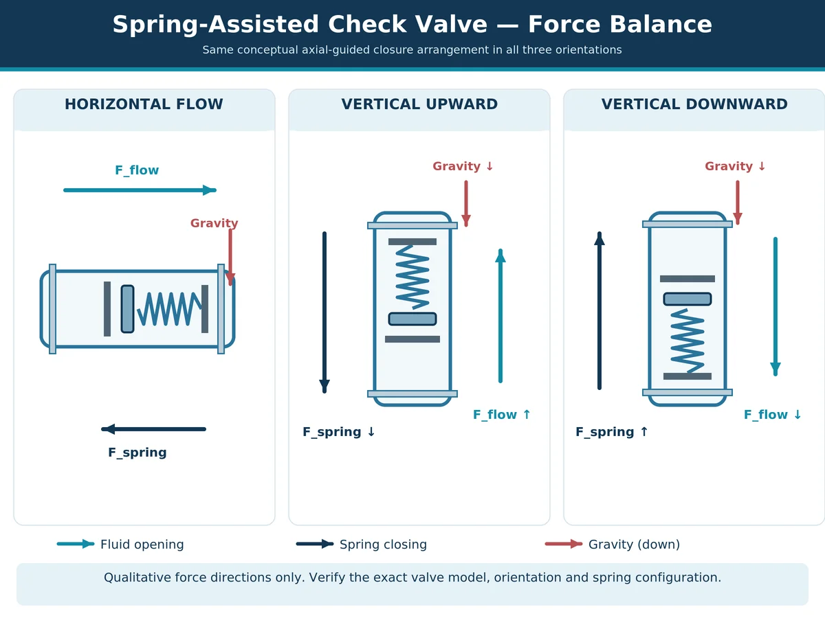
The closure element’s movement is governed by combined fluid loading, spring force, gravity, friction and dynamic motion. Forward flow must create enough opening force or moment to overcome the forces resisting opening. As forward flow decays, that force balance changes and the element approaches its seat.
In vertical piping, gravity may act with or against spring-driven return according to internal geometry. In horizontal piping, gravity may influence hinge moment, sliding friction or contact loads differently. The same spring configuration should not automatically be assumed suitable for every orientation. Distinguish initial cracking, sustained normal opening, minimum-flow behavior and shutdown.
For the axial spring-return concept diagram below, forward fluid force moves the closure element away from its upstream seat and the spring pushes it back toward the seat. Gravity acts downward in every installation: it aligns with the spring-return direction in a vertical upward-flow arrangement and opposes spring return in the illustrated vertical downward-flow arrangement. This is a qualitative diagram of one mechanism, not a force calculation or a general rule for hinged or dual-plate check valves. Rotating a particular assembly does not, by itself, change its spring rate; it changes the gravitational contribution relative to the opening/closing travel.
Why Cracking Pressure Does Not Prove Stable Opening
Cracking pressure is the differential pressure at which a closure element begins to open under specified conditions. It is not the differential pressure needed to hold it fully open. A valve may crack open at a relatively low differential while remaining partly open in normal operation. When fluid force is insufficient to maintain a stable position, the element may move repeatedly, contact its stop or seat, and experience wear.
Therefore, installation approval should be informed by the exact valve’s opening characteristic, minimum stable-flow guidance and pressure-drop data where applicable. The check valve sizing and stable-opening guide explains why matching nominal line size is not sufficient.
Minimum evidence to request: A stated cracking condition should be paired, where available, with the exact model’s flow-versus-pressure-drop data, expected degree of opening at the minimum continuous flow, and manufacturer guidance on stable operation. If those data are unavailable, record the stability question as an unresolved technical item; do not treat a nominal bore match or a low cracking-pressure value as proof of correct selection.
Installation Orientation by Check Valve Construction
Construction selection also depends on the fluid. Suspended solids, viscosity, fouling, corrosive constituents, phase changes and operating temperature may affect moving-element friction, seat condition and spring performance. Installation-orientation permission for a clean-water reference model must not be transferred to slurry, hazardous fluids or other process media without product-specific confirmation.
Valvole di ritegno a battente
Conventional swing checks use a hinged disc rotating through an arc. Their requirements depend on hinge orientation, disc mass, travel, any spring or counterweight, and gravity. Horizontal installation is common. Some models are approved for vertical upward flow, but vertical downward flow cannot be inferred from the general swing-check designation. Spring-assisted or lever-equipped variants require specific confirmation.
Conventional Lift and Piston Check Valves
Lift and piston check valves use closure elements moving along guides. The direction of guided motion matters because gravity can assist or oppose opening and return. A conventional globe-pattern gravity-return lift check is not interchangeable with a purpose-designed spring-assisted inline check simply because both contain guided discs or pistons. Review the internal section, guide axis, spring configuration and approved body orientation. For a focused comparison of the two closure mechanisms, see the confronto tra valvole di ritegno a battente e a sollevamento.
Dual-Plate Wafer Check Valves
Dual-plate checks generally use two spring-assisted plates rotating around a central hinge arrangement. Compactness can be useful where space is limited, but allowable orientation is model-specific. Spring characteristics, plate travel, shaft arrangement, flow distribution and flange compatibility should be checked. Where flow is low or fluctuating, stable plate opening requires attention.
Spring-Loaded Axial-Flow and Nozzle Check Valves
Axial-flow and nozzle-style designs generally use an in-line spring-assisted element. Some permit multiple orientations, potentially including vertical downward flow, but this is not universal. Exact size, spring configuration, guide geometry and intended fluid service determine the permissible arrangement. The controlled installation instructions and model-specific performance data remain authoritative.
Why Valve Type Names Cannot Confirm Installation Approval
Names such as “silent,” “non-slam,” “spring-loaded” or “vertical check valve” describe broad characteristics or intended applications. They do not independently confirm a particular mounting arrangement. Record exact model, size, revision and options on the procurement documents. See the industrial check valve product range for construction categories; final orientation approval still requires model-specific documentation.
Why Correct Installation Orientation Does Not Guarantee Stable Operation
Minimum Flow and Partial Opening
A valve may be approved for vertical installation and still operate poorly if flow is too low. Its closure element needs sufficient fluid force to achieve and maintain stable opening. Variable-speed pumps, intermittent processes and parallel pumping systems can operate substantially below design flow. A nominal line-size match therefore cannot establish stable opening. Review minimum, normal and maximum flow against the exact model’s characteristics.
Low-flow review example: A vertical pump discharge check valve is quiet at design flow but rattles when a variable-speed pump turns down. The symptom could indicate an unstable partly open closure element rather than incorrect mounting. Verify the operating flow and pressure history, compare them with the offered model’s stable-opening guidance, and inspect the hinge or guide condition under approved isolation procedures. Do not prescribe a smaller valve or stronger spring without checking pressure drop and closing response.
Gravity, Spring Force and Disc Flutter
Flutter or chatter can arise when forces acting on the closure element fluctuate near an unstable position. Contributors include insufficient opening force, pulsation, disturbed inlet flow, spring characteristics, friction and wear. Orientation can contribute by changing gravity loads or motion resistance, but sound alone does not establish improper orientation. Operating evidence and inspection are needed to distinguish causes.
Pump Shutdown, Reverse Flow and Closing Response
When a pump stops, forward flow may decelerate and reverse depending on the piping system. Closing response depends on travel, moving mass, spring force, gravity, friction and the changing differential pressure. If reverse velocity develops before seating, its interruption can contribute to a pressure transient. Thus, correct mounting does not ensure acceptable shutdown performance. High-consequence liquid duties may need hydraulic transient analysis; compressible or multiphase systems require appropriate models.
Shutdown review example: A supplier approves vertical upward mounting and quotes an acceptable steady pressure drop, but the station has parallel pumps and rapid trip conditions. Those two approvals cannot establish the resulting reverse velocity or pressure excursion. Obtain valve-response data relevant to the offered size and spring, then have the responsible system engineer evaluate the pump coast-down and piping profile before accepting the shutdown duty.
When System Transient Review Is Necessary
Additional system-level review may be justified for long liquid lines, rapid pump trips, major elevation changes, parallel pumps or a known surge history. Orientation approval does not substitute for that analysis. A product described as “non-slam” is not guaranteed to eliminate water hammer in every system. For field evidence and diagnosis, use the check valve chatter versus slamming guide.
For procurement, separate manufacturer valve-response evidence (travel, closing characteristics, relevant test or calculation conditions) from the system transient assessment (pump coast-down or trip, line profile, fluid properties, and potential reverse velocity). The supplier’s closing-characteristic data can be an input to the project analysis, but the supplier’s orientation approval alone is not a system surge assessment.
Installation Details That Affect Check Valve Performance
Flow Arrow, Hinge Position and Approved Body Orientation
The body arrow indicates intended normal forward flow. It should align with process flow, not the reverse flow being prevented. But correct arrow alignment does not establish permission for vertical mounting or arbitrary bonnet rotation. Verify the approved body position, hinge or guide orientation, model and installation drawing.
Pump Discharge, Elbows and Flow Disturbance
Pumps, elbows, tees, reducers and other nearby fittings may cause nonuniform or disturbed flow. These conditions can affect closure stability, particularly at low or varying flow. Do not apply a universal straight-pipe distance to all check valve constructions. Follow the exact-model IOM, and review deviations where the required arrangement cannot be provided.
Example of a specific instruction: The referenced Val-Matic wafer/globe Silent Check Valve IOM recommends three upstream pipe diameters of straight run for its documented valve family. This illustrates why the controlled IOM matters; 3D is not a universal check-valve clearance rule and must not override the requirements of another model or the project piping layout.
Flange Alignment, Pipe Support and Clearance
Mechanical installation must satisfy the approved piping design. Confirm end-connection compatibility, dimensions, gasket arrangement, alignment, supports and available space. Moving discs or other internals must not interfere with adjacent valves or equipment. Connected piping should not impose unapproved loads or distortion on the valve body.
Where installed next to a butterfly or isolation valve, verify that discs, stems and other moving parts cannot enter the check valve’s required internal clearance. Check the mating-flange bore, seating support, gasket arrangement and face requirements against the supplied model’s drawing. For constrained skids, the installation drawing should show these interfaces rather than relying on nominal face-to-face dimensions alone.
Maintenance Access and Installation Restrictions
Plan access to covers, hinges, springs, guides, lifting points and removable internals where applicable. Some valves need removal space for maintenance. If the approved valve cannot fit or be maintained in the proposed envelope, resolve the interface before procurement rather than selecting an unsupported alternate orientation.
Common Problems Caused by Incorrect Check Valve Orientation
An unsuitable orientation can contribute to incomplete closure, unstable movement, abnormal wear or leakage, but similar symptoms may arise from operating conditions, damage, deposits or sizing. Match each symptom with evidence before assigning a cause.
Matrice di rischio e verifica dell'installazione
Table 2 — Check Valve Installation Failure Risk and Verification
| Observed Problem | Possible Contributors | Required Verification |
|---|---|---|
| Disc fails to close consistently | Unsupported orientation, friction, gravity interaction or spring configuration | IOM, sectional drawing, operating data and internal condition |
| Repeated chatter or flutter | Low flow, disturbed inlet flow, unstable partial opening or spring behavior | Flow history, pressure differential, piping layout and model-specific stability data |
| Closing impact after pump shutdown | Reverse-flow exposure, delayed closure or system transient | Pump trip sequence, pressure history, valve dynamic data and piping profile |
| Reverse leakage | Debris, worn seat, misalignment or incomplete closure | Seat condition, cleanliness, installation records and specified leakage criteria |
| Abnormal hinge, guide or spring wear | Repeated movement, friction, deposits, corrosion or orientation-related loading | Inspection records, component condition, service history and approved configuration |
This matrix identifies investigation routes. A symptom is not proof of a single root cause.
Incomplete Closure or Reverse Leakage
If a valve fails to seat fully, check installation geometry and the physical condition of the mechanism. Verify the documented orientation and appropriate spring, hinge or guide. Debris, deposits, damaged seats and wear can also prevent full closure. Leakage must be evaluated against specified test conditions and acceptance criteria, not an assumption of absolute tightness. A shop seat test evaluates closure leakage under specified test conditions; it does not demonstrate minimum-flow stability, site-mounted orientation approval or pump-trip behavior. Require separate evidence for each question.
Disc Instability and Repeated Wear
Repeated motion can accelerate wear of hinges, guides, pins, stops, seats or springs. Possible causes include low flow, pulsation, unsuitable clearance and contaminated service. Before changing valve type or replacing parts, compare the operating history with exact-model requirements.
How to Verify Installation-Related Causes
Identify the installed valve, then compare as-built flow direction, line inclination, body rotation, internal configuration and service conditions with controlled drawings and IOM. If a discrepancy exists, record an engineering deviation and determine corrective action through responsible site procedures.
Limite di sicurezza: Inspection, isolation, depressurization and maintenance must follow approved facility procedures. Do not open, rotate, adjust or remove a pressurized check valve based on this article.
How to Verify Check Valve Orientation Before Installation
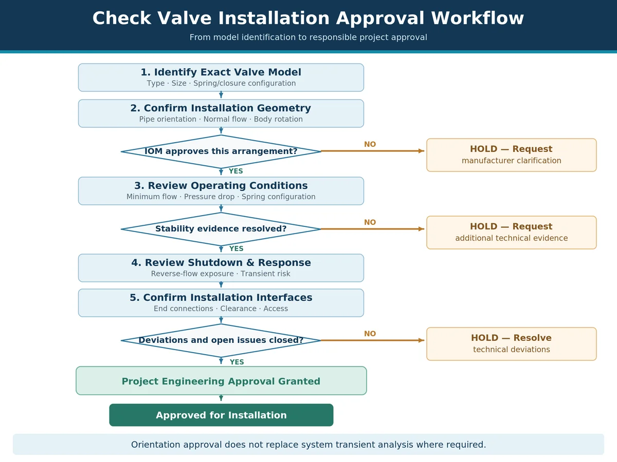
Review the Manufacturer’s IOM and Controlled Drawings
Start with the IOM for the exact supplied model. Controlled drawings should state permitted pipe orientation, normal flow direction and any restrictions on body rotation or closure-element alignment. Generic catalogue statements are useful for screening, but cannot replace model-specific instructions. Request clarification when information conflicts with the proposed installation.
Check whether the permission is limited to a particular size range, clean-water service, spring option or installation axis. Record the document identifier and revision: a generic product-family PDF without a model match is supporting background, not final approval evidence.
Confirm Model, Size, Spring Configuration and Flow Direction
Record supplier, model, nominal size, pressure class or PN, end connection and construction revision. When a spring is present, identify its actual configuration. Optional heavy-duty springs or alternate internals must be reflected in the approved offer, drawing and parts identification as relevant. Acceptance must apply to the supplied configuration, not another model in the same family.
Verify Installation Against the Project Specification
Confirm non-return duty, fluid, flow range, pressure, temperature and shut-off requirements. Review actual pipe direction, adjacent equipment and pump or compressor duty. Verify applicable project piping specifications and standards. ASME B16.34 addresses valve requirements within its scope (official page currently lists B16.34-2025), while ASME B31.3 provides a process-piping code framework (official page currently lists B31.3-2024). Neither grants model-specific mounting permission; verify project-approved editions and contract precedence.
Record Open Issues and Required Engineering Approval
An approval record should identify valve tag, controlled drawing revision, orientation, normal flow direction, referenced IOM, operating basis and technical deviations. If orientation permission, spring configuration or stable-flow evidence remains unresolved, mark the item as open. An unqualified statement that a valve is “suitable for vertical installation” is insufficient when it does not identify flow direction and exact configuration.
Sign-off package: Retain the tag-linked drawing, IOM revision, supplied spring option, flow/stability and shutdown-review disposition, installation-interface checks, and deviation closure record. These are requested records, not evidence already held by Raymon Valve.
Check Valve Installation Orientation RFQ Checklist
The RFQ should allow bidders to evaluate the same installation and operating duty. Valve size, pressure class and quantity may be sufficient for a budget quotation but not an installation decision.
Buyer Inputs and Supplier Returns
Table 3 — Installation Orientation RFQ and Supplier Documentation Checklist
| Buyer Input | Perché è importante | Required Supplier Return |
|---|---|---|
| Valve type, exact model, size and revision | Identifies the actual supplied construction, closing mechanism and modification state | Model designation, GA/sectional drawing, revision and configuration identification |
| Horizontal, vertical upward/downward, or inclined line (with angle) | Defines gravity effects and mounting geometry | Written model- and size-specific orientation approval, IOM reference and restrictions |
| Normal flow direction; valve body rotation; tag number | Defines actual installed orientation and traceability | Flow-arrow, hinge/bonnet/body-position confirmation and tagged drawing |
| Fluid, phase, viscosity, solids and corrosive constituents | Affects material compatibility, friction, fouling and service applicability | Media limitations, materials/seat review and stated exclusions |
| Minimum continuous, normal and maximum flow | Establishes opening, partial-opening risk and pressure loss | Model-specific pressure-drop/opening data and stability guidance, or an explicit data gap |
| Operating/design pressure and temperature; differential pressure | Establishes rating and operating-force conditions | Rating and service review within applicable project requirements |
| Spring/closure option and accessories, if applicable | Affects cracking behavior, return force and response | Identified spring option, supplied-part reference and installation restrictions |
| Pump/compressor start, stop, trip and reverse-flow duty | Establishes shutdown and potential transient exposure | Available closing-response data and statement of system-analysis responsibility |
| Piping drawing, upstream fittings, adjacent valves, access | Reveals flow disturbance, interference and installation constraints | IOM straight-run/clearance rules, interface drawing and exceptions |
| Leakage, test scope, ITP, IOM revision and approval process | Establishes acceptance and traceable bid comparison | Specified test/document scope, technical deviation register and approval status |
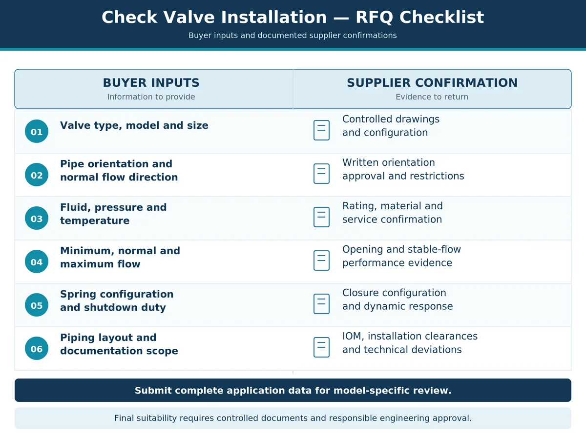
Normalize quotations against the same flow points, fluid properties, installation angle and shutdown conditions. Mark each supplier return Confirmed, Partial, Open or Not Applicable; an unresolved orientation, minimum-flow or trip-response requirement is a hold point, not an assumed pass. The Guida alla scelta delle valvole di ritegno covers wider construction screening, while the check valve datasheet requirements provide a focused framework for tag-level RFQ inputs. Request the proposed model’s actual drawing revision, spring option and technical-deviation list with the offer.
Final Installation Approval Checklist
Before authorizing installation, verify:
- Orientation approval: Pipe direction, flow direction and body position are permitted by exact-model controlled documentation.
- Closure mechanism: Gravity, spring assistance and closure travel have been reviewed for the supplied internal configuration.
- Operating stability: Minimum, normal and maximum flow agree with the valve’s documented opening characteristics.
- System response: Startup, shutdown and possible reversal have been assessed to a depth appropriate for their consequences.
- Installation documentation: Interfaces, access, inspection scope and deviations are resolved.
A valve should not be approved merely because the body fits the piping or a similar design has worked elsewhere. The decision is whether this specific configuration can be installed, open, operate stably and close as required in the actual service.
Request a Check Valve Installation Review
Selecting a check valve for a vertical line or demanding pump-discharge arrangement requires more than a generic valve-family recommendation. Submit the following application information for supplier screening and a model-specific technical discussion:
- Valve type, size, pressure class and end connection;
- Pipe orientation, flow direction and available installation drawings;
- Medium, operating pressure and temperature;
- Flusso minimo, normale e massimo;
- Pump or compressor start, stop and trip sequence;
- Available valve drawings or IOM, and spring configuration where known;
- Materials, leakage criteria, inspection, tests and documents required.
Submit Your Valve Datasheet / Request Installation Review
Ask the supplier to state which installation conditions are confirmed, which need a model-specific calculation or test, and which remain open technical deviations. Any Raymon Valve product-specific capability, approval, testing and document scope must be confirmed in the actual offer. Final suitability depends on the complete project data, controlled manufacturer documents, agreed specifications and responsible engineering approval.
Domande frequenti
Can a check valve be installed in a vertical pipeline?
Yes, some check valves can be used in vertical piping. Normal flow direction matters: vertical upward approval does not establish downward-flow approval. Review exact-model IOM, closure mechanism and spring requirements, then verify the actual flow and shutdown duty.
Can a swing check valve be installed with vertical upward flow?
Some swing checks permit upward flow in vertical piping, depending on hinge arrangement, disc movement and manufacturer approval. Flomatic’s 92LS provides a documented example with manufacturer consultation for vertical installation. That approval does not extend to all swing checks or downward flow.
Is vertical downward flow acceptable for a check valve?
Yes, but only for models explicitly approved for downward normal flow. A manufacturer’s clean-water, spring-assisted model may permit it while requiring a special spring for certain sizes. That approval does not transfer to other designs, sizes or fluids. Confirm the exact IOM, spring option, fluid limitations and operating range before approval.
Does a spring-loaded check valve work in any orientation?
No universal approval follows from the presence of a spring. Closure geometry, spring configuration, guide friction, differential pressure and flow still matter. Confirm each proposed orientation in the exact model’s approved drawing and IOM.
Which direction should the arrow on a check valve point?
The body arrow should point along normal forward process flow, not the reverse direction being prevented. That is necessary but not sufficient: permitted body rotation and vertical or inclined installation still require independent verification.
Why can a correctly oriented check valve still chatter?
Actual flow may be too low to hold the closure element stably open. Pulsation, disturbed inlet flow, spring behavior, deposits, friction or wear can also contribute. Review flow history, pressure data, piping arrangement and model-specific stable-opening guidance before assigning a cause.
What documents are required to approve check valve installation orientation?
Provide the exact model, size, controlled GA or sectional drawing, model-specific IOM, normal-flow arrow and proposed mounting orientation. Include spring-option identification and applicable minimum-flow and pressure-drop data. For pump-trip or high-consequence duty, add relevant closing-response evidence and project transient review. Record technical deviations and the responsible engineering sign-off.
Nota tecnica
Scopo: This article supports preliminary installation screening, technical coordination and RFQ preparation. It is not an installation authorization.
Presupposti e limiti: No Raymon Valve model-specific controlled drawing, performance calculation, test record or plant operating history was supplied for this guide. Manufacturer examples apply only to their documented products.
Confine di approvazione: Final installation permission and operating suitability require the exact valve configuration, project conditions, manufacturer instructions, applicable standards and responsible-engineer approval.
Evidence classification: Flomatic and Val-Matic provide third-party model examples; ASME references supply code and standard context; generated images are conceptual. None certifies a Raymon Valve product or replaces missing model-level IOM, stability or shutdown evidence.
Content responsibility: Raymon Valve Technical Content Team; no named licensed engineer or project reviewer is claimed.
 Italian
 English
 German
 Arabic
 French
 Spanish
 Portuguese
 Russian