
Technical Guide · Installation & Commissioning
Butterfly valve installation mistakes often result from mismatched flange bores, incorrect gasket dimensions, insufficient disc clearance, poor flange alignment or unverified dead-end pressure direction. These errors can cause disc interference, seat damage, external leakage, excessive operating torque and unsafe maintenance conditions. Before installation, engineers should compare the actual piping dimensions and pressure arrangement with the valve manufacturer’s approved drawings and installation instructions. Matching the nominal valve size and flange pressure class alone does not confirm installation compatibility.
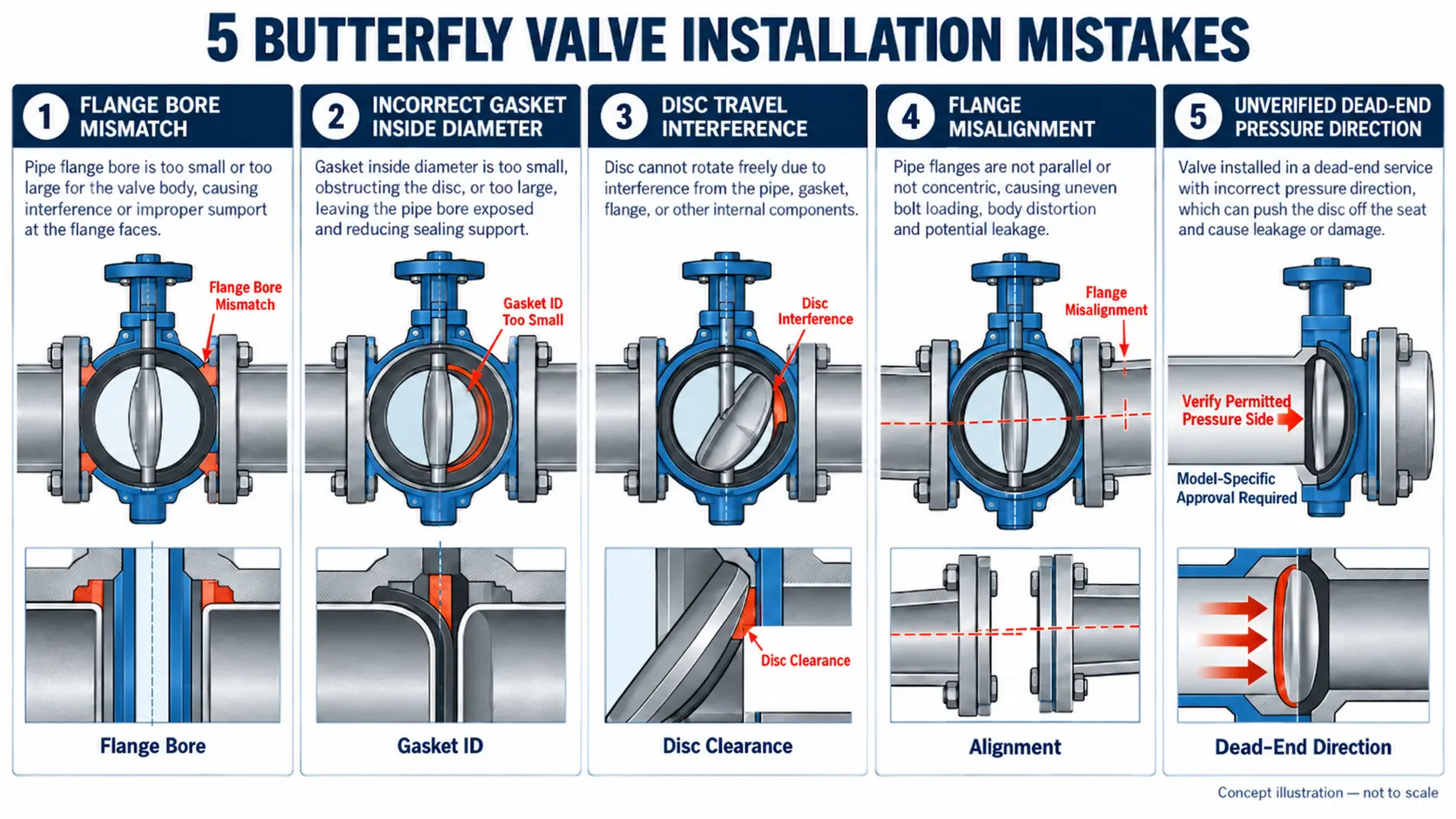
Quick answer: verify the installed interfaces, not only nominal size
For each valve tag, compare the measured flange bore and liner thickness with the approved GA drawing; verify whether the seat itself forms the flange seal; check the full disc sweep and pipe alignment; and confirm the exact dead-end pressure side, rating and downstream flange requirement. Record unresolved mismatches as hold points before final bolting or commissioning. Do not use actuator force, additional gaskets or bolt tightening to compensate for unapproved interfaces.
1. Five Butterfly Valve Installation Mistakes to Check Before Commissioning
A valve can satisfy its purchase specification and still perform poorly after installation if its interface with the piping was not checked. Butterfly valve discs rotate within the flow passage, and some designs project beyond the valve body’s face-to-face envelope during travel.
| Installation mistake | Potential consequence | Required verification |
|---|---|---|
| Incorrect flange bore | Disc interference or unsuitable sealing support | Actual effective bore and approved manufacturer limits |
| Incorrect gasket ID or arrangement | Disc obstruction, uneven compression or flange leakage | Gasket dimensions and model-specific sealing design |
| Insufficient disc clearance | Restricted rotation, damage or abnormal torque | Complete disc sweep envelope and adjacent geometry |
| Flange misalignment | Uneven compression, external leakage or mechanical contact | Parallelism, concentricity, pipe support and bolting method |
| Unverified dead-end arrangement | Unsupported pressure duty or unsafe maintenance assumptions | Pressure side, rated differential, bolting and manufacturer approval |
For available end connections and construction types, see Raymon Valve’s industrial butterfly valve range. A factory seat test alone cannot confirm compatibility with the actual piping geometry.
2. Mistake #1: Ignoring the Actual Flange Bore
Why nominal valve size does not guarantee bore compatibility
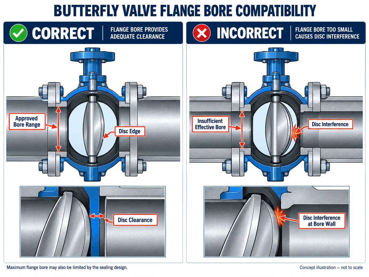
Two connections can share the same DN/NPS designation while having different effective openings. Pipe wall thickness, flange form, welding details and internal linings may reduce the space available for the rotating disc. In designs where the disc travels beyond the body faces, a smaller-than-expected bore can cause physical interference.
At the opposite extreme, a flange bore that is too large may reduce liner support or sealing contact in certain constructions. Manufacturer drawings may therefore specify a minimum, preferred and maximum mating bore. Treat these as model-specific interface limits, not nominal pipe-size tolerances that apply to all butterfly valves.
How to check minimum bore and disc sweep clearance
Compare the measured or approved piping interface with the exact valve drawing. Confirm the valve model, mating flange standard and facing, actual flange ID, pipe schedule, internal lining thickness, allowable bore range and disc projection at relevant positions.
Useful handover evidence: record the smallest effective opening at the actual flange and adjoining pipe, noting the influence of lining, weld intrusion or reducers. Compare it with the manufacturer’s allowable interface range and the drawing showing disc projection. A flange table alone does not establish the as-built clearance.
Illustrative fit-up scenario: A valve and spool match in NPS and bolt pattern, but a thick-wall spool with internal lining has a smaller effective opening at the flange neck. The check is not another nominal-size lookup: measure the as-built minimum bore, compare it with the approved disc projection and allowable bore range, and record a piping or valve revision if the interface fails. Do not machine or enlarge the flange bore without engineering approval.
When a reducer, liner or spacer needs additional review
A nearby reducer, pipe liner or transition piece may obstruct disc movement even where the nominal flange designation matches. A spacer or revised connection can be considered only after engineering review of dimensions, sealing interfaces, pressure rating, bolting and piping loads. Do not assume that a larger flange opening is always an acceptable solution.
3. Mistake #2: Using the Wrong Gasket ID or Gasket Arrangement
When the liner itself acts as the flange seal
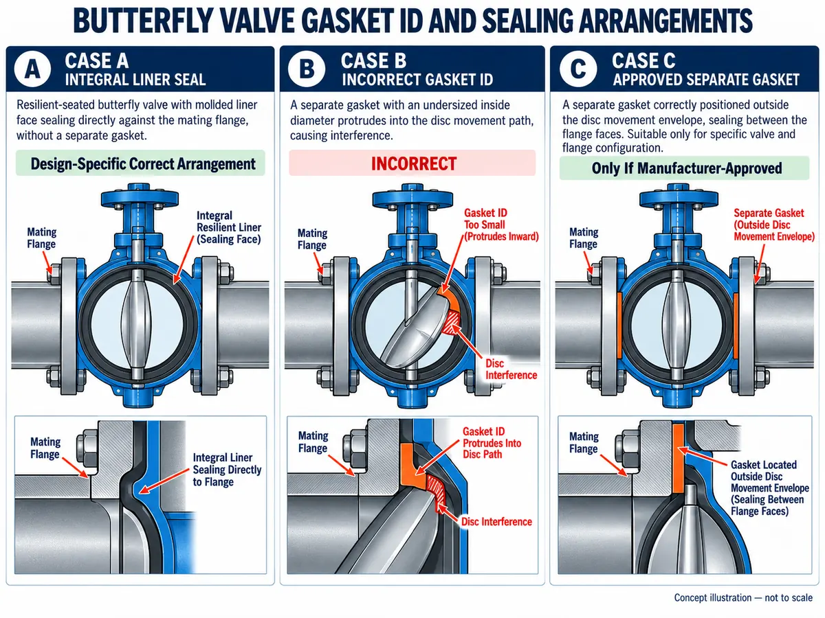
Many resilient-seated butterfly valves incorporate a molded liner or seat face that seals directly against the mating flange. For these specific constructions, installing an additional gasket may be unnecessary or may disturb the intended flange-sealing arrangement. The rule is design-specific, not universal.
How an incorrect gasket ID obstructs the disc
If a separate gasket is required or approved, an undersized inside diameter may extend into the disc travel envelope. An incorrectly centered gasket can do the same. Excessive thickness, unsuitable facing geometry or improper compression may also affect sealing loads.
For an approved separate gasket, confirm ID, outside sealing contact area, thickness, material, flange facing and pressure-temperature suitability. An ID that clears the disc does not by itself demonstrate sufficient gasket support or a compatible seal. If the valve liner forms the flange seal, do not apply separate-gasket assumptions.
Illustrative RFQ scenario: A quotation includes a separate flange gasket as a standard item, while the specified resilient liner is designed to seal directly against its mating flange. Before approving the bill of materials, check the exact model IOM and flange surface condition; either remove the unnecessary gasket from the agreed scope or document the manufacturer-approved gasket design and dimensions. A generic gasket schedule cannot settle this interface.
When a separate gasket may be required
For an example of model-specific requirements, Bray’s 2-Cx PTFE-lined butterfly valve IOM describes a liner that ordinarily serves as the flange gasket, with potential exceptions for limited flange strength or irregular flange surfaces. This guidance applies to that product, not to all PTFE-lined or resilient-seated valves.
4. Mistake #3: Failing to Verify Full Disc Clearance
Check the complete disc sweep envelope
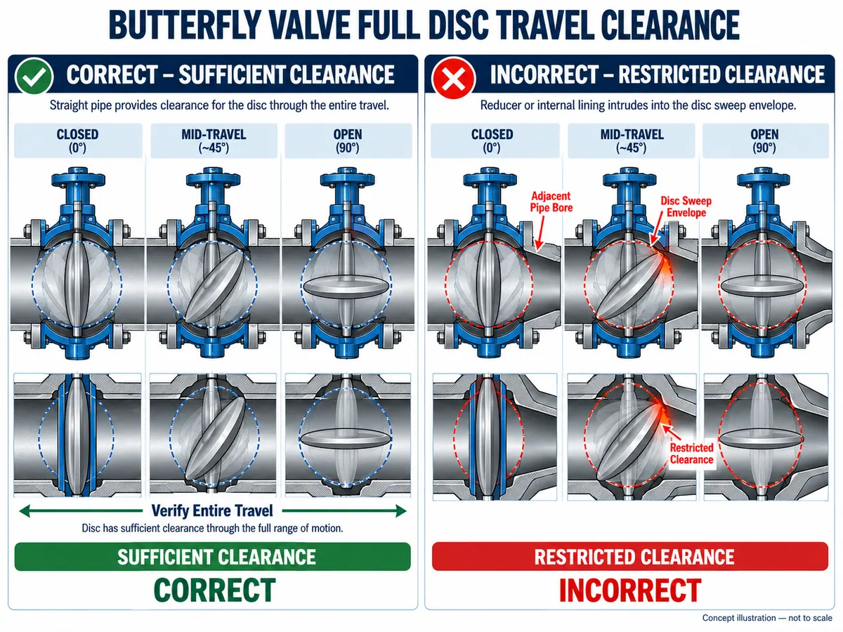
Flange bore and disc clearance are related but separate checks. Bore verification addresses the connecting opening; disc clearance addresses the entire volume occupied as the disc rotates through its permitted travel. A disc may clear one position and contact the adjoining pipe, gasket, lining or reducer in another.
Interference near reducers, linings and adjacent equipment
Compact piping layouts can position restrictions close enough for a disc to collide with them. The valve must therefore be reviewed together with its neighboring components. Successful insertion between the flanges does not establish adequate movement clearance.
The review should distinguish geometric clearance from actuator travel setting: limiting the stroke to avoid a collision is not an approved substitute for correcting an incompatible pipe or flange interface. Any revised travel limit must be separately justified against the required valve duty and manufacturer instructions.
Illustrative commissioning scenario: A valve moves freely before installation but develops unexpected resistance after flange bolting. The change points to an installed-interface or loading issue that needs investigation, but it does not by itself identify the cause. Stop the functional check, make the equipment safe under site procedures, compare the as-installed geometry and actuator setup with the approved records, and repeat the authorized test only after the cause is resolved.
Check movement without damaging the seat
The applicable IOM defines the disc position during insertion, centering and final bolting. Some manufacturers call for a partially open disc during installation, but the required position varies by design and actuation. After proper installation, qualified personnel should verify permitted travel under an approved and safe procedure.
If resistance or contact is detected, stop the movement. Do not increase actuator torque or override the stops to force the disc through an obstruction. Correct the root cause and repeat the specified functional verification.
5. Mistake #4: Forcing Misaligned Flanges Together
Flange parallelism and pipe centerline alignment
The valve body must not be used to correct misaligned piping. Offset pipe centerlines or nonparallel flange faces can place unintended loads on the assembly, disturb seat compression and shift the disc relative to the pipe bore.
Uneven flange loading and seat distortion
Depending on the construction, uneven flange loading can cause external leakage, liner distortion or abnormal opening and closing torque. The symptom is not conclusive by itself: mechanical interference, actuator setup and internal valve conditions may produce similar behavior.
Record the observed flange condition before tightening so later torque or leakage findings can be traced to the as-installed interface. Piping supports and loads are a piping-engineering responsibility and should be resolved before final valve joint acceptance.
Illustrative site scenario: A piping spool is pulled toward the valve using flange studs because its supports do not hold the flanges parallel. This may introduce uneven seat-face loading even if the bolt circle matches. Document the initial gap and offset, correct the pipe support/alignment under the piping engineer’s direction, and verify the seal and permitted valve movement against the approved installation criteria.
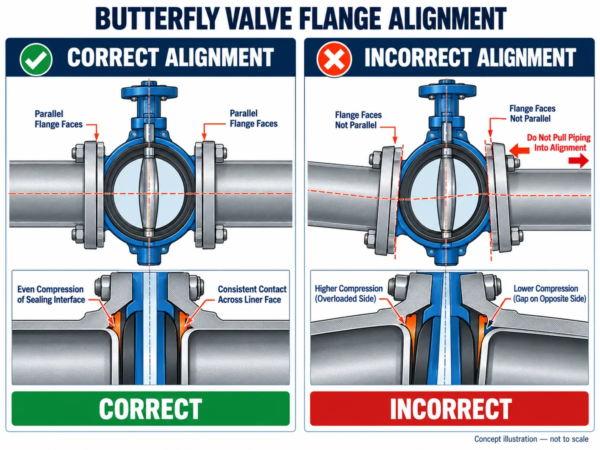
Correct alignment before final bolting
Check the approved criteria for parallelism, concentricity, flange separation, support and pipe loads. Inspect sealing faces and fasteners. Use the manufacturer- and project-approved bolt sequence and load requirements. Flange bolts should not be used to drag significantly misaligned pipes together.
6. Mistake #5: Assuming Any Lug Valve Can Handle Dead-End Service
What changes when the downstream flange is removed?
In a dead-end arrangement, one side of the closed valve may retain system pressure while the opposite pipe or flange is absent. This changes the pressure loading and support conditions for the body, seat and bolting. A lug body may support certain end-of-line applications, but body style alone does not establish its allowable dead-end rating.
Pressure direction is not necessarily flow direction
Normal process flow, maximum shutoff differential pressure and the actual source of pressure during maintenance can differ. A directional arrow must be interpreted using the model-specific IOM and marking instructions; it is not a general guarantee of allowable dead-end pressure direction.
RFQ distinction: state whether the downstream flange will remain installed during operation, be removed only after verified isolation, or be absent while one side may retain pressure. These are different configurations and should not share an assumed end-of-line rating.
Illustrative maintenance-planning scenario: A work package proposes removing the downstream spool while the upstream side may retain pressure because the valve body has lugs. That construction feature does not establish a safe isolation boundary or an allowable end-of-line differential pressure. Escalate the configuration for model-specific approval, confirm the pressure source and bolting requirement, and apply the facility’s independent isolation and zero-energy verification procedures before any dismantling work.
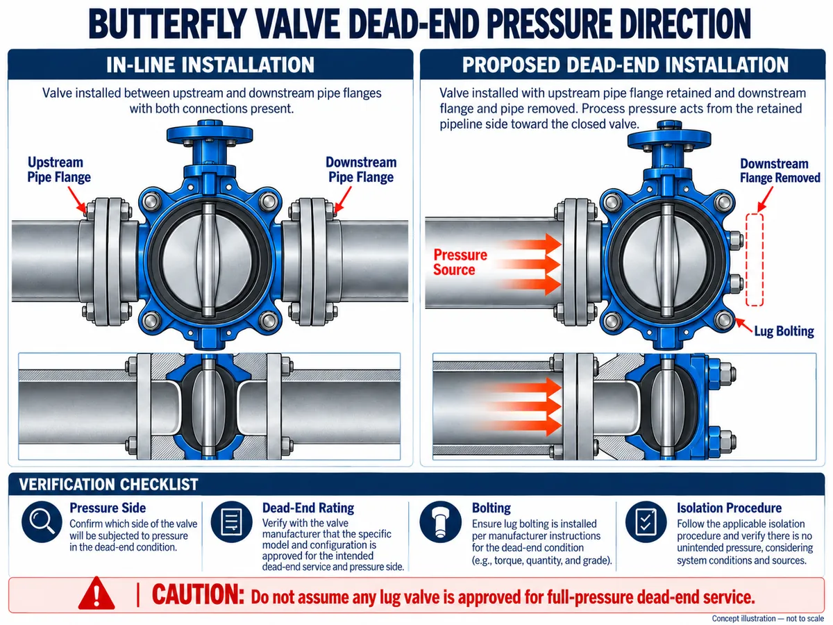
Full differential pressure versus reduced dead-end rating
Some valve designs have end-of-line limits different from their normal installed ratings. The allowable duty may depend on size, temperature, medium, actual pressure side, fastener arrangement and whether a counterflange remains. Confirm the exact configuration with manufacturer documentation; never infer full-pressure dead-end suitability from nominal pressure class or a bidirectional shutoff description.
Bolting, seat retention and manufacturer approval
For a proposed arrangement, request written confirmation of the permitted pressure side and magnitude, flange-removal condition, required fasteners and engagement, seat retention, and any applicable qualification evidence. See Raymon Valve’s Lug Butterfly Valve product information for the related construction and quotation scope; the actual end-of-line rating remains model-specific.
| Elemento di revisione | Question to resolve |
|---|---|
| Body and design | Is this exact model approved for the proposed end-of-line arrangement? |
| Pressure direction | Which side can be pressurized, and at what differential pressure? |
| Temperature and medium | Do the conditions change the allowable rating? |
| Counterflange | May the downstream flange be absent under the stated duty? |
| Fasteners and seat retention | What lug engagement, bolting and seat-retention limits apply? |
| Maintenance controls | What independent isolation, depressurization and verification procedures apply? |
7. Butterfly Valve Installation Troubleshooting: Symptoms, Causes and Checks
The same symptom can result from multiple faults. A torque increase, for instance, may be caused by disc contact, liner compression, actuator settings or service loads. Use evidence rather than assumptions to establish the cause.
| Observed symptom | Possible cause | Evidence to inspect | Direzione correttiva | Accettazione |
|---|---|---|---|---|
| Disc cannot fully open | Flange or adjacent-pipe interference | Actual bore, GA drawing, travel envelope | Correct the interference after safe isolation and review | Unobstructed approved travel |
| Excessive operating torque | Distorted seat, flange loading or mechanical contact | Alignment, IOM, baseline torque and actuator setup | Identify root cause; do not increase force blindly | Torque within documented limits |
| External flange leakage | Incorrect gasket, damaged face or uneven compression | Gasket/IOM, flange faces, tightening record | Restore approved sealing arrangement | Specified leakage criteria met |
| Closed-valve leakage | Seat damage, debris or pressure-direction issue | Test direction, seat and disc inspection, operating conditions | Validate cause and repair or replace as approved | Required seat-test acceptance |
| Damage after cycling | Disc interference or improper installation sequence | Pipe geometry and controlled inspection | Remove cause and evaluate damage | Inspection and functional acceptance |
| Dead-end leakage | Unsupported direction or pressure condition | Rating, IOM, configuration and actual pressure side | Suspend use pending engineering approval | Confirmed rating and safe arrangement |
Field evidence to preserve: photograph the connection and valve tag where permitted, record as-found flange and gasket dimensions, note the exact stroke position at which resistance appears, and retain the actuator or manual operating observations. Do not change stops or dismantle the joint merely to create a baseline. All physical inspection must follow the site safety procedure.
When commissioning should stop
Stop and escalate when mechanical contact, unexpected torque, unresolved leakage, suspected disc/seat damage or unverified dead-end conditions exist. Neither changing the actuator stops nor exceeding approved bolting requirements is an acceptable improvised fix.
8. Pre-Installation and Commissioning Checklist
The project inspection and test plan (ITP) should identify required evidence, witnesses and sign-off points. The checklist below is a planning framework, not a substitute for the approved site procedure.
Before positioning the valve
- Identify the valve tag, model, size, rating and drawing revision.
- Confirm flange standard, facing, effective bore and pipe schedule.
- Check internal linings and adjacent restrictions.
- Verify the approved gasket or liner-face sealing arrangement.
- Inspect the flange faces, disc and seat for contamination or damage.
- Review orientation and any actuator-handling requirements.
Before final flange tightening
- Confirm pipe centerline and flange-face alignment.
- Check flange separation and proper pipe support.
- Use the approved bolts and tightening instructions.
- Position the disc as directed by the specific IOM.
- Confirm disc clearance without applying excessive force.
- Check for unintended seat or liner displacement.
Before commissioning and pressure testing
- Complete the approved functional and travel checks.
- Confirm actuator stops and operation where applicable.
- Verify differential-pressure direction and dead-end restrictions.
- Complete specified pressure or leakage tests under approved limits.
- Record deviations and corrective actions.
- Obtain required engineering and inspection sign-off.
Hold-point evidence and sign-off
The following is a suggested responsibility and evidence split for project planning; the approved ITP and site procedures determine the actual signatories and hold points.
| Proposed hold point | Evidence to record | Typical reviewer / release decision |
|---|---|---|
| Before installation | Approved valve drawing and IOM revision; verified flange bore, pipe lining and gasket arrangement | Piping / mechanical engineering: interface accepted or held |
| Before final tightening | As-found alignment, support and approved fastening method; inspected sealing faces | Construction QA / responsible installer: joint ready or held |
| Before functional movement | Safe system status, travel envelope, actuator condition and approved test method | Commissioning team: proceed under procedure or stop |
| Before process service | Required travel, leakage or pressure test records, resolved deviations and end-of-line confirmation where applicable | Project-authorized sign-off under the ITP |
Do not interchange tests: a functional stroke check addresses movement; a specified seat-leakage test addresses shutoff under its test conditions; and flange-joint acceptance addresses the installed external pressure boundary. None independently establishes safe downstream maintenance isolation or a model-specific dead-end rating.
9. What Drawings and Documents Should Buyers Request?
Installation errors can be avoided before shipment by making the mechanical interfaces part of the RFQ. Quoting from DN/NPS, pressure class and material alone leaves important geometric and sealing questions open.
Valve GA drawing and disc-clearance dimensions
Request the face-to-face dimension, body interface, disc projection at relevant positions, allowed mating flange bore range and any necessary installation clearance.
Mating flange and gasket specifications
Provide the actual flange standard, facing, bore and lining. Require written identification of the permitted gasket type, ID and thickness or explicit confirmation that a separate gasket must not be used.
Installation instructions and dead-end evidence
Specify the model-specific IOM and, where applicable, written confirmation of end-of-line rating, pressure direction, bolting and downstream flange conditions. Document any supplier deviation instead of relying on an assumption.
| Document or record | Scopo |
|---|---|
| Approved valve datasheet | Tag-specific function and service conditions |
| GA and dimensional drawing | Face-to-face, disc projection and allowed flange interface |
| Flange, pipe and gasket drawings | Actual mating geometry and seal arrangement |
| Manufacturer IOM | Installation sequence, restrictions, applicable valve model/series, manual revision and issue date |
| Dead-end rating statement | Approved differential pressure, direction and configuration |
| ITP and commissioning record | Hold points, acceptance criteria and sign-off evidence |
RFQ interface data matrix: what to send and what to request back
Use the same field definitions for all bidders. Mark missing values as to be confirmed; do not let each supplier assume a different pipe bore or end-of-line condition.
| RFQ field supplied by buyer | Supplier response / evidence requested | Perché è importante |
|---|---|---|
| Valve tag, duty and DN/NPS | Exact offered model and approved drawing revision | Links the review to the delivered construction |
| Flange standard, rating, facing and actual bore | Permitted mating bore range and interface confirmation | Checks sealing support and disc clearance |
| Pipe schedule, internal lining and nearby reducer geometry | Disc projection / full travel envelope and any required separation | Identifies interference outside valve body faces |
| Proposed gasket ID, material, thickness and face condition | Approved sealing arrangement or explicit no-separate-gasket instruction | Prevents gasket intrusion and unsuitable clamping |
| Operating method, actuator and required travel | Model-specific IOM, limits and functional test requirements | Avoids treating excessive force as a correction |
| Design pressure, temperature, medium and possible reverse differential | Applicable pressure-temperature / directional limitations | Separates normal flow from possible pressure sources |
| Downstream flange configuration and removal condition, if any | Written end-of-line rating and bolting / seat-retention restrictions for that exact configuration | Prevents unverified dead-end assumptions |
| Project ITP, witness and documentation requirements | Required drawings, test scope, inspection records and deviation schedule | Allows like-for-like technical bid review |
How to control installation-related technical deviations
If a supplier proposes a spacer, different flange interface, alternative gasket or reduced dead-end rating, request a written deviation that identifies the affected valve tags, revised drawing, installation consequence and required engineering approval. Record acceptance before procurement release or site alteration; a quotation footnote is not an approved field modification.
For broader construction and service screening, consult the Guida alla selezione delle valvole a farfalla.
10. Which Standards and Manufacturer Instructions Apply?
API 609: butterfly valve product requirements
API 609 covers specified butterfly valve product constructions. API announced publication of its 10th edition in 2026, with a December 1, 2026 effective date identified for the API Monogram program. The governing edition for a particular order must be established from its contract and applicable requirements. The standard does not independently prove the suitability of a particular flange bore or dead-end arrangement.
ASME B16.5: mating flange requirements
ASME B16.5-2025 addresses specified pipe flanges and flanged fittings, including dimensions, tolerances, materials and pressure-temperature ratings. Matching an applicable flange standard is necessary for the specified interface but is not proof of full disc clearance or correct gasket installation.
Why the approved manufacturer IOM still matters
The applicable IOM supplies model-specific bore ranges, sealing arrangements, disc position during installation, bolting guidance and end-of-line restrictions. Even similar-looking lined valves may have different installation requirements. Use the IOM, approved drawings and project standards together rather than assuming that one document replaces the others.
Manual version and scope check: Record the manufacturer, exact valve series/model, manual revision or issue date and corresponding drawing revision for each valve tag. The linked Bray 2-Cx IOM is an example for that named PTFE-lined product; AVK’s Series 820 product page lists an installation manual named 820_MI_revE 2026.pdf. Confirm the currently applicable revision before using either document. Neither manual establishes allowable dimensions or dead-end ratings for a different valve.
Confine delle prove: A valve factory shell or closure test demonstrates only the specified pressure-boundary or seat-leakage acceptance under the test conditions. It does not validate the installed flange joint, full disc sweep, external pipe loading or personnel isolation. Record separate acceptance criteria for dimensional fit-up, functional stroke and in-situ testing, and ensure the project test procedure does not exceed the valve’s approved limitations.
For the wider standards context, see Raymon Valve’s industrial valve standards resource. These sources do not certify the configuration of a different manufacturer’s valve.
11. Frequently Asked Questions
Can a butterfly valve be installed if the flange bore is smaller than the nominal valve size?
Not automatically. The actual effective opening must satisfy the specific valve’s approved minimum and maximum interface dimensions. Verify the as-built bore, sealing support and disc travel envelope before acceptance.
Do all butterfly valves require separate flange gaskets?
No. Some designs use an integral liner or seat face to seal against the flange. Other designs or flange conditions may require or permit a separate gasket. Follow the exact model’s approved IOM and connection specification.
How do you check butterfly valve disc clearance before commissioning?
Compare the full permitted disc sweep envelope against the real flange, pipe, lining, reducer and nearby equipment geometry. Qualified personnel should carry out the approved functional check under safe conditions and document any abnormal resistance.
Can flange misalignment cause excessive operating torque?
Yes. Uneven seat loading or an offset disc-to-pipe relationship can contribute to high torque. However, actuator settings, service pressure and internal mechanical conditions also require investigation.
Can a lug butterfly valve be used for dead-end service without a downstream flange?
Only if the exact valve model and configuration are approved for that arrangement. Confirm pressure side, allowable differential pressure, temperature, fasteners and any downstream flange requirements with the manufacturer.
Does a flow direction arrow indicate the allowable pressure direction?
Not necessarily. Its meaning may relate to normal flow, preferred orientation or a pressure-direction limit. Interpret the marking according to the approved IOM and model-specific ratings.
Which documents are needed before butterfly valve installation?
At minimum, review the approved valve datasheet and GA drawing, mating flange and piping details, applicable gasket specification and the manufacturer’s IOM. Add dead-end rating evidence, ITP hold points and commissioning records as required by the project.
12. Conclusion: Verify the Installation Interface Before Commissioning
Preventing butterfly valve installation mistakes requires checks beyond nominal size and pressure class. Actual flange bore, gasket arrangement, complete disc travel, flange alignment and pressure direction should be evaluated as a connected installation system. The correct result comes from approved project drawings, the actual as-built interfaces, the manufacturer IOM and documented inspection requirements.
Where information is incomplete, request clarification before the valve is installed or commissioned rather than attempting to compensate in the field.
Request a Butterfly Valve Installation Compatibility Review
Preparing an RFQ or checking a proposed installation? Send the valve tag and drawings together with the measured pipe and flange interfaces. Identify any unknowns rather than inserting assumed dimensions. Ask for a model-specific compatibility response, drawing revisions and an explicit technical-deviation list before project approval.
- Valve tag, duty, exact model or required construction
- DN/NPS, pressure class/PN and mating flange standard
- Actual flange ID, pipe schedule, lining and nearby fittings
- Gasket ID, thickness, material and flange facing
- Valve GA, piping drawings and available IOM revision
- Medium, design pressure/temperature and possible pressure reversal
- Actuator type, required travel and observed operating issue (if any)
- Dead-end configuration, pressure side and downstream flange status
- Inspection hold points, testing scope and required evidence
Technical acceptance is subject to project documentation, approved manufacturer requirements and responsible engineering review.
 Italian
 English
 German
 Arabic
 French
 Spanish
 Portuguese
 Russian