
An ESD valve is assigned a defined emergency shutdown duty, while a standard on-off valve normally provides operational isolation. The same valve design may be used in either application, but ESD suitability depends on the complete safety function: required safe state, actuator fail action, response time, SIS interface, testing and supporting evidence. For EPC engineers and buyers, the key task is to specify and compare the complete package—not just the valve body or actuator.
This distinction affects the valve datasheet, actuator sizing basis, solenoid and feedback arrangement, FAT scope and supplier documentation. A valve with an open/close actuator is not automatically suitable for an ESD duty; the project safety requirements and verification evidence determine whether the assembly is appropriate.
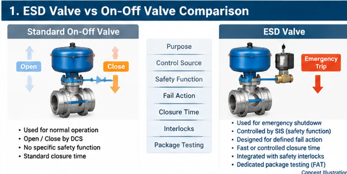
1. What Is the Difference Between an ESD Valve and an On-Off Valve?
The main difference is the required function, not necessarily the mechanical construction.
An on-off valve is designed to provide two principal operating positions: fully open and fully closed. It is commonly used for process isolation, equipment switching, line-up operations and other routine plant functions.
An ESD valve, or Emergency Shutdown Valve, is assigned a specific emergency isolation function. When defined shutdown conditions occur, the valve must respond according to the approved safety requirements and move toward its specified safe position.
Both applications may use pneumatic, electric or hydraulic actuators. Valvole a sfera e valvole a farfalla are common candidates for automated isolation duties, depending on process conditions and project specifications. For the broader project-engineering framework—including process inputs, package interfaces and requirement-to-evidence planning—see Raymon Valve’s Emergency Shutdown Valves engineering solution guide.
However, a valve does not become an ESD valve simply because it has an actuator, a solenoid valve or an open/close command. The distinction is whether the complete valve assembly has been selected, integrated, specified and verified for its assigned safety function.
Typical RFQ mistake: a buyer specifies only “pneumatic on-off valve, fail close” and assumes this is a complete ESD requirement. The cause is an incomplete duty definition: the trip source, failure scenarios, required response time and test evidence have not been stated. Prevent this by issuing the relevant SRS or cause-and-effect requirements and asking the supplier to identify assumptions and deviations before quotation.
Three Different Engineering Concepts
- On-off operation: The valve receives a command to open or close.
- Emergency shutdown duty: The valve must perform a defined isolation action following an emergency condition.
- Safety instrumented function (SIF): The complete safety function operates through the required sensors, logic solver and final element to achieve a specified risk-reduction objective.
An ESD valve may therefore be an actuated on-off valve, but a standard on-off valve is not automatically suitable for an ESD application.
2. ESD Valve vs On-Off Valve: Side-by-Side Comparison
The following table summarizes the differences that matter during engineering review and procurement.
| Elemento di confronto | ESD Valve | Standard On-Off Valve |
|---|---|---|
| Primary purpose | Emergency shutdown or safety-related isolation | Routine operational isolation |
| Operating requirement | Defined emergency response | Normal open/close operation |
| Safety function | May serve as the final element of a SIF | Not inherently assigned a SIF |
| Azione di fail | Defined by the safety requirements | Defined by operational requirements |
| Closure time | Project-specific shutdown response requirement | Process operating requirement |
| Control interface | Safety-related trip interface where specified | Standard control or operating interface |
| Interlocks | Part of the defined shutdown logic where applicable | Operational permissives and interlocks |
| Feedback di posizione | Required according to the safety and control design | Based on operational requirements |
| Collaudi | Functional and proof-test requirements as specified | Routine functional inspection and testing |
| Documentazione | Safety-function and package-related evidence | Standard product and package documentation |
The most important distinction is that the ESD application introduces additional requirements for the complete safety function. The valve body itself may be mechanically similar to one used in a normal isolation application. Nevertheless, the actuator, stored-energy arrangement, solenoid, accessories, feedback devices, installation and testing requirements may differ considerably.
3. Safety Function: What Makes an ESD Valve Different?
Emergency Shutdown vs Normal Process Isolation
A standard on-off valve normally responds to an operator command or process control instruction. For example, an operator may close an automated valve to isolate a pump, storage vessel or process line during routine maintenance or equipment switching.
An ESD valve performs a different duty. It is assigned an action that forms part of an emergency response strategy. A shutdown demand may originate from conditions such as:
- High-pressure or low-pressure trip conditions.
- High-temperature process conditions.
- Fire and gas detection.
- Equipment protection requirements.
- Emergency stop commands.
- Other conditions defined in the approved cause-and-effect documentation.
The actual trip conditions must be established through the project safety design. They should not be assumed from a generic valve specification.
Engineering review example: a high-pressure trip may require isolation of an incoming feed, while another process scenario may require a different valve to remain open to preserve cooling or depressurization. The hazard analysis and approved cause-and-effect logic determine the required action; selecting “fail close” by habit can create a different process risk.
The Role of the Final Element in an SIS
A Safety Instrumented System generally includes three functional elements:
- Sensors that detect abnormal process conditions.
- A logic solver that evaluates the safety demand and initiates the required action.
- Final elements that perform the physical action required to achieve the safe state.
An ESD valve may form part of the final element assembly. Depending on the design, this assembly can include the valve body and internal components, a pneumatic/electric/hydraulic actuator, solenoid valve, position feedback switches, pneumatic accessories and tubing, and local control or indication devices where specified.
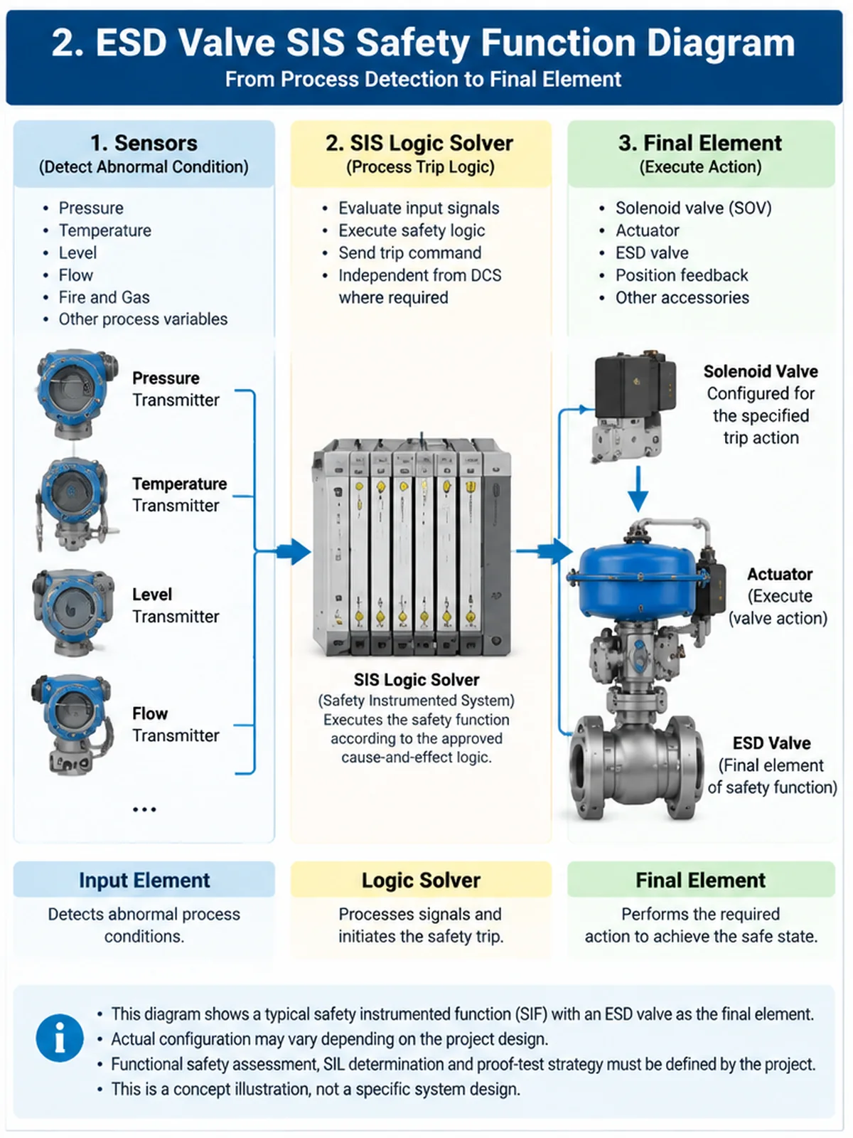
The complete arrangement must be considered when evaluating the safety function. A valve with a suitable mechanical design may still be unsuitable for a particular ESD duty if the actuator, accessories, interface or testing arrangements cannot meet the project requirements.
SIL Requirements and Package Responsibility
Safety Integrity Level (SIL) relates to the required risk-reduction performance of a safety instrumented function. It should not be treated as a simple product classification.
A valve, actuator or solenoid may have relevant functional-safety documentation, but this does not automatically establish that the complete safety instrumented function meets its required SIL. The engineering assessment must consider the complete safety loop, including:
- Sensor subsystem.
- Logic solver.
- Final element subsystem.
- Failure data and diagnostic coverage.
- Proof-test interval and proof-test coverage.
- Common-cause failure considerations.
- Hardware and systematic capability requirements.
For procurement, the buyer should identify the required safety function and ask the supplier to provide the applicable product and subsystem evidence. Final SIL verification remains part of the responsible functional-safety engineering process.
4. Fail Action: Fail Close, Fail Open or Fail in Place?
Fail action must be defined against a specific failure scenario. “Loss of air,” “loss of electrical power,” “loss of hydraulic pressure” and “loss of the control signal” are not interchangeable conditions. A package may respond differently to each event unless the actuator and accessory arrangement is specifically designed to produce the same result.
For an ESD application, the specification should identify the failure being considered, the required valve position, the energy source used to complete the stroke, and the conditions under which that response must be achieved. Do not write only “fail safe” without defining the actual action.
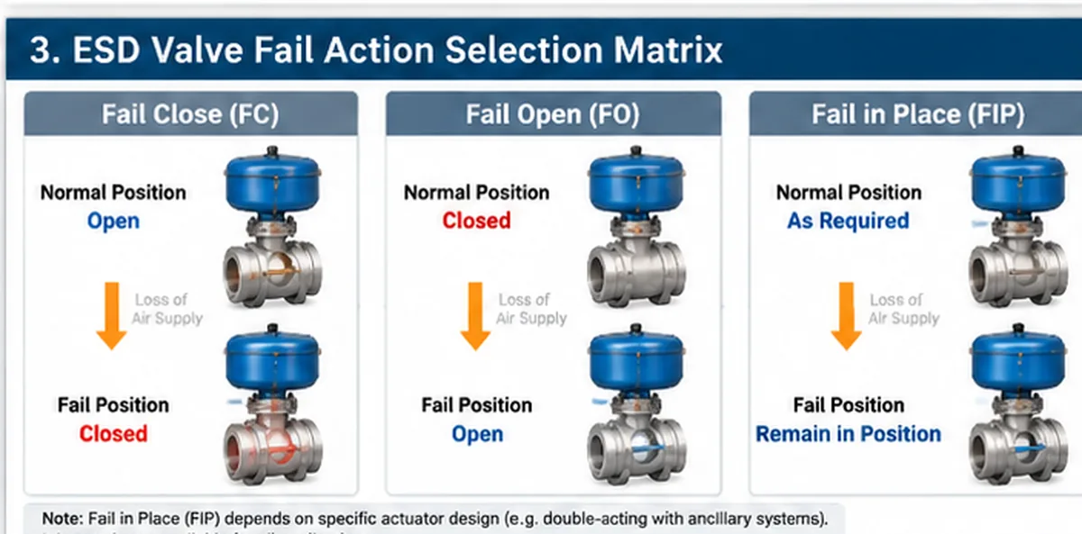
Fail Close (FC)
A fail-close arrangement is designed to drive the valve toward its closed position following the specified loss-of-energy or control condition. It may be selected where stopping process flow is required to establish the defined safe state.
Engineering considerations include process isolation requirements, upstream and downstream pressure, potential trapped pressure, actuator spring-return or stored-energy capacity, and required closing torque throughout the valve stroke.
Fail Open (FO)
A fail-open arrangement is designed to drive the valve toward its open position under the specified failure condition. This may be required when maintaining flow or preventing another process hazard is part of the approved safety strategy.
Fail open should not be considered inherently less safe than fail close. The appropriate position depends on the consequences of each possible process response.
Fail in Place (FIP)
A fail-in-place arrangement attempts to retain the existing valve position following a specifically defined failure condition. It is not an inherent behavior of every actuator and may require a purpose-designed locking, accumulator or control arrangement, depending on the actuator technology and failure being considered.
Fail-in-place behavior must be explicitly engineered and verified for the defined failure condition. It should not be assumed to provide the same emergency shutdown response as a stored-energy fail-safe arrangement. The specification must state whether the requirement applies to loss of instrument air, electrical power, hydraulic supply, control signal or another event.
What Determines the Required Fail Position?
| Elemento di revisione | Engineering Question |
|---|---|
| Hazard analysis | Which valve position helps establish the defined safe state? |
| Process flow | What happens if flow stops or continues? |
| Medio | Does the process fluid introduce additional hazards? |
| Pressure conditions | Could isolation create trapped pressure or another hazard? |
| Aria strumentale | What happens when the air supply is lost? |
| Electrical power | What happens when electrical power is interrupted? |
| Hydraulic supply | Is sufficient stored energy available for the required stroke? |
| Actuator arrangement | Does the actual configuration provide the specified response? |
The fail action must be defined in the project safety requirements and confirmed against the complete operating and failure scenarios.
Specify the Failure Scenario, Not Just the Fail Position
| Failure Scenario | What Must Be Defined | Package Verification |
|---|---|---|
| Loss of instrument air | Whether stored energy drives the valve to the required position and the minimum available supply condition before failure | Simulate the specified air-loss condition and record final position and response time |
| Loss of electrical power | Whether the solenoid, actuator accessories and feedback devices de-energize or retain their state as designed | Verify the specified electrical failure response and status indication |
| Loss of control signal | Signal-failure behavior, including energized/de-energized trip philosophy where applicable | Simulate the agreed signal fault at the defined interface |
| Loss of hydraulic supply | Available stored hydraulic energy and the required response for the selected actuator | Verify the specified hydraulic failure condition using the approved test procedure |
| Loss of position feedback | Alarm, diagnostic or degraded-state behavior; feedback loss is not automatically the same as loss of actuation energy | Check the agreed alarm and control-system response |
This matrix is a specification aid, not a universal cause-and-effect chart. The approved SRS, cause-and-effect matrix and actuator design determine which scenarios must be tested.
5. Closure Time: Why Faster Is Not Always Safer
Closure time is one of the most important differences between a routine on-off application and an emergency shutdown application. For an ESD valve, the required response time may be established by process safety studies, shutdown sequence requirements and hydraulic or process transient analysis.
What Is ESD Valve Closure Time?
Closure time is the time required for the valve to travel from its initial specified position to its required final position following the defined command or trip condition. The specification should clarify the measurement boundaries.
For example, the project may require consideration of the time from the initiating trip signal to solenoid response, the time required for the actuator to begin moving, total valve travel time, or the time from the trip signal to confirmed closed-position feedback. These are not necessarily the same measurement.
Factors Affecting Valve Stroke Time
- Valve construction and size: Valve type, size, pressure differential, internal design and operating torque influence actuator requirements.
- Actuator characteristics: Actuator output, spring characteristics, available air pressure, hydraulic supply and mechanical configuration affect the movement profile.
- Accessories: Solenoid valves, tubing, fittings, pneumatic restrictions and other accessories can influence total response time.
- Process conditions: Differential pressure, medium properties, pipeline configuration and operating conditions may affect required performance.
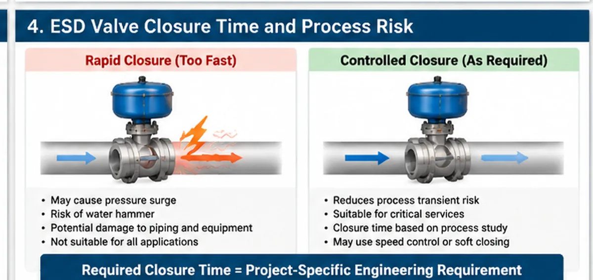
Fast Closure vs Pressure Surge Risk
A shorter closing time is not automatically better. Rapid valve closure can generate pressure transients, including surge conditions in liquid systems. Depending on the process and piping configuration, these effects may create additional mechanical and operational risks.
Conversely, excessively slow closure may fail to satisfy the required shutdown response. The engineering objective is to establish an acceptable response time that satisfies the safety requirements while accounting for process dynamics.
The final requirement should be supported by relevant engineering analysis rather than an arbitrary universal closing-time value.
Relate Valve Travel Time to Process Safety Time
Process Safety Time is the available time between the development of a potentially hazardous condition and the point at which that condition could lead to a hazardous event. The required Safety Instrumented Function response time must be short enough to achieve the defined safe state within the available process safety time, with the project-required margin.
The complete response chain can include sensor response, input processing, logic-solver execution, output response, solenoid operation, actuator movement and valve travel. Therefore, valve travel time alone does not establish that the SIF meets its response-time requirement. The project Safety Requirements Specification (SRS) should define the required response time and the assumptions used to allocate time across the SIF elements.
For further technical context, see the IET technical session on SIF response-time calculations, which discusses assessing the complete SIF response against process safety time.
How to Specify and Verify Closure Time
An ESD valve datasheet or package specification should identify:
- Required valve travel time.
- Measurement start and end points.
- Initial and final valve positions.
- Minimum and maximum operating supply conditions.
- Differential pressure and relevant test conditions.
- Required feedback signals.
- Acceptance criteria and recording method.
Actual closure time should be measured and documented during the agreed functional or package test. A supplier quotation should distinguish between an estimated actuator stroke time and a verified package response time.
Closure-Time Acceptance: Agree the Test Boundary Before Quotation
Two suppliers can quote different “closing times” while measuring different events. To make quotations comparable, define the timing boundary and test conditions in the datasheet or ITP.
| Acceptance Item | What the Specification Should State |
|---|---|
| Start event | Trip command at the package terminal, solenoid de-energization, or another agreed signal point |
| End event | Mechanical end of travel, closed limit-switch transition, or confirmed process isolation indication |
| Initial condition | Starting valve position and actuator condition |
| Process condition | Test differential pressure, flow condition if applicable, and relevant medium or simulation method |
| Energy condition | Specified instrument-air/hydraulic pressure or electrical supply, including minimum design condition where required |
| Temperatura | Ambient or specified operating temperature range for the test |
| Repeatability | Number of strokes and treatment of variation between recorded results |
| Acceptance record | Measured time, test conditions, instrument identification and pass/fail criteria |
Do not assume a no-load bench stroke time represents the installed valve response at the project differential pressure. The purchaser and supplier should agree whether the test demonstrates actuator travel time, complete package response time or the full trip-to-confirmation time.
Common field-review issue: a supplier reports a fast actuator stroke time, but the project acceptance criterion starts at the SIS trip output and ends at confirmed valve position. The mismatch occurs because the quoted and required timing boundaries are different. Resolve it by defining the start signal, end indication, utility condition, differential pressure and measurement method in the datasheet and FAT procedure.
6. Interlocks: DCS Commands vs SIS Trip Logic
The control interface is another important area where ESD and standard on-off applications differ.
DCS On-Off Commands
A standard on-off valve may receive open and close commands from a Distributed Control System (DCS), local control station or another operational control arrangement. The control system may also apply permissives and operational interlocks. These functions are designed around normal plant operation and equipment protection.
SIS Emergency Shutdown Commands
An ESD valve assigned to a Safety Instrumented Function may receive a trip command through the SIS. The safety logic is defined by the approved safety requirements and cause-and-effect documentation.
The ESD action should not be confused with an ordinary DCS operating command. The required separation, independence, shared devices, communication paths and interfaces between DCS and SIS must follow the project functional-safety design and applicable requirements. Do not assume every project uses an identical wiring or feedback arrangement.
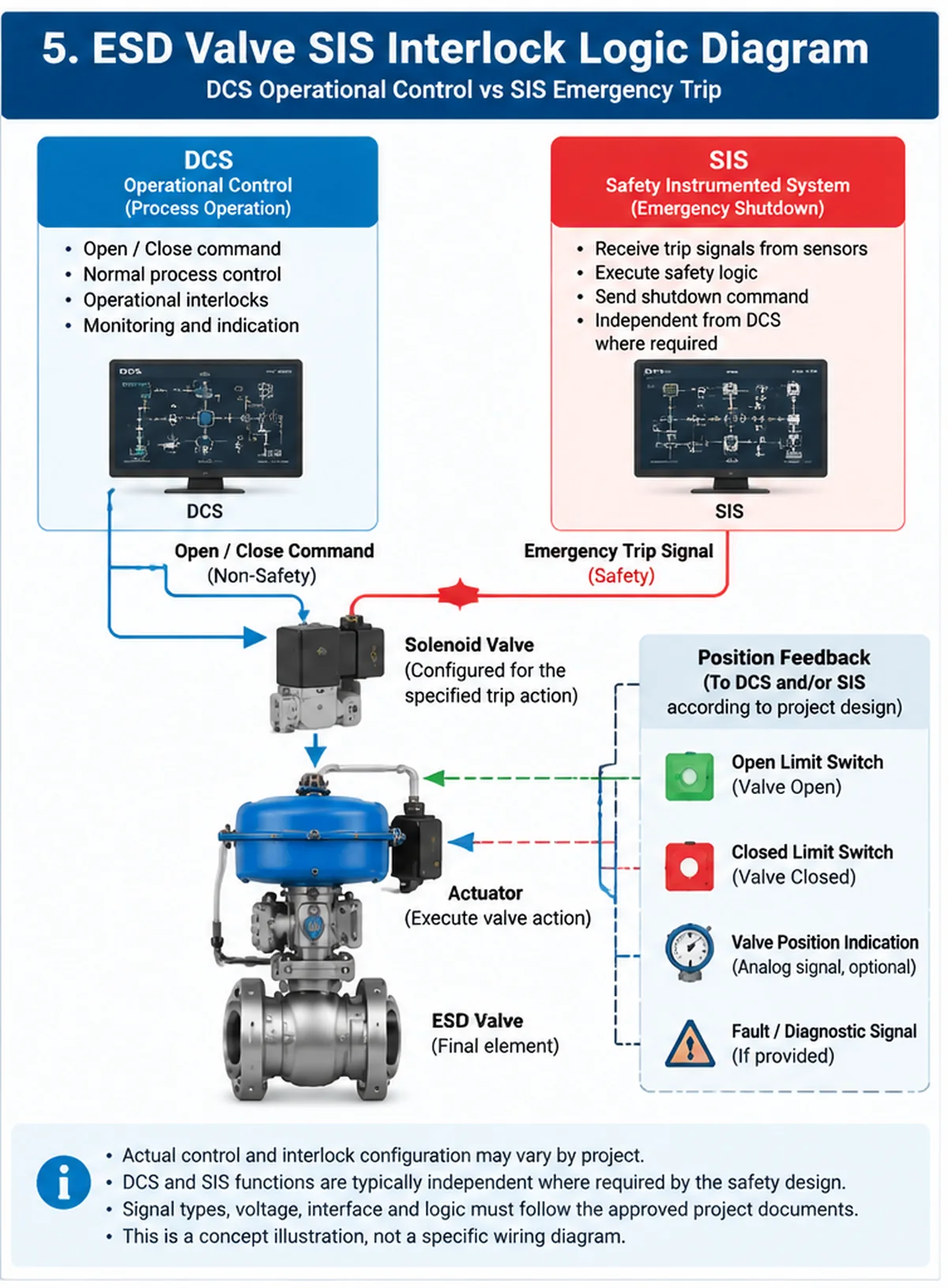
Solenoid Valve and Actuator Interface
For many pneumatic ESD packages, a solenoid valve provides the interface between the control signal and the actuator’s pneumatic circuit. The actual arrangement depends on the selected actuator and required fail action.
For a complete valve-and-actuator assembly, review the available integrated valve actuator package configuration alongside the project interface requirements. The product page provides the relevant package context; the final configuration must still be confirmed against the approved datasheet and project documents.
The package specification should identify:
- Solenoid valve type and operating principle.
- Energized and de-energized states.
- Electrical supply requirements.
- Air supply conditions.
- Pneumatic connections.
- Required response following loss of power or control signal.
The buyer should not assume that all solenoid configurations produce the same fail action.
Package Interface Review: Questions for the Supplier
- Which device receives the SIS trip signal, and at which terminal or interface?
- What is the solenoid’s specified energized and de-energized state?
- What happens after loss of power, air, hydraulic pressure or control signal?
- Are DCS operating commands and SIS trip functions separated as required by the approved design?
- Which open/closed feedback contacts are provided, and where are they wired?
- Are feedback contacts used for indication only, or are they part of a defined safety function?
- What happens if the valve fails to reach the commanded position within the specified time?
These questions should be resolved against approved wiring diagrams, loop diagrams, I/O lists and the cause-and-effect documentation before FAT.
Integration check: if a package passes a local solenoid test but the field loop is wired to the wrong input or feedback terminal, the local test alone will not reveal the complete interface error. Confirm terminal plans, loop drawings, I/O assignments and the agreed end-to-end test boundary before dispatch or site commissioning.
Position Feedback and Alarm Signals
Position feedback allows the control system to monitor valve status. Typical signals include open limit switch, closed limit switch, valve position indication and actuator or accessory fault indication where provided.
The project should define whether feedback is required for normal operation, shutdown confirmation, diagnostics or other safety-related functions. A close command does not prove that the valve has physically reached the required closed position. Where shutdown confirmation is required, the specified feedback and diagnostic arrangements must be reviewed.
7. ESD Valve Package Testing: What Should Be Verified?
An ESD package should not be evaluated solely through the pressure test results of the valve body. The complete package may include mechanical, pneumatic, electrical and control components. Each has its own verification requirements.
Valve Body and Pressure Testing
The valve body should undergo the pressure tests required by the applicable product standard and purchase specification. Depending on the valve design and project requirements, these may include shell pressure testing, seat leakage testing and other specified inspection or examination activities.
The applicable test standard, pressure, duration, acceptance criteria and test medium must be established from the confirmed project requirements. A successful shell or seat test does not prove that the complete ESD function operates correctly. See the risorsa per i test di pressione delle valvole for related testing context.
Actuator Functional Testing
The actuator should be checked against the approved technical specification. Relevant checks may include correct actuator identification and configuration, operating supply conditions, full travel capability, required fail action, mechanical linkage and mounting, and functional operation under the agreed test conditions.
Actuator sizing should be supported by a documented sizing basis for the actual valve, service and specified operating cases. At minimum, the supplier should identify the valve torque or thrust data used, the maximum credible shut-off differential pressure, the minimum available operating utility (such as minimum instrument-air or hydraulic pressure), the required fail direction, and the actuator output available throughout the complete stroke. The basis should also address relevant temperature limits, spring output where applicable, accessory pressure losses and the allowable torque/thrust limits of the valve stem, shaft and mounting interface.
Ask the supplier to submit the sizing calculation or selection sheet and state the source and revision of the valve torque/thrust data. Do not apply a generic safety factor or assume that nominal supply pressure is sufficient: the required margin and design cases must follow the governing project specification and applicable actuator/valve standard.
Solenoid and Accessory Testing
The accessories must be checked as part of the intended package configuration. Depending on the specification, verification may cover solenoid response, electrical connection and wiring, pneumatic tubing and connections, limit-switch operation, position feedback, local indication, and specified alarm or diagnostic interfaces.
The test should confirm that the accessories work together with the actuator and valve.
Full-Stroke and Partial-Stroke Testing
Full-stroke testing verifies that the valve and actuator complete the required movement under the defined test conditions. For an ESD application, the test may also verify trip response, required fail action, total stroke time, final position indication, and reset and restoration requirements.
Partial-Stroke Testing (PST) is different. PST moves the valve through only part of its travel to provide diagnostic information without completing a full shutdown stroke. It can help identify certain failure modes, but it does not automatically detect every dangerous failure or replace a complete proof test.
The test strategy and interval must follow the safety requirements and applicable functional-safety documentation. PST should only receive the diagnostic credit justified by the documented failure-mode coverage and the SIF verification. It does not prove full travel, required shut-off performance or every dangerous failure mode.
Do Not Treat Every Test as Proof of the Same Thing
| Test Type | Main Purpose | Cosa non dimostra automaticamente |
|---|---|---|
| Shell pressure test | Checks pressure-boundary integrity under the specified test conditions | Actuator operation, trip logic or complete SIF performance |
| Prova di tenuta della sede | Checks shut-off performance against the specified acceptance criteria | Correct fail action or closure time |
| Actuator functional test | Checks actuator movement and operation under agreed conditions | Correct sensor-to-final-element logic or complete shutdown sequence |
| Package FAT | Verifies agreed valve, actuator, accessories and package interfaces before dispatch | Site installation, field wiring, process response or full SIF validation unless explicitly included in the test scope |
| Full-stroke test | Verifies the valve travels through its full specified stroke under the test conditions | All failure modes or all installed process conditions unless the procedure covers them |
| Partial-stroke test (PST) | Exercises a limited portion of travel to detect selected failure modes | Full travel to the safe position or complete seat shut-off performance |
| SIF proof test | Tests the defined safety function and specified components/failure modes according to the proof-test procedure | Unlisted failure modes or untested portions of the safety lifecycle |
Pressure testing, package FAT and functional-safety proof testing have different objectives. A passing result in one category must not be presented as evidence that all other categories have passed.
Package FAT and Documentation
A Factory Acceptance Test (FAT) should be based on an approved inspection and test plan. For an ESD valve package, the agreed FAT scope may include:
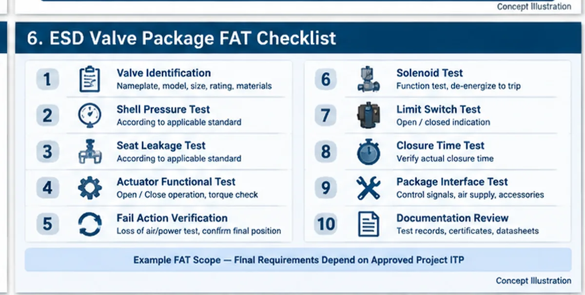
| Test / Inspection Item | Verification Objective |
|---|---|
| Identificazione valvola | Confirm model, size, rating and configuration |
| Material documentation | Review specified material records |
| Shell test | Verify pressure-boundary integrity |
| Seat test | Verify specified shut-off acceptance |
| Actuator functional test | Confirm movement and operation |
| Fail-action test | Verify specified response to the defined failure condition |
| Solenoid test | Verify command and response |
| Limit-switch test | Confirm open/closed feedback |
| Closure-time test | Record actual response time |
| Package interface test | Verify agreed electrical and pneumatic interfaces |
| Revisione documentazione | Check test reports and approved records |
The exact FAT scope should be agreed before manufacturing or testing begins. Not every project requires every test listed above. The approved datasheet, inspection and test plan, purchase specification and safety requirements determine the final acceptance scope.
8. ESD Valve vs On-Off Valve: RFQ and Package Specification Checklist
When requesting quotations, buyers should avoid describing the application only as an actuated on-off valve. If the intended duty is emergency shutdown, this must be stated explicitly. The following information helps suppliers evaluate the correct package configuration.
| RFQ Field | Information to Provide |
|---|---|
| Funzione della valvola | Normal on-off / Emergency shutdown |
| Tipo di valvola | Ball / Butterfly / Gate / Other |
| Dimensione nominale | DN / NPS |
| Classe di pressione | Class / PN and design conditions |
| Connessione di estremità | Flanged / Butt weld / Other |
| Materiale del corpo | Project-specified material |
| Materiale sede | Based on medium and operating conditions |
| Operating medium | Fluid composition and phase |
| Pressione e temperatura | Normal and design values |
| Actuator type | Pneumatic / Electric / Hydraulic |
| Valve torque / thrust basis | Supplier data source, revision and values across the required stroke |
| Maximum shut-off differential pressure | Defined process case and flow direction(s) |
| Minimum operating utility | Minimum available air / hydraulic pressure or electrical supply condition |
| Actuator sizing evidence | Calculation / selection sheet, output throughout stroke and applicable project margin |
| Azione di fail | FC / FO / FIP, tied to each specified failure scenario |
| Operating supply | Air / Hydraulic / Electrical requirements |
| Closure time | Required time and measurement definition |
| Control interface | DCS / SIS / Other |
| Accessori | SOV / Limit Switch / Position Feedback |
| Collaudi | Pressure / Functional / FAT / Proof-test requirements |
| Documentazione | Datasheet / ITP / Test Reports / Material Records |
Additional project documents may include the approved valve datasheet, Piping and Instrumentation Diagram (P&ID), cause-and-effect chart, Safety Requirements Specification (SRS) where applicable, instrument and electrical interface drawings, approved actuator and accessory datasheets, Inspection and Test Plan (ITP), and documentation and traceability requirements.
The more clearly these requirements are defined, the easier it becomes to compare technical quotations on an equivalent basis.
9. Common ESD Valve Specification and Testing Mistakes
| Errore comune | Potential Consequence | Recommended Review |
|---|---|---|
| Treating every actuated on-off valve as an ESD valve | Safety requirements may be overlooked | Identify the assigned safety function |
| Assuming every ESD valve must fail close | Incorrect safe-state selection | Review the hazard analysis and SRS |
| Specifying closure time without process analysis | Pressure surge or inadequate response | Confirm process and transient requirements |
| Testing only the valve body | Actuator and accessory problems may remain undetected | Define package-level testing |
| Treating PST as a complete proof test | Some dangerous failure modes may remain undetected | Review proof-test coverage |
| Omitting solenoid and feedback checks | Interface problems may appear during commissioning | Include agreed accessory verification |
| Failing to define test conditions | Test results may not represent actual duty | Specify supply, pressure and measurement boundaries |
| Comparing quotations with different testing scopes | Commercial and technical bids become inconsistent | Normalize the ITP and documentation requirements |
A technically acceptable quotation should clearly identify what is included, what is excluded and which requirements remain subject to project confirmation.
Practical Failure-Mode Review for an ESD Package
| Potential Failure | Possible Effect | Review or Test Evidence |
|---|---|---|
| Valve or stem sticking | Slow movement or failure to reach the required position | Full-stroke test, travel-time trend and inspection records as defined by the procedure |
| Insufficient actuator output | Failure to move the valve under required differential pressure | Actuator sizing basis and test at agreed supply/process conditions |
| Solenoid malfunction | Trip signal does not produce the intended pneumatic or hydraulic response | Solenoid functional test and specified signal-failure simulation |
| Air leakage or restricted tubing | Reduced actuator force or delayed stroke | Leak inspection, supply-pressure check and response-time record |
| Limit-switch misadjustment | Incorrect open/closed indication | Mechanical position check and contact-state verification |
| Incorrect wiring or interface logic | Unexpected command, missing trip or incorrect feedback | Approved drawing review and end-to-end interface test where included |
| Incomplete proof-test coverage | Some dangerous undetected failure modes remain untested | Proof-test procedure mapped to failure modes and SIF verification assumptions |
This is a screening list for specification and supplier review. It is not a substitute for the project FMEA, failure-rate data, safety manual or approved proof-test procedure.
10. How to Compare ESD Valve Package Quotations
When several suppliers quote the same nominal valve size and pressure class, the packages may still differ in actuator basis, accessories, test boundaries and documentation. Procurement should normalize the technical scope before comparing price or delivery.
| Bid Comparison Item | Fornitore A | Fornitore B | Buyer Check |
|---|---|---|---|
| Valve construction and materials | As quoted | As quoted | Match approved datasheet and material specification |
| Actuator sizing basis | As quoted | As quoted | Check required torque/thrust across the full stroke and specified conditions |
| Fail action and failure cases | As quoted | As quoted | Compare each specified loss-of-energy and signal scenario |
| Closure-time definition | As quoted | As quoted | Confirm identical start/end events and test conditions |
| Solenoid and accessories | As quoted | As quoted | Compare voltage, enclosure, connection, operating state and required feedback |
| FAT scope | As quoted | As quoted | Compare test list, witness points, records and exclusions |
| Functional-safety documents | As quoted | As quoted | Check applicability, device configuration and evidence boundaries |
| Documentation and traceability | As quoted | As quoted | Compare certificates, material records, test reports and final dossier |
Use this as a bid-normalization worksheet. Replace “as quoted” with each supplier’s exact offered value, deviation or exclusion. Do not award technical equivalence based only on the valve body description.
Procurement example: two quotations may list the same valve size and pressure class, yet one may include actuator sizing at minimum air pressure and the other may assume nominal air pressure. The apparent price difference is not a like-for-like comparison until the utility basis, maximum differential pressure, fail action, response-time boundary and FAT inclusions are normalized.
11. Frequently Asked Questions
Is an ESD valve the same as an on-off valve?
No. An on-off valve describes a valve’s operating function, while an ESD valve is assigned an emergency shutdown function. An ESD valve may use an on-off valve design, but ordinary on-off operation alone does not establish ESD suitability.
Can a standard on-off valve be used as an ESD valve?
Potentially, yes. However, the complete assembly must meet the project’s safety requirements, including the required fail action, actuator performance, control interface, functional-safety evidence and testing scope.
Are all ESD valves fail-close?
No. The required fail position depends on the process hazard analysis and defined safe state. Fail close, fail open or another specified response may be appropriate depending on the application.
What determines the required ESD valve closure time?
Closure time depends on the safety response requirement, valve characteristics, actuator performance, available operating energy, accessories and process dynamics. Hydraulic transient analysis may also be necessary where rapid closure could create pressure surges.
What is the difference between an ESD valve and a shutdown valve?
The terms are sometimes used interchangeably in industry, but their exact meaning depends on the project terminology and functional requirements. The buyer should confirm whether the valve is assigned to a formal safety instrumented function or another shutdown arrangement.
Does an ESD valve need SIL certification?
There is no single answer that applies to every valve application. The complete safety function must meet its specified functional-safety requirements. Relevant product and subsystem documentation should be reviewed as part of the overall assessment.
What tests are required for an ESD valve package?
The agreed test scope may include shell and seat pressure tests, actuator functional testing, fail-action verification, solenoid operation, position feedback, closure-time measurement and package FAT. The final scope depends on the project specification and approved ITP.
Does partial-stroke testing replace a full-stroke proof test?
No. Partial-stroke testing detects only selected failure modes and does not demonstrate full travel to the required safe position or complete shut-off performance. Its diagnostic credit and relationship to full proof testing must be justified in the SIF verification and proof-test strategy.
Does a successful package FAT prove the complete SIF?
Not automatically. FAT verifies only the scope and interfaces included in the approved test procedure. Site installation, field devices, wiring, logic solver configuration and end-to-end safety-function validation may require separate verification.
12. Conclusion: Select the Function Before the Valve Package
The key difference between an ESD valve and a standard on-off valve is the responsibility assigned to the valve within the process system. An ordinary on-off valve provides operational isolation. An ESD valve must perform a defined emergency shutdown action as part of the applicable safety arrangement. This article addresses the comparison decision, while the separate ESD engineering solution page covers the wider project review and requirement-to-evidence framework.
For project procurement, the review should go beyond valve type and pressure rating. Fail action, closure time, actuator configuration, solenoid interfaces, position feedback, testing and documentation all need to be defined.
A complete package specification helps engineering teams assess technical suitability and allows procurement teams to compare supplier quotations on a consistent basis.
Request an ESD Valve Package Review
Send your valve datasheet, process medium, operating and design pressure, temperature, valve size, pressure rating, required fail action, closure time, actuator type, control interface and testing requirements.
Raymon Valve can review the submitted technical requirements and identify the information needed for a project-specific valve and actuation quotation.
Contatta Raymon ValveEngineering References and Further Reading
- IEC 61511-1 – Functional safety: Safety instrumented systems for the process industry sector. Consult the edition and amendments adopted by the project.
- UK HSE – Functional safety. Overview of SIS elements and their role in achieving a safe process state.
- ISA-TR96.05.02-2022 – In-Situ Proof Testing of Automated Valves. Refer to the publisher page for the publication scope and availability.
 Italian
 English
 German
 Arabic
 French
 Spanish
 Portuguese
 Russian