
Control Valve Engineering · Sizing Review
By Raymon Valve · Technical content
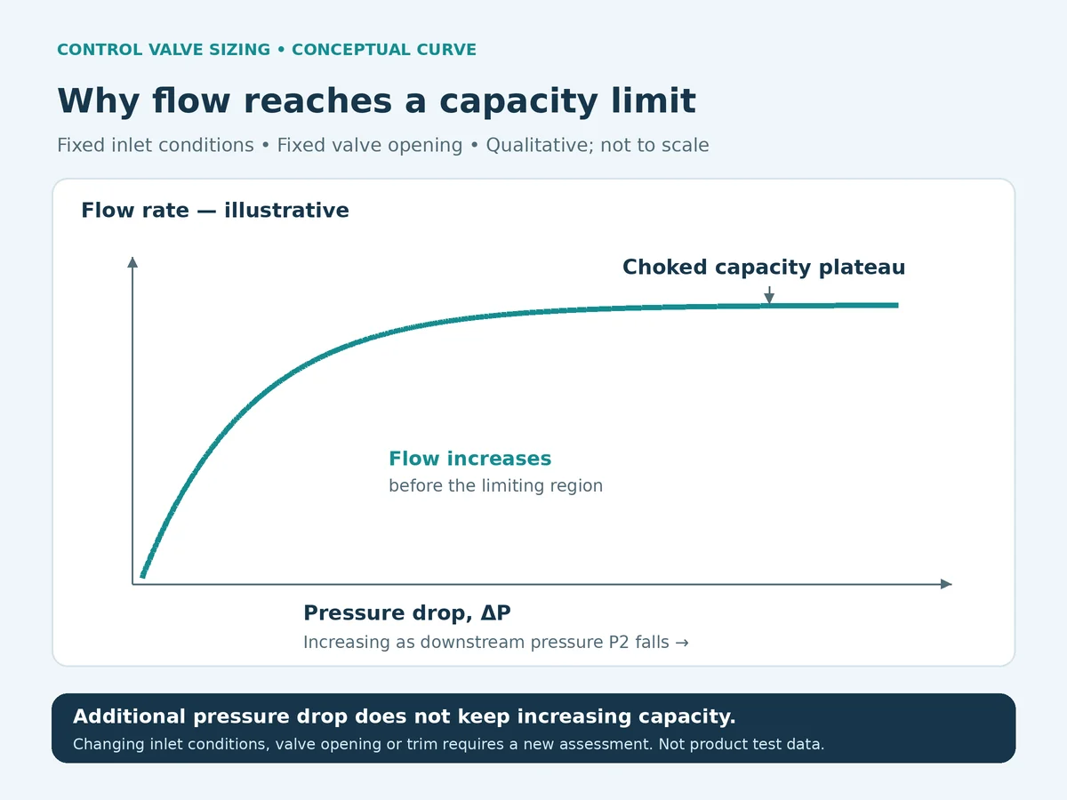
Choked flow in control valves means that lowering downstream pressure no longer increases capacity when upstream conditions and effective flow area remain fixed. Gas and liquid services reach this limit through different mechanisms, so a single critical pressure ratio cannot size every valve. A choked valve may still pass the required flow, and changing its opening can change capacity. Review the correct pressure ratio, valve-specific factors and operating travel for each duty, then assess noise, outlet velocity and suitability separately before accepting a supplier’s sizing sheet. [1]On this page
- What Does Choked Flow Mean in a Control Valve?
- How Is the Critical Pressure Ratio Determined for Gas?
- How Does Liquid Choked Flow Differ?
- What Does Choked Flow Change About Required Cv?
- How Should Noise and Velocity Be Reviewed?
- Worked Screening Examples
- Compare Supplier Sizing Sheets
- Control Valve Sizing Review Checklist
- When Should Trim or System Changes Be Evaluated?
- Ask for Control Valve Sizing Support
- Domande frequenti
- Nota tecnica
- Official References
What Does Choked Flow Mean in a Control Valve?
“Choked” describes a hydraulic or compressible-flow limitation. It does not mean the flow passage is physically blocked.
For gas capacity comparisons, use mass flow or volumetric flow referred to the same stated standard conditions. Actual outlet volumetric flow depends on the outlet state and is not interchangeable with either quantity when downstream pressure changes.
The fixed-condition qualification matters. Changing valve travel, upstream pressure or fluid state changes the calculation. An operating trend in which flow stops rising can also reflect other system constraints; a flat flow trend alone does not identify choking.
Quick Review: Capacity, Noise and Damage
Use three separate questions before accepting a sizing sheet:
Swipe or scroll horizontally to read the full table.
| Review | Question to resolve | Evidenza da richiedere |
|---|---|---|
| Capacità | Can the proposed construction pass the specified flow at the corresponding pressures? | Calculation method, applicable coefficients and predicted travel for each case |
| Noise and velocity | Do the predicted results meet the stated project requirements? | Prediction basis, evaluation location, fluid state and piping assumptions |
| Mechanical suitability and control | Is the construction appropriate across the operating envelope? | Trim/material review, usable travel, shutoff and actuation assessment |
Passing the capacity review does not close the other two. A procurement comparison should retain these as separate acceptance items.
Decide What the Calculation Allows You to Conclude
- Hold the selection: paired operating cases, fluid properties, applicable coefficients or method assumptions are missing. Ask for the missing record before accepting a final size.
- Request further engineering review: the capacity result is available, but noise, outlet conditions, phase behavior or operating travel remain unresolved. State the open item explicitly.
- Submit for project acceptance: each applicable review has a documented result and technical deviations have been addressed. The responsible project authority determines acceptance; the choking flag alone is neither approval nor rejection.
How Is the Critical Pressure Ratio Determined for Gas?
Define Which Pressure Ratio You Mean
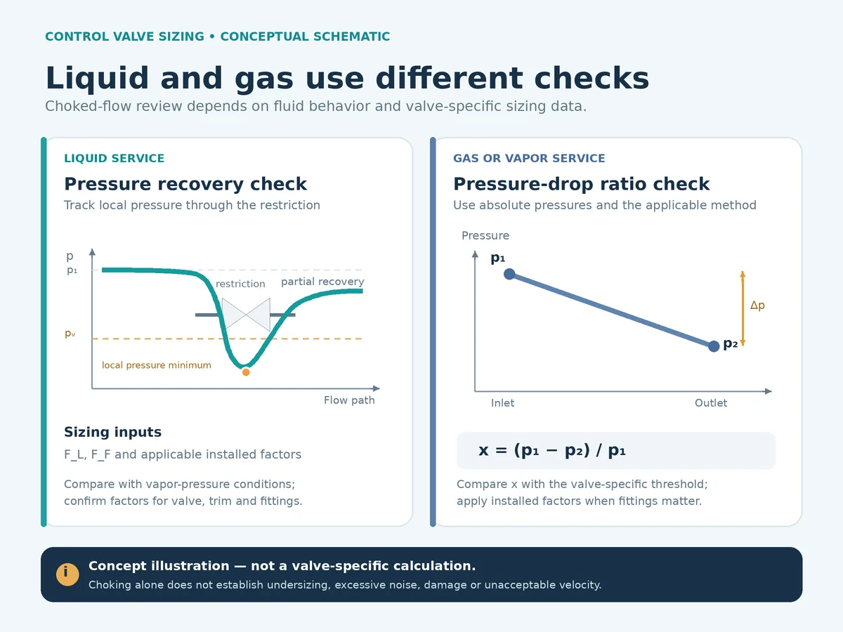
For the conventional gas-sizing framework discussed here:
x = (P1 − P2) / P1
Here, P1 and P2 are upstream and downstream absolute static pressures at the locations required by the method. The outlet-to-inlet ratio is P2/P1 = 1 − x. A quoted “critical pressure ratio” is ambiguous unless the ratio is defined.
For applicable conditions without attached fittings, the choking threshold is expressed as:
x_choked = Fγ × xT, where Fγ = k / 1.40
Here, k is the specific-heat ratio and xT is the valve pressure-drop ratio factor. Some references label the specific-heat factor Fk. Compare actual x with this threshold; use the limiting ratio in the applicable capacity equation once choking is reached. Attached fittings require the appropriate installed treatment, including xTP where applicable. [2]
Why Valve Data Matters More Than a Universal Ratio
Do not substitute a universal nozzle pressure ratio for manufacturer valve data. Specify the proposed body, trim and operating travel, and request the associated factors. A full-open factor is not automatically appropriate at the predicted operating position.
The review should also identify gas composition, temperature, molecular weight or density, compressibility and flow reference conditions. “Nm³/h” or “SCFM” needs an explicit reference temperature and pressure. Do not compare standard volumetric flow directly with actual outlet volumetric flow.
Illustrative data-review scenario: a gas duty is copied into an RFQ as “m³/h” without reference conditions. One supplier treats it as standard flow while another treats it as actual inlet flow, so the capacity results are not comparable. Confirm the flow basis and the pressure/temperature used for conversion, then issue the same corrected input to both suppliers.
For wet, condensing, multiphase or otherwise unusual service, ask the supplier to state whether the selected method applies before relying on the result.
How Does Liquid Choked Flow Differ?
The following limiting-pressure-drop relationship is used within the applicable conventional liquid-sizing method, shown here for turbulent Newtonian-liquid service without attached fittings. Non-turbulent service requires the appropriate corrections and an applicability check. It is not a general sizing model for an existing two-phase inlet, non-Newtonian fluid or solids-bearing stream. For multicomponent liquids, confirm the method and fluid-property basis rather than assigning a single vapor pressure and critical pressure by assumption. [3]
ΔP_choked = FL² × (P1 − FF × Pv)
FF = 0.96 − 0.28 × √(Pv/Pc)
FL is the liquid pressure-recovery factor; FF is the liquid critical pressure-ratio factor; Pv is vapor pressure at inlet temperature; Pc is thermodynamic critical pressure. Use absolute pressures consistently. The capacity calculation limits its sizing pressure drop to the choking value when actual pressure drop exceeds it. FL must match the selected construction. [1]
With attached fittings, use the applicable FP/FLP treatment rather than silently retaining the bare-valve calculation. The installed limiting pressure-drop expression uses (FLP/FP)² in place of FL². [2]
- FP — piping geometry factor: accounts for the attached-fitting influence in the applicable installed sizing calculation.
- FLP — combined liquid pressure-recovery and piping geometry factor: applies to the valve with attached fittings in the liquid method.
- xTP — installed pressure-drop ratio factor: applies to the valve with attached fittings in the gas method.
These installed factors have different roles from FF, the liquid critical pressure-ratio factor; they are not interchangeable damage-severity indices. Obtain the factors for the proposed configuration. IEC 60534-2-3 describes flow-capacity tests for these coefficients, but citing that standard does not establish that a particular product has been tested. [6]
Choking, Cavitation and Flashing Require Different Conclusions
The onset of vapor formation or incipient cavitation does not, by itself, demonstrate that the valve has reached its choked capacity limit. Use the applicable choking criterion and valve data to assess the capacity limit; evaluate cavitation severity separately.
Cavitation involves vapor formation followed by collapse as pressure recovers; flashing involves vapor that persists downstream. A capacity limit is not a prediction of damage rate. The review needs fluid properties, pressure recovery and construction-specific evidence before drawing conclusions about erosion or service life. [1]
For damage mechanisms and mitigation, see the control valve cavitation vs flashing guide. The distinction helps identify which additional assessment is required.
What Does Choked Flow Change About Required Cv?
Required Cv, Rated Cv and Cv at Operating Travel
Required Cv is the capacity needed for a defined operating case under a specified calculation method. Rated Cv describes the manufacturer’s stated capacity at its rated condition. Cv at operating travel describes the capacity at a particular opening.
A quotation should connect these values. Nominal size does not establish effective flow area, and a large rated Cv does not show where the valve will operate during minimum or normal flow.
Illustrative bid-review scenario: two offers list the same rated Cv, but one predicts an acceptable normal-flow opening and the other predicts operation close to its travel limit. The offers may use different trim curves, pressure assumptions or coefficients at the assessed opening. Request both calculation sheets on the same operating-case basis and reconcile the selected trim data before treating the offers as equivalent.
Can Increasing Cv Increase Flow After Choking?
Yes, changing effective flow area can change capacity. Choking limits the response to further downstream pressure reduction under the fixed conditions used to define it. It does not freeze capacity for every valve opening or trim configuration. Recalculate after changing the valve or opening. [1]
Request a consistent solution: predicted travel, available Cv and applicable coefficients should describe the same configuration. Where the first calculation uses assumed factors, the supplier should explain how the final selection was checked.
Check the Pressure Basis Before Comparing Results
For each case, identify where P1 and P2 are evaluated and how the valve pressure drop was obtained from the system. Request the pipe internal diameters and attached-fitting arrangement used in the calculation. Two suppliers using different pressure locations or piping assumptions have not assessed the same case, even if their quoted nominal size matches.
Keep operating cases separate from pressure-boundary design requirements. Include the design pressure, design temperature, pressure class and end connections for mechanical selection, but use the confirmed case-specific flow, pressures and temperature for sizing. A pressure-class label is not a fixed allowable pressure: confirm the applicable pressure-temperature rating and the separate limits of body, trim, seat, packing and gaskets. Ask the supplier to flag assumed values rather than silently completing a blank datasheet field.
A steady-state Cv calculation does not establish transient system behavior. If a rapid pressure change, stroking sequence or startup event is part of the duty, identify the separate assessment and actuator response requirements instead of assuming that the normal-flow sizing case covers the event.
Why a Larger Valve Is Not an Automatic Solution
Before increasing capacity, ask what failed: maximum-flow capacity, normal-flow control, acoustic performance, erosion assessment or downstream piping requirements. These are different design problems.
A revised selection should show minimum, normal and maximum cases together. Preserve any startup, bypass, depressurization or upset cases that actually apply to the project. Do not combine an unrelated maximum flow and maximum pressure drop into an undocumented sizing case.
For the broader input requirements, see the Guida al dimensionamento delle valvole di regolazione.
How Should Noise and Velocity Be Reviewed?
Specify the Noise Prediction Basis
Ask the supplier to identify the prediction method, operating case, result units, evaluation location and piping assumptions. A statement such as “low-noise trim” does not establish compliance with a project limit.
IEC 60534-8-3:2010 addresses aerodynamic noise prediction within its stated scope, including single-phase dry gases and vapours. IEC 60534-8-4:2015 addresses noise generated by liquid flow. These are separate methods; the appropriate one depends on the service. [4] [5]
State the required sound-pressure limit and assessment location in the purchase specification. If the prediction exceeds the requirement, record the proposed corrective measure and the calculation supporting it. An external sound-pressure result also does not, by itself, close every vibration or mechanical assessment.
Illustrative acceptance-review scenario: a proposal passes the flow-capacity check and reports an acceptable noise level, but its prediction assumes a different downstream pipe from the installation drawing. Request the pipe geometry, wall thickness and evaluation location used for that prediction. Reconcile those inputs and obtain the revised result before accepting the acoustic claim.
Separate Local Flow Conditions from Outlet Velocity
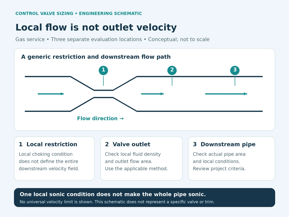
Distinguish the trim passage, valve outlet and downstream pipe. A local sonic condition is not a complete description of the downstream line. [1]
For a single-phase outlet check, identify actual outlet density and internal area. Continuity gives mean velocity as v = mass flow / (density × area). A Mach-number check additionally needs the local speed of sound. Both require compatible units and the correct local thermodynamic state.
For flashing or other two-phase flow, a single-phase density substitution is not an adequate assessment. Request the selected model and its limitations.
Any velocity limit should identify its source and evaluation location. Record the purchaser’s requirement or the manufacturer’s documented criterion instead of presenting an unexplained universal number.
Worked Screening Examples
These original examples illustrate threshold checks only. The coefficients and fluid properties are assumed teaching inputs, not Raymon Valve product data. Neither example selects a valve size, predicts noise or approves service.
Gas Case: Check the Choking Threshold
Assume an applicable single-phase gas calculation, no attached fittings, P1 = 10 bar absolute, P2 = 4 bar absolute, k = 1.40 and xT = 0.50 at the assessed opening.
Swipe or scroll horizontally to read the full table.
| Step | Calculation | Result |
|---|---|---|
| Actual pressure-drop ratio | (10 − 4) / 10 | x = 0.60 |
| Specific-heat factor | 1.40 / 1.40 | Fγ = 1.00 |
| Threshold | 1.00 × 0.50 | x_choked = 0.50 |
| Confronto | 0.60 > 0.50 | Choked under these assumptions |
Reducing P2 to 3 bar absolute raises actual x to 0.70. It does not increase the limiting ratio used in this capacity calculation with the other assumptions fixed.
This establishes a threshold result only. Required flow, temperature, gas properties and the appropriate capacity equation are still needed to determine Cv. A different opening or trim requires its own assessment.
Liquid Case: Check the Limiting Sizing Pressure Drop
Assume an applicable turbulent Newtonian-liquid calculation, no attached fittings, P1 = 10 bar absolute, P2 = 2 bar absolute, Pv = 1 bar absolute, Pc = 100 bar absolute and FL = 0.80 at the assessed opening.
Swipe or scroll horizontally to read the full table.
| Step | Calculation | Result |
|---|---|---|
| Fluid factor | 0.96 − 0.28 × √(1/100) | FF = 0.932 |
| Limiting pressure drop | 0.80² × (10 − 0.932 × 1) | ΔP_choked ≈ 5.80 bar |
| Actual pressure drop | 10 − 2 | ΔP = 8.00 bar |
| Sizing comparison | Use the lesser pressure drop | Approximately 5.80 bar |
Because actual pressure drop exceeds the limit, an unrestricted liquid-capacity calculation using the full 8 bar would be inappropriate. Flow and density are still needed to calculate required Cv. P2 above Pv does not rule out local cavitation; this example does not quantify its severity.
How Should You Compare Two Supplier Sizing Sheets?
Normalize the calculation basis before comparing price, nominal size or rated Cv. Use this bid-review schedule to expose differences that the headline capacity result can hide.
Swipe or scroll horizontally to read the full table.
| Difference found | Request from both suppliers | Review disposition |
|---|---|---|
| Different flow or pressure basis | The same numbered case matrix, pressure locations and flow reference conditions | Recalculate on an agreed basis before ranking capacity |
| Same rated Cv, different predicted travel | The selected trim curve and the coefficients used at each stated opening | Resolve configuration or assumption differences; do not compare rated Cv alone |
| One bid omits reducers or attached fittings | The installation sketch and applicable installed factors | Reconcile the installed calculation and its limits |
| Both claim compliance with a noise limit | The same assessment location, weighting convention and stated pipe assumptions | Compare the prediction basis as well as the reported level |
| One quote supplies only a body and trim | Actuator, positioner, fail action, utility basis, leakage requirement and exclusions | Normalize package scope; a capacity result does not settle actuator selection |
Retain the accepted calculation revision, coefficient source, configuration and deviation list with the tag datasheet. If the trim, pipe arrangement or process basis changes, identify which calculations and reviews must be repeated. This makes the quotation traceable to the eventual supplied package.
Control Valve Sizing Review Checklist
Complete a separate record for each paired set of flow, pressure and temperature conditions.
Swipe or scroll horizontally to read the full table.
| Elemento di revisione | Record richiesto | Hold point |
|---|---|---|
| Case identity | Tag, operating mode, flow, P1, P2 and temperature | Resolve inconsistent case inputs |
| Fluid basis | Composition, phase, property source and flow reference conditions | Resolve missing properties or uncertain phase |
| Metodo di calcolo | Standard/version, software and applicability statement | Obtain a justified method for exceptional service |
| Configurazione della valvola | Model, size, trim and proposed travel | Identify the exact configuration being assessed |
| Coefficients | Cv curve and applicable FL, xT or installed factors | Replace undocumented generic assumptions |
| Capacità | Required Cv, available capacity and choking result | Recalculate if configuration or conditions change |
| Noise | Method, location, piping assumptions and project limit | Resolve unassessed cases or exceedances |
| Outlet and piping | Evaluation area, fluid state, velocity and applicable criterion | Obtain additional assessment where necessary |
| Control and shutoff | Operating range, leakage requirement, fail action and actuator basis | Resolve package-level gaps before approval |
| Deviazioni | Accepted exceptions, open items and responsible reviewer | Retain unresolved items as explicit holds |
Use IEC 60534-2-1:2011, including its 2015 corrigendum, as a reference for applicable sizing equations—not as proof that every service lies within the method. Its published scope identifies limitations for non-Newtonian fluids, slurries and other complex services. A standard citation does not certify a particular valve. [3]
When Should Trim or System Changes Be Evaluated?
Frame the change around the unresolved requirement and ask for evidence that the revision addresses it.
Swipe or scroll horizontally to read the full table.
| Unresolved requirement | Direction to evaluate | Evidence before acceptance |
|---|---|---|
| Maximum-flow capacity | Alternative capacity, trim or body configuration | Revised calculations and travel across all cases |
| Gas noise | Noise-attenuating construction or system pressure-drop allocation | Acoustic prediction, capacity and outlet review |
| Cavitation assessment | Pressure-staging or anti-cavitation approach | Service-specific assessment and limitations |
| Flashing/two-phase outlet | Outlet geometry, materials and downstream arrangement | Appropriate phase/velocity and erosion review |
| Limited usable control range | Capacity and installed characteristic review | Predicted operating behavior across the range |
These are review directions, not universal prescriptions. Pipe and system changes require the responsible engineering authority’s assessment. Refer to the Valvole di regolazione category for product context, then evaluate the exact proposed construction against the datasheet.
Ask for Control Valve Sizing Support
For an initial review, send the following information together so the proposed capacity and configuration can be checked against the same duty:
- Duty and fluid: tag number, control objective, composition and phase; identify solids or uncertain fluid-property data.
- Paired operating cases: minimum, normal and maximum flow with the corresponding inlet pressure, outlet pressure and temperature; identify absolute or gauge units and flow reference conditions. Add startup or upset cases where applicable.
- Installation and mechanical requirements: pipe internal diameters, reducers or other attached fittings, design pressure/temperature, connection requirements and available installation space.
- Acceptance and package scope: noise and velocity criteria with their evaluation locations, shutoff requirement, operating range, fail action and available utilities.
If any input is unavailable, mark it as unknown and identify its owner. Request clarification of the calculation basis before treating a preliminary proposal as an approved selection.
For an existing proposal, attach the sizing sheet, trim designation, Cv-versus-travel data, coefficient basis and technical deviations. For an operating problem, include available trends and inspection findings without changing plant conditions solely to reproduce a suspected choke point.
Ask for Control Valve Sizing Support
For company background, see Chi siamo.
Final valve selection depends on confirmed process data, applicable calculation methods, manufacturer data, material compatibility, shutoff and actuation requirements, installation conditions and project approval.
Domande frequenti
What causes choked flow in a control valve?
In conventional gas service, choking is associated with a local sonic condition at the restriction. In liquid service, vapor formation can lead to a capacity limit, but the onset of vapor formation alone does not prove choking. Assess the limit at fixed upstream conditions and effective flow area using the appropriate method and valve-specific factors. Physical blockage is a separate issue.
Is the critical pressure ratio the same for every control valve?
No. Define the ratio being quoted and identify the applicable valve, trim, opening, fluid properties and installed corrections.
Can increasing Cv increase flow in choked service?
It can, because changing effective flow area changes the fixed-condition comparison. Recalculate capacity and operating behavior for the revised configuration.
Can liquids experience choked flow?
Yes. Liquid sizing can reach a limiting pressure drop associated with vapor formation. Evaluate cavitation or flashing separately from the capacity calculation.
Does choked flow always cause excessive noise or damage?
No. Request the relevant noise and mechanical assessments rather than using the choking flag as an acceptance or rejection criterion.
Does sonic flow inside the valve mean the outlet pipe is sonic?
No. Establish outlet conditions, actual flow, pipe internal area and local speed of sound before drawing that conclusion.
What is needed to review a choked-flow sizing calculation?
A paired operating-case matrix, fluid properties, valve/trim identification, applicable coefficients, installation data and documented capacity, noise, velocity and control requirements.
Engineering Note: Scope and Selection Limits
This article supports preliminary datasheet and supplier-calculation review. Its assumed examples do not establish a Raymon Valve product rating, final Cv, nominal size, noise level, trim life or actuator size. No tag-specific product calculation or signed engineering review is presented here.
Final selection requires confirmed process and installation data, an applicable sizing method, exact manufacturer coefficients and the required material, pressure-temperature, shutoff, actuation and project checks. For service outside a method’s stated scope, obtain a justified assessment rather than extending the simplified equations by assumption.
Official References
- Emerson/Fisher, Understanding Choked Flow in Fisher Valves, D104173X012, September 2017. General definitions, liquid threshold equation and misconceptions; not Raymon Valve product evidence. Bibliographic reference.
- Emerson/Fisher, Catalog 12, Section 2: ANSI/ISA/IEC Valve Sizing, February 2018 pages as displayed. Gas ratio relationships, installed factors and sizing terminology. This explanatory publication does not replace the controlling project standard. Bibliographic reference.
- IEC 60534-2-1:2011, Industrial-process control valves — Part 2-1: Flow capacity — Sizing equations for fluid flow under installed conditions. Edition 2.0; official listing includes the April 2015 corrigendum. IEC 60534-2-1 sizing equations
- IEC 60534-8-3:2010, Industrial-process control valves — Part 8-3: Noise considerations — Control valve aerodynamic noise prediction method. Edition 3.0. Bibliographic reference.
- IEC 60534-8-4:2015, Industrial-process control valves — Part 8-4: Noise considerations — Prediction of noise generated by hydrodynamic flow. Edition 3.0. Bibliographic reference.
- IEC 60534-2-3:2015, Industrial-process control valves — Part 2-3: Flow capacity — Test procedures. Edition 3.0; the public scope identifies tests for flow-capacity coefficients, including FP, FLP, xT and xTP. It is not evidence of a specific product test. Bibliographic reference.
 Italian
 English
 German
 Arabic
 French
 Spanish
 Portuguese
 Russian