
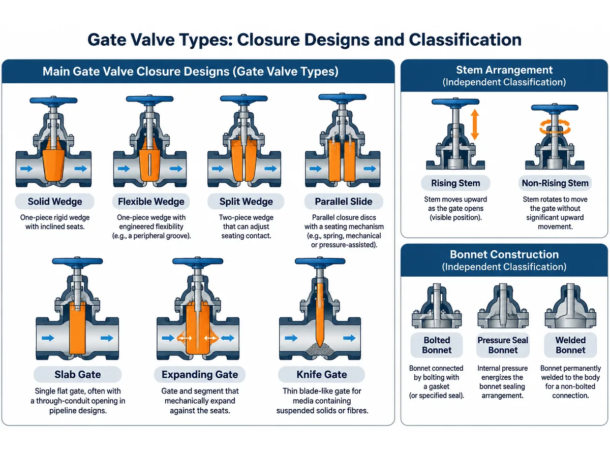
The main gate valve types are solid wedge, flexible wedge, split wedge, parallel slide, slab, expanding gate and knife gate designs. They differ in gate geometry, seating mechanism and intended service—not simply in name. For industrial isolation, the right type depends on the process medium, pressure and temperature, differential pressure, solids, shut-off duty, installation envelope and required inspection evidence. This guide explains the construction differences and gives engineers and procurement teams a practical basis for screening designs and preparing a comparable gate valve RFQ.
What Are the Main Types of Gate Valves?
A gate valve is a linear-motion isolation valve in which a gate moves approximately perpendicular to the flow direction. When fully open, the gate is generally withdrawn from the main flow passage, providing a relatively unobstructed flow path. When closed, the gate contacts the seating surfaces to stop flow.
Gate valves are primarily designed for fully open or fully closed service. They are generally unsuitable for continuous throttling because partially open operation can produce high local velocities, vibration and accelerated wear of the gate and seats.
Gate valves can be classified using several independent design dimensions:
- Gate or disc construction: solid wedge, flexible wedge, split wedge, parallel disc, slab or expanding gate.
- Application-specific construction: knife gate and through-conduit pipeline designs.
- Stem arrangement: rising stem or non-rising stem.
- Bonnet construction: bolted bonnet, pressure seal bonnet or welded bonnet.
- Operation method: manual handwheel, gearbox, electric actuator or pneumatic actuator.
These categories should not be treated as mutually exclusive. A gate valve may combine a particular gate design with a rising stem, pressure seal bonnet and electric actuator.
Wedge Gate Valve Types
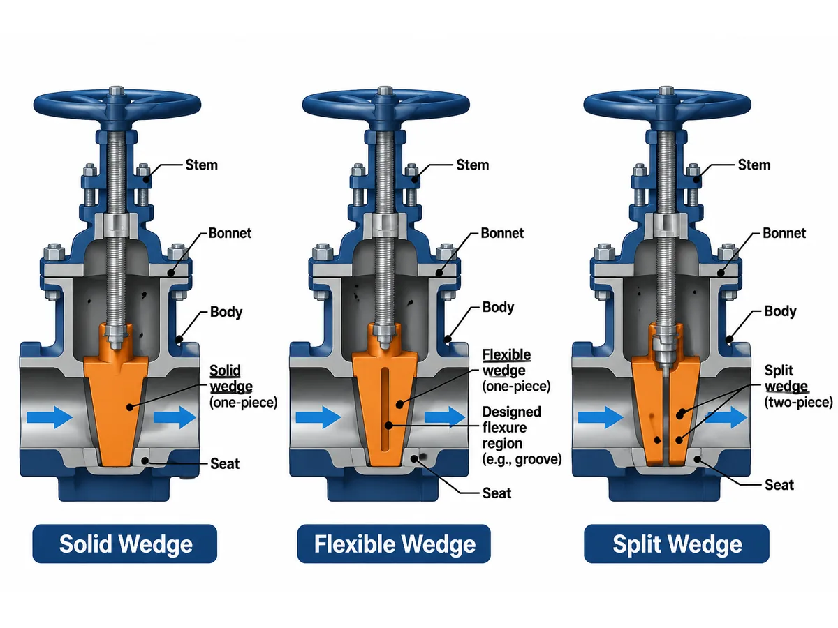
Wedge gate valves use an inclined closure element that moves between matching inclined seats. The wedge geometry generates seating contact as the gate reaches its closed position.
Solid Wedge Gate Valve
A solid wedge gate valve uses a single rigid wedge-shaped closure element. Its relatively simple construction makes it a common choice for general industrial isolation applications.
- One-piece rigid wedge construction.
- Inclined seating surfaces.
- Mechanical seating through wedge movement.
- Relatively straightforward closure-element design.
- Potential sensitivity to thermal distortion and seat misalignment.
Applicazioni tipiche: general water pipelines, oil and gas isolation, utility systems and selected steam and process applications.
Engineering consideration: Thermal expansion and contraction can affect the relationship between the body seats and the rigid wedge. Under certain operating conditions, distortion or differential thermal movement may increase the risk of binding. Suitability depends on the valve design, temperature cycle, materials and installation conditions.
Field review example: If a valve becomes difficult to operate after a hot start-up or repeated temperature cycles, record the temperature history, pressure differential and travel/torque trend before attributing the problem to the wedge. Internal inspection and the manufacturer’s design limits are needed to distinguish thermal distortion from deposits, stem damage or actuator issues.
Flexible Wedge Gate Valve
A flexible wedge gate valve uses a one-piece wedge with engineered flexibility, commonly achieved through a peripheral groove or another designed flexure arrangement. This flexibility allows the wedge to accommodate limited differences in seat alignment and body deformation.
- One-piece flexible wedge.
- Controlled elastic deformation.
- Accommodation of certain thermal and seating movements.
- Reduced sensitivity to some forms of seat-angle mismatch compared with a rigid wedge.
Applicazioni tipiche: steam systems, power generation and process pipelines with temperature cycling, where the specified design is suitable.
Engineering consideration: Wedge flexibility is a design feature, not permission to ignore temperature limits or mechanical stresses. Review the actual wedge geometry, material, thermal operating cycle and seating arrangement.
Fabrication review example: A flexible-wedge description on a quotation is not enough to establish the supplied construction. Compare the sectional drawing, gate material and specified flexure geometry with the approved datasheet; record any deviation before manufacturing release.
Split Wedge Gate Valve
A split wedge gate valve uses two separate wedge segments that can adjust their seating contact independently. This arrangement can accommodate certain differences between the two seating surfaces.
- Two-piece closure construction.
- Independently adjustable seating contact.
- Accommodation of some seat-alignment variations.
- More internal components than a simple solid wedge design.
Applicazioni tipiche: selected gas and liquid isolation duties and applications where the specified design benefits from a split closure element.
Engineering consideration: Review the segment mechanism, internal clearances and seating arrangement against the medium and operating conditions. Split wedge and double-disc valves should not automatically be treated as identical designs.
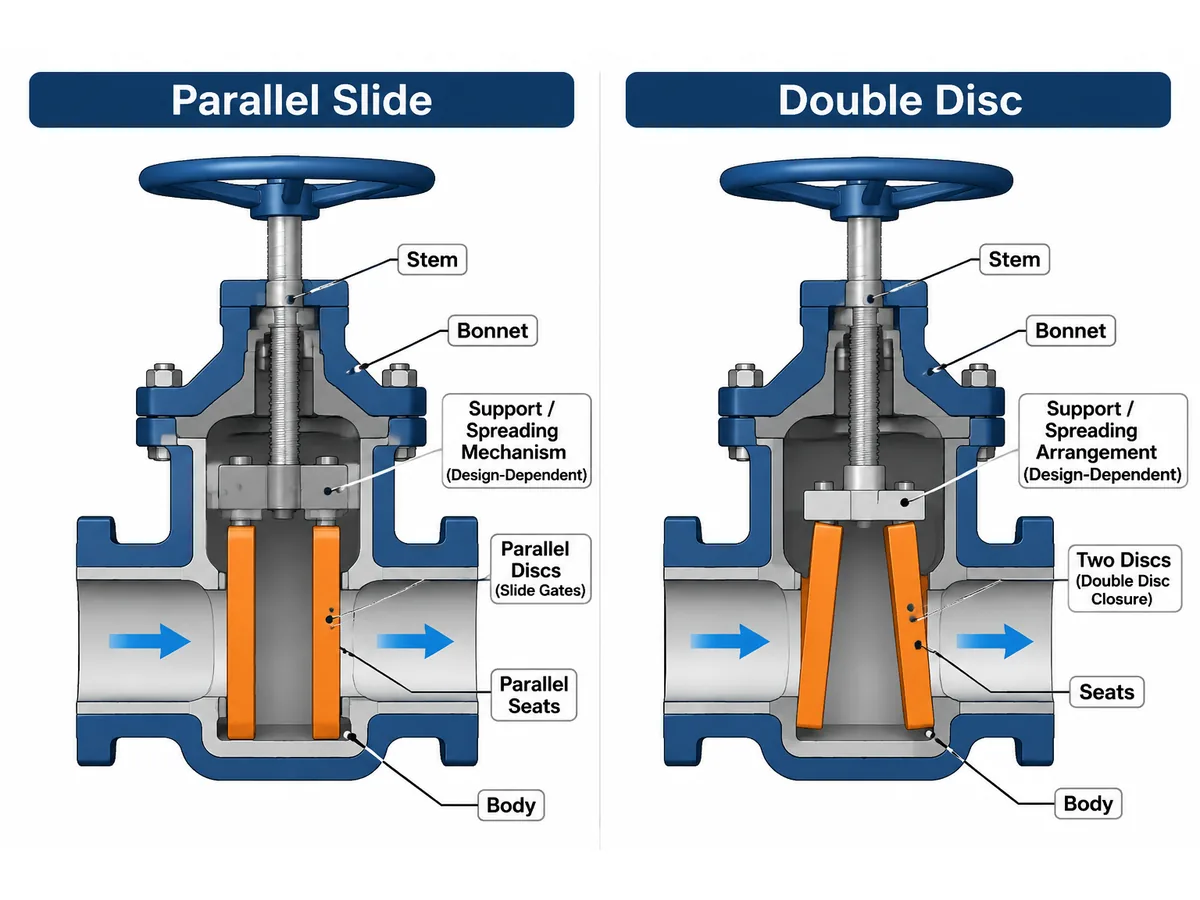
Classification note: “Parallel slide” describes a parallel-seat closure arrangement, while “double disc” describes a two-disc closure configuration. These terms can overlap in some designs, but they are not interchangeable universal labels. Confirm the actual disc support, spreading mechanism and seating arrangement from the manufacturer’s sectional drawing.
Parallel Gate Valve Types
Parallel gate valves use parallel seating surfaces rather than the inclined seating geometry of conventional wedge gate valves. The seating force may be generated by springs, mechanical spreading arrangements, fluid pressure or a combination of these mechanisms, depending on the design.
Parallel Slide Gate Valve
A parallel slide gate valve uses parallel seating surfaces and a design-specific arrangement to maintain contact between the closure element and seats. Some designs use two discs and a spreading or spring-assisted mechanism; other parallel-seat constructions differ. Confirm the actual disc configuration, support, seating-force mechanism and permitted flow direction from the manufacturer’s sectional drawing.
- Parallel seating geometry.
- No conventional tapered wedge action.
- Design-dependent disc spreading or pressure-assisted seating.
- Potential advantages in applications subject to thermal transients, where supported by the design.
Applicazioni tipiche: selected steam systems, power generation, high-temperature process services and applications specified for parallel-seat construction.
Engineering consideration: Parallel slide valves are not one universal design. Flow direction, differential pressure, disc configuration and manufacturer instructions must be confirmed before installation.
Double Disc Gate Valve
A double disc gate valve uses two separate closure discs rather than a single solid wedge. The discs may be supported or spread apart by a mechanical arrangement, allowing them to contact the respective seats.
- Two-disc closure construction.
- Design-dependent spreading mechanism.
- Independent seating contact in applicable arrangements.
- Internal geometry that differs from a one-piece wedge.
Applicazioni tipiche: selected industrial isolation and steam or process services where the specified double-disc arrangement is appropriate.
Engineering consideration: Double-disc describes closure construction; it does not guarantee a particular pressure rating or sealing performance. Confirm the disc-support mechanism, seat arrangement and pressure-assisted sealing behavior from the manufacturer’s drawings.
Pipeline Gate Valve Types
Pipeline gate valves are designed around pipeline isolation requirements, including bore continuity, pigging, sealing arrangements and cavity management.
Valvola a saracinesca a passaggio totale
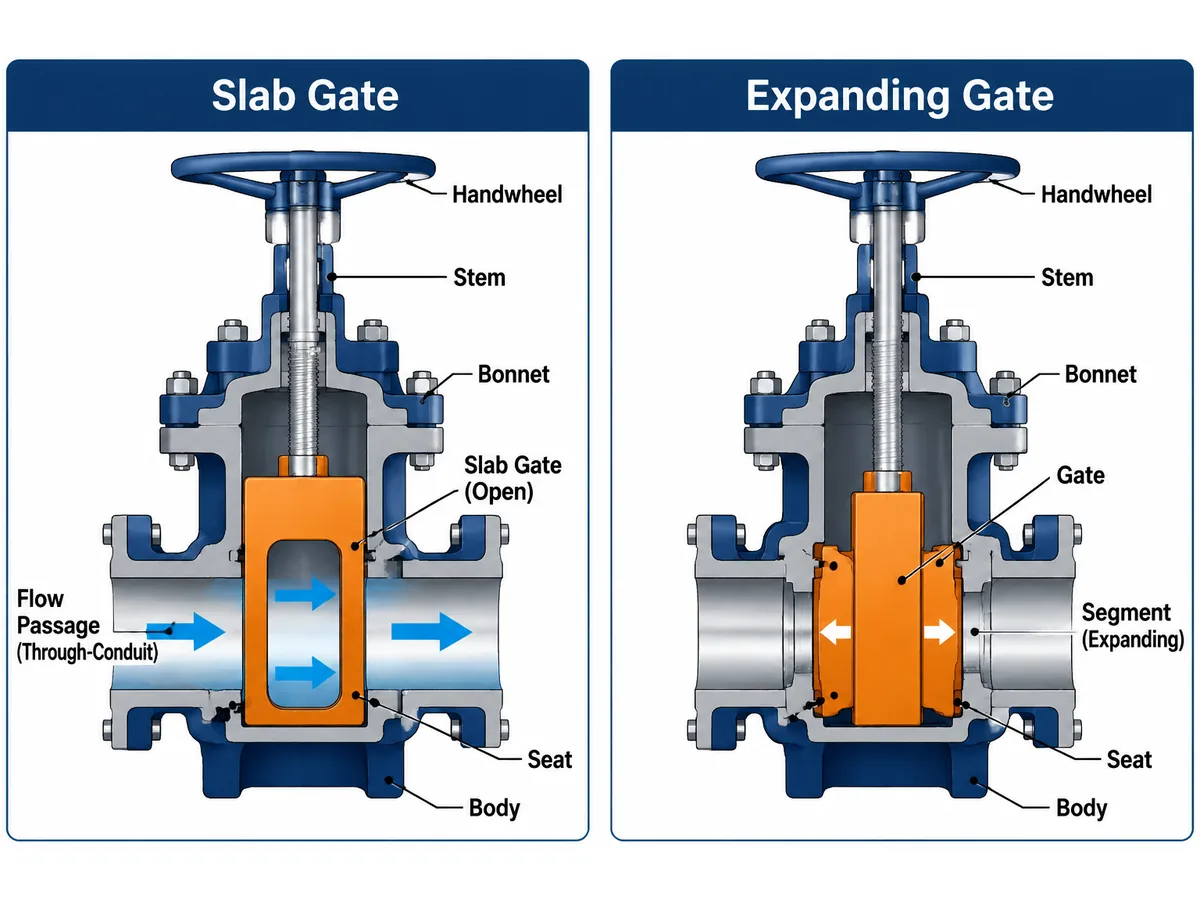
A slab gate valve generally uses a single flat gate. In a through-conduit design, an opening through the gate aligns with the pipeline bore when fully open, creating a substantially continuous passage. Not every valve sold as a slab gate has the same bore, seat-pocket or cavity arrangement.
- Single slab-type gate.
- Through-conduit flow path in full-bore configurations.
- Application-specific seat and sealing arrangements.
- Suitable for specified pipeline isolation duties.
Applicazioni tipiche: oil and gas pipelines, pipeline systems requiring pigging and selected transmission or process isolation services.
Engineering consideration: Not every slab gate valve has identical sealing or cavity-relief arrangements. Verify the actual minimum bore and internal profile, seat-pocket arrangement, cavity pressure management, flow direction and the required isolation function. Pigging compatibility must be confirmed against the specified pig dimensions and the pipeline geometry; the term “slab gate” alone does not establish piggability.
Pipeline receiving example: A nominally full-bore valve can still conflict with a pig if the actual minimum bore, port alignment or internal projections differ from the pipeline requirement. Compare the approved sectional drawing and dimensional records with the pig envelope and pipeline specification before acceptance.
Valvola a saracinesca ad espansione
An expanding gate valve uses a gate and a separate segment that are mechanically expanded against the seats during the closing sequence. The exact expansion sequence, seat loading and cavity behavior depend on the design; do not infer double-block-and-bleed performance from the product name alone.
- Gate-and-segment construction.
- Mechanical expansion during closure.
- Seating contact generated by the expansion mechanism.
- Design-dependent double-block-and-bleed capability.
Applicazioni tipiche: pipeline isolation, oil and gas transmission and applications requiring a specified mechanical seating arrangement.
Engineering consideration: An expanding gate valve is mechanically different from a conventional slab gate valve. Evaluate operating torque, internal mechanism, cavity arrangement and pressure-management requirements for the actual service.
Classification note: “Knife gate” describes the blade-like gate geometry and intended solids-handling function. It does not, by itself, define whether the valve uses parallel seats, a resilient seat, metal seats, or a particular pressure rating. Confirm the seat construction and rated service from the datasheet.
Knife Gate Valves
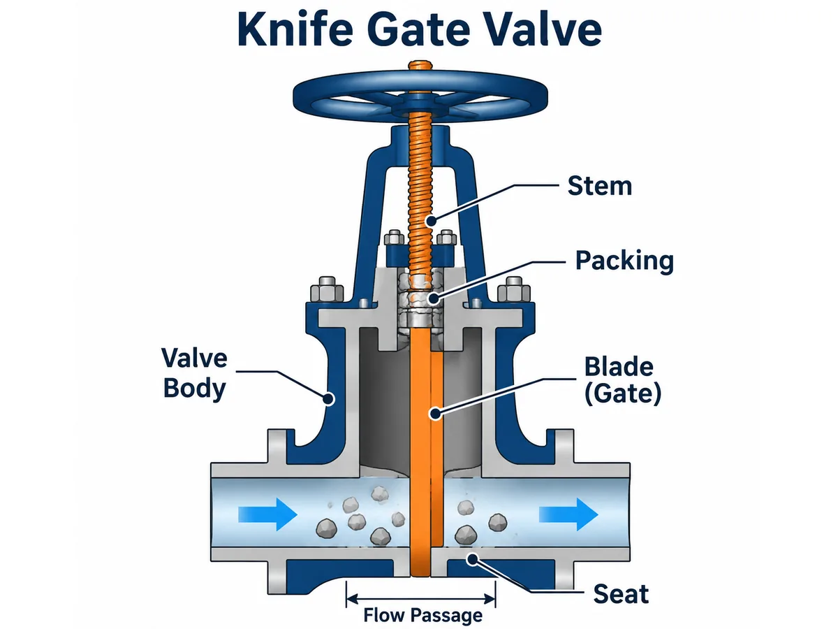
A knife gate valve uses a relatively thin, blade-like gate intended to move through media that may contain suspended solids, fibres or other difficult materials. Knife gate describes the closure geometry and duty concept; it does not establish a universal pressure rating, seat arrangement or leakage capability.
- Thin blade-like gate.
- Compact face-to-face construction in many designs.
- Application-specific seat and packing arrangements.
- Available in different body and connection configurations.
Applicazioni tipiche: mining and mineral processing, pulp and paper, wastewater treatment, slurry handling and industrial solids-handling systems.
Engineering consideration: A knife gate valve should not automatically be selected for every slurry application. Pressure differential, particle size, solids concentration, abrasiveness, seat design, flushing requirements and leakage acceptance criteria affect suitability. Distinguish between unidirectional and bidirectional sealing designs.
Slurry-service review example: If solids accumulate near the seat or the valve cannot complete its stroke, check particle size and concentration, differential pressure, flushing provisions, seat material and the specified operating cycle. The symptom alone does not prove that a knife gate is the correct or incorrect design.
Gate Valve Types by Stem Arrangement
Stem arrangement is an independent classification dimension and can be combined with different gate and bonnet designs.
Rising Stem Gate Valve
A rising stem gate valve has a stem that moves upward as the gate opens. The rising stem provides a visible indication of valve position, although sufficient vertical installation clearance is required.
- Visual position indication.
- In common OS&Y arrangements, stem threads are outside the pressure boundary.
- Access for inspection and lubrication of exposed threads.
- Additional overhead space is required.
- Exposed threads may need environmental protection.
Non-Rising Stem Gate Valve
A non-rising stem gate valve operates without the stem extending significantly above the valve during opening. The stem rotates while transmitting movement to the gate through an internal threaded arrangement.
- Reduced installation height.
- Useful where overhead clearance is limited.
- Less direct visual indication of gate position.
- Internal stem threads may contact the process medium, depending on the design.
- Corrosion, solids and lubrication conditions require consideration.
The choice between rising and non-rising stems should consider installation space, process fluid, maintenance access and operating requirements.
Gate Valve Types by Bonnet Construction
Bonnet construction affects pressure containment, sealing, maintenance and the overall valve assembly. It does not determine the gate geometry.
Bolted Bonnet Gate Valve
A bolted bonnet uses bolting to connect the bonnet to the valve body, with a gasket or another specified sealing arrangement. It is a common construction for many industrial gate valves.
Pressure Seal Bonnet Gate Valve
A pressure seal bonnet uses internal pressure to energize the bonnet sealing arrangement. This design is used in selected higher-pressure applications, subject to the applicable design and pressure-temperature requirements.
Welded Bonnet Gate Valve
A welded bonnet uses a welded body-to-bonnet connection. It may be specified where a permanent pressure-containing joint and a particular maintenance philosophy are required.
Important distinction: A wedge gate and a parallel gate are different closure designs; bolted, pressure seal and welded bonnets are different body-to-bonnet arrangements. These classifications can coexist on one valve.
Gate Valve Design Standards and Inspection Testing
Design standards and inspection or pressure-testing standards serve different purposes. The applicable documents depend on valve type, size, pressure class, end connection, service and the project purchase specification. The standards below are common reference points, not a universal checklist for every gate valve.
| Standard | General scope relevant to gate valves | How to use it in an RFQ |
|---|---|---|
| API 600 | Steel gate valves with flanged and butt-welding ends and bolted bonnets. | Confirm that the valve construction and service fall within the standard’s scope and the specified edition/addenda. |
| API 602 | Compact gate, globe and check valves for petroleum and natural gas industries, DN 100 (NPS 4) and smaller. | Check size, pressure class, material and end-connection scope before specifying. |
| API 6D | Pipeline and piping valves, including gate valves, for the relevant petroleum and natural gas applications. | Use where the pipeline valve application and project specification call for API 6D; verify current addenda and errata. |
| ISO 14313:2025 | Pipeline valves for oil and gas industries; the 2025 edition supplements API 6D, 25th edition, as stated by ISO. | Confirm whether the project specifies ISO 14313:2025, API 6D, or both, and apply the stated supplement relationship. |
| API 598 | Valve inspection, examination and pressure-test requirements for listed valve types, including gate valves. | Specify the required inspection and test standard separately from the valve design standard. |
The API catalog identifies API 600 as “Steel Gate Valves—Flanged and Butt-welding Ends, Bolted Bonnets” and API 602 as covering gate, globe and check valves DN 100 (NPS 4) and smaller in the petroleum and natural gas industries. The API catalog displays standards at different development stages; verify the currently published edition, addenda and errata in the API Publications Store when the purchase specification is issued. ISO identifies ISO 14313:2025 as Edition 3, published in June 2025, and states that it supplements API 6D, 25th edition (2021).after
Design versus testing: API 600, API 602 and API 6D address valve design or product requirements within their respective scopes. API 598 addresses inspection and testing. A pressure-test standard does not, by itself, establish that a valve design complies with a design standard. Always identify the edition, addenda/errata, acceptance criteria and any project supplements in the purchase specification. Confirm the latest applicable revision with the standards body and purchaser before ordering.
Official references: API standards updates, API Digital Catalog, ISO 14313:2025, e DLA record for API 598 scope.
Gate Valve Types Comparison Table
| Gate valve type | Closure construction | Applicazione tipica | Main selection consideration |
|---|---|---|---|
| Solid wedge | One-piece rigid wedge | General isolation | Thermal distortion and binding |
| Flexible wedge | One-piece flexible wedge | Steam and thermal cycling | Flexure and thermal design |
| Split wedge | Two-piece wedge | Selected gas and liquid service | Segment alignment and mechanism |
| Parallel slide | Parallel closure discs | Selected steam and process service | Seating mechanism and flow direction |
| Double disc | Two closure discs | Specified industrial isolation | Disc spreading arrangement |
| Slab gate | Single slab gate | Isolamento di linea | Bore continuity and pigging |
| Expanding gate | Expanding gate and segment | Isolamento di linea | Mechanical expansion and cavity design |
| Coltello | Thin blade-like gate | Slurry and solids handling | Pressure differential and seat design |
This table provides an initial screening framework. It does not replace manufacturer drawings, technical datasheets or project-specific engineering review.
How to Choose the Right Gate Valve Type
Selecting a gate valve requires more than identifying the nominal size and pressure class. Review the following inputs before finalizing the construction. For a broader engineering decision process covering application inputs and specification review, see the Guida alla selezione delle valvole a saracinesca.
1. Define the Medium
- Fluid name and composition.
- Liquid, gas or multiphase condition.
- Suspended solids and particle size.
- Corrosive or abrasive properties.
- Potential for deposits, scaling or coking.
2. Confirm Pressure and Temperature
Identify normal and design pressure and temperature, including startup, shutdown and transient conditions. Thermal cycling can influence the selection between rigid wedge, flexible wedge and parallel-seat arrangements. Do not select a design from the temperature label alone: review the full temperature range, cycling frequency, body and gate materials, seat geometry, differential pressure and the manufacturer-approved operating envelope.
3. Determine the Required Flow Passage
Confirm whether the application requires a standard gate valve bore, full-bore through-conduit construction, pigging compatibility or another specific flow-path requirement.
4. Review Sealing Requirements
Specify the required shut-off direction, allowable leakage, bidirectional or unidirectional sealing, seat and gate materials, and pressure-test acceptance criteria.
5. Review Stem and Bonnet Construction
Check installation height, stem exposure, maintenance access, operating mechanism and pressure-containing joint design.
6. Confirm Operation and Documentation
Identify manual or actuated operation, operating frequency, torque requirements, inspection scope and required manufacturing records. Review the available gate valve product category when defining the commercial configuration. Applicable design and testing standards should be confirmed against the project specification. See the industrial valve standards guide for a starting point.
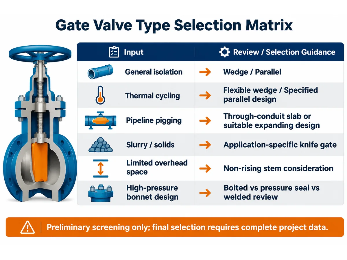
Preliminary Gate Valve Type Screening: When to Consider Each Design
Use this table to narrow the design discussion before requesting a quotation. It is not a universal recommendation: the same service label can involve different pressure, temperature, solids and shut-off conditions.
| Service or project condition | Designs to investigate | Why they may be considered | Do not decide until you verify |
|---|---|---|---|
| General on/off isolation in a clean process line | Solid wedge; flexible wedge; specified parallel design | These are established isolation configurations with different seating geometries. | Pressure-temperature rating, medium compatibility, seat leakage requirement and thermal cycle. |
| Frequent or significant temperature cycling | Flexible wedge or a manufacturer-specified parallel-seat design | Closure geometry and seating mechanism may accommodate particular thermal movements. | Actual body and trim materials, transient temperatures, design details and manufacturer limits. |
| Pipeline requiring pig passage | Full-bore through-conduit slab or another specifically piggable pipeline design | A suitably dimensioned through-conduit bore can maintain passage continuity when fully open. | Minimum bore, bore alignment, seat-pocket arrangement, pig dimensions and pipeline specification. |
| Pipeline isolation with specified mechanical seat expansion | Expanding gate | The gate-and-segment mechanism can generate mechanical seating contact. | Operating mechanism, cavity pressure behavior, isolation/bleed requirement and maintenance procedure. |
| Slurry, fibres or suspended solids | Application-specific knife gate; other solids-service designs where appropriate | Blade geometry and body/seat arrangements may be configured for solids-handling duties. | Solids concentration, particle size, abrasiveness, pressure differential, flushing and leakage acceptance. |
| Restricted overhead clearance | Non-rising stem arrangement | Can reduce the vertical envelope compared with a rising-stem configuration. | Position indication, internal thread exposure, access for maintenance and stem/medium compatibility. |
Screening rule: If the project specification requires a defined leakage class, double-block-and-bleed function, piggability, fire-safe design or sour-service compliance, confirm the exact design standard, test basis and documentary evidence. A generic valve-type name does not establish compliance.
Failure Modes and Field Verification Points
When reviewing an existing valve or evaluating a proposed design, connect each observed symptom to a verification step. Do not assume that one symptom proves one failure mechanism.
| Observed issue | Possibili cause | What to verify | Specification or maintenance response |
|---|---|---|---|
| High operating torque or valve will not travel fully | Thermal distortion, deposits, corrosion, stem/thread damage, actuator or gearbox issue, excessive differential pressure | Operating conditions at the time of failure, travel history, stem condition, actuator sizing basis and internal inspection findings | Confirm allowable operating differential pressure and torque basis; define cleaning, inspection or repair scope. |
| Leakage through the closed valve | Seat damage, embedded solids, erosion, corrosion, misalignment or unsuitable shut-off specification | Leakage direction, test medium, test pressure, duration, acceptance criterion and seat condition | Specify the required leakage acceptance and test standard; assess seat/trim materials against the medium. |
| External leakage at stem area | Packing wear, incorrect packing installation, stem surface damage or unsuitable operating conditions | Packing arrangement, stem finish/condition, gland configuration and applicable emission requirement | Define packing material and inspection/maintenance requirements; request evidence if fugitive-emission qualification is specified. |
| Unstable operation or repeated damage in slurry service | Solids accumulation, abrasion, particle bridging, inadequate flushing or unsuitable seat geometry | Particle size and concentration, velocity, differential pressure, flushing arrangement and damage pattern | Reassess valve construction and service data; do not select a knife gate solely from the word “slurry”. |
| Pipeline pig does not pass as expected | Reduced bore, misalignment, protruding components or incorrect valve configuration | Certified bore dimensions, internal profile, valve orientation and pig envelope | Include piggability and minimum clear-bore requirements in the datasheet and drawing review. |
These are troubleshooting prompts, not a substitute for site isolation, depressurization, approved maintenance procedures or inspection by qualified personnel.
Evidenze del fornitore da richiedere prima dell'approvazione tecnica
Supplier evaluation should compare documents against the purchase specification rather than relying on a product description or a general statement of compliance.
| Area di revisione | Evidence to request, where applicable | What the buyer should check |
|---|---|---|
| Design and construction | GA drawing, sectional drawing, datasheet and bill of materials | Gate construction, bore, stem arrangement, bonnet joint, flow direction and maintainability. |
| Pressure-temperature suitability | Applicable rating data and design documentation | Rating covers the specified material, size, class and operating/design temperature. |
| Materials and traceability | Material list, material test certificates and traceability records as specified | Material grades and traceability match the approved datasheet and purchase requirements. |
| Ispezione e collaudo | Inspection and Test Plan, test procedure and test reports required by the order | Test type, acceptance criteria, sampling, witness/hold points and report traceability. |
| Special service requirements | Qualification or test evidence specifically required by the project | Evidence covers the exact valve design, size range, materials and service conditions; do not infer qualification from a generic certificate. |
| Deviations and exceptions | Completed deviation list and technical clarification register | Every exception is visible, resolved and approved before order placement. |
A document list is a procurement requirement, not proof that a supplier already holds every record or qualification. Confirm availability, scope, revision, traceability and applicability for the exact offered valve before technical approval.after
Confine delle prove: This article does not establish that Raymon Valve holds any particular certificate, qualification or test approval. Availability and scope of documents must be confirmed for the specific offered valve and purchase order.
How to Compare Gate Valve Quotations on a Like-for-Like Basis
Two quotations may use the same nominal size and pressure class but describe different internal constructions or documentation scopes. Normalize the following items before comparing price and delivery.
| Campo di confronto offerta | Bidder A | Bidder B | Buyer normalization check |
|---|---|---|---|
| Gate type and internal mechanism | As quoted | As quoted | Are the closure construction and seating mechanism equivalent? |
| Size, class and end connection | As quoted | As quoted | Same nominal size, rating basis, facing and connection standard? |
| Body, gate, seat and stem materials | As quoted | As quoted | Same material grades, overlays/coatings if specified, and traceability scope? |
| Operation and operating data | As quoted | As quoted | Same operator type, operating conditions and torque/force assumptions? |
| Leakage and testing | As quoted | As quoted | Same test standard, test conditions and acceptance criteria? |
| Ispezione e documentazione | As quoted | As quoted | Same ITP, certificates, NDE/PMI and third-party scope? |
| Deviations, exclusions and delivery | As quoted | As quoted | Are exclusions, spares, packing, delivery basis and exceptions comparable? |
Record unresolved differences in a technical clarification or deviation register. Do not treat a lower-priced offer as technically equivalent until its construction, testing and documentation scope have been normalized.
Common Gate Valve Selection Mistakes
| Common mistake | Potential consequence | Recommended review |
|---|---|---|
| Using a gate valve for continuous throttling | Vibration and accelerated seat wear | Confirm isolation versus control duty |
| Selecting a rigid wedge without thermal review | Potential binding | Review temperature cycles and body deformation |
| Treating slab and expanding gates as identical | Incorrect specification | Review sectional drawings and seating mechanism |
| Selecting a knife gate only because solids are present | Unsuitable pressure or sealing performance | Review solids and pressure conditions |
| Ignoring stem clearance | Installation and maintenance problems | Check installation envelope |
| Specifying only nominal size and class | Incomplete technical quotation | Submit complete service data |
Gate Valve Drawing Review Checklist
Before approving a technical bid or manufacturing drawing, review the sectional drawing and general arrangement together. The drawing should make the specified construction verifiable rather than relying on a product name alone.
| Drawing item | What to verify | Perché è importante |
|---|---|---|
| Gate and disc geometry | One-piece wedge, flexible wedge, split wedge, parallel discs, slab or expanding segment as specified. | Confirms the actual closure construction. |
| Disposizione della sede | Seat orientation, seat-ring construction, replaceability and stated sealing direction. | Helps assess shut-off function and maintenance. |
| Flow passage | Minimum bore, port alignment, internal projections and any specified through-conduit profile. | Important for pressure loss, cleaning and pig passage requirements. |
| Stem and yoke | Rising/non-rising arrangement, thread location, stem travel and available operating clearance. | Checks installation and access constraints. |
| Bonnet joint | Bolted, pressure seal or welded construction and the specified sealing arrangement. | Confirms pressure-boundary configuration. |
| Cavity and drain/vent features | Pressure communication, cavity relief or drain/vent provisions where specified. | Important for the defined isolation and pressure-management philosophy. |
| Actuation interface | Handwheel/gearbox/actuator interface, stem nut and required operating envelope. | Prevents interface and access conflicts. |
This is a purchaser’s review checklist, not a substitute for the applicable design code, approved drawings or manufacturer calculations.
Seat Leakage vs. Stem Leakage
Leakage location changes the inspection path. Internal seat leakage is flow passing through the closed valve, while external stem leakage is fluid escaping to the atmosphere around the stem packing or stem seal. They should not be diagnosed or reported as the same failure.
| Condizione osservata | Possible areas to investigate | Evidence to record |
|---|---|---|
| Internal leakage across a closed valve | Seat/gate damage, embedded particles, corrosion, erosion, misalignment, incorrect operating position or unsuitable differential-pressure conditions. | Test medium, pressure, direction, duration, leakage measurement and acceptance criterion. |
| External leakage around the stem | Packing condition, gland adjustment, stem surface damage, stem runout, installation and material compatibility. | Leak location, operating state, process conditions, packing arrangement and maintenance history. |
| Leakage at body-bonnet joint | Gasket/seal condition, bolting, joint surface, assembly procedure or pressure/temperature excursion. | Joint design, assembly records, inspection findings and operating history. |
Limite di sicurezza: Do not loosen packing, bonnet bolting, drains or vents on a pressurized valve as a troubleshooting shortcut. Isolation, depressurization, draining, verification of zero energy and the site’s approved permit-to-work procedure must precede intrusive inspection or maintenance.
Supplier Technical Clarification Questions
When comparing quotations, use written clarifications to expose differences that may be hidden by identical nominal size and pressure-class descriptions.
- Which exact gate and seat construction is offered? Please provide a sectional drawing identifying the gate, discs, segment and seat arrangement.
- Is the valve intended for unidirectional or bidirectional shut-off, and what test basis supports the stated leakage acceptance?
- What is the minimum flow bore, and is the offered configuration compatible with the project’s pig dimensions and pipeline geometry?
- How are cavity pressure and any specified drain, vent or pressure-relief functions addressed?
- What are the body, gate, seat, stem and packing materials, and what process-fluid compatibility basis is used?
- Which design and inspection/testing standards and editions are included? List deviations and exclusions separately.
- What operating torque or thrust data and actuator interface information are included, and what assumptions were used?
- Which drawings, material records, inspection reports and pressure-test records will be supplied with the order?
Gate Valve RFQ Checklist
Before requesting a quotation, provide the following information where applicable.
Basic Valve Information
For pressure class or PN, state the applicable rating standard and material group where required. Class 150, 300, 600 and similar designations are not fixed pressure values independent of material and temperature. Provide both normal and design pressure/temperature, plus the maximum differential pressure relevant to operation and shut-off.
- Valve tag number and quantity.
- Gate valve type and construction.
- Nominal size and pressure class.
- End connection and applicable dimensional standard.
Process Conditions
- Medium and composition.
- Normal and design pressure.
- Normal and design temperature.
- Pressione differenziale.
- Solids, abrasiveness and corrosion conditions.
Construction Requirements
- Body and bonnet material.
- Gate and seat material.
- Stem and packing requirements.
- Rising or non-rising stem.
- Bolted, pressure seal or welded bonnet.
- Manual or actuated operation.
Quality and Documentation
- Applicable design and testing standards.
- Inspection and Test Plan requirements.
- Material certificates and traceability requirements.
- NDE and PMI requirements where specified.
- Pressure and seat leakage test requirements.
- Third-party inspection and documentation requirements.
Additional Project Inputs to Clarify
- Normal, minimum and maximum operating conditions, including startup and shutdown cases.
- Maximum differential pressure during opening and closing, where relevant.
- Required flow direction, isolation direction and whether double-block-and-bleed is specified.
- For slurry: solids concentration, particle-size range, abrasiveness and flushing/cleaning arrangement.
- For piggable pipelines: required clear bore, pig dimensions and any internal profile restrictions.
- Installation orientation, available stem/actuator clearance and access for maintenance.
- Required marking, packing, preservation, export documentation and delivery conditions.
If a value is not yet available, mark it as “to be confirmed” rather than leaving it ambiguous. The supplier should list assumptions and deviations explicitly. The final specification should identify the exact valve configuration and any technical deviations from the purchase specification.
Engineering Notes, Assumptions and Limits
- Scopo: This page is a preliminary guide to gate valve construction, application screening and RFQ preparation.
- Classification: Gate/disc construction, stem arrangement, bonnet construction and actuation are separate design dimensions and may be combined.
- Performance: No universal pressure, temperature, leakage, torque or service-life value is assigned to a valve type in this article.
- Materials: Material and seat compatibility must be assessed against the actual medium, concentration, temperature, pressure and project requirements.
- Standards: Applicable design, dimensional, testing and special-service requirements must be identified from the purchase specification and checked for current edition and scope.
- Evidenza: Drawings, datasheets, material records, inspection plans and test reports should be reviewed for the exact offered configuration.
- Approval: Final selection requires project-specific engineering confirmation and approval under the buyer’s procedures.
Content attribution: Raymon Valve Technical Content Team. This is general technical information, not a project-specific engineering approval.
Domande frequenti
What are the main types of gate valves?
The main types include solid wedge, flexible wedge, split wedge, parallel slide, double disc, slab, expanding gate and knife gate valves. They differ in closure construction, seating mechanism and application.What is the difference between solid wedge and flexible wedge gate valves?
A solid wedge uses a rigid one-piece closure element, while a flexible wedge incorporates designed flexibility to accommodate certain seating and thermal movements.What is the difference between parallel slide and wedge gate valves?
Wedge gate valves use inclined seating surfaces, whereas parallel slide designs use parallel seating surfaces and a different seating-force mechanism.What is a slab gate valve?
A slab gate valve uses a single slab-type gate. Through-conduit designs provide a continuous bore when fully open and may be used in pipeline systems requiring pigging.What is an expanding gate valve?
An expanding gate valve uses a gate and segment that mechanically expand against the seats during closure.Are knife gate valves suitable for slurry service?
They can be suitable for selected slurry and solids-handling duties. Pressure differential, particle properties, seat design and leakage requirements must be checked.What is the difference between rising stem and non-rising stem gate valves?
A rising stem extends upward during opening, while a non-rising stem rotates without the same vertical movement. Installation clearance and maintenance requirements are key selection factors.Can gate valves be used for throttling?
Gate valves are generally designed for isolation rather than continuous throttling. Partially open operation can cause vibration, high local velocities and seat or gate erosion.How do I choose the right gate valve type?
Start with the medium, pressure, temperature, solids content, required shut-off performance and installation conditions. Then confirm gate construction, stem arrangement, bonnet design, materials and testing requirements against the complete project specification.
Conclusione
Different gate valve types solve different isolation requirements. Solid and flexible wedge designs, split wedges, parallel slide arrangements, slab and expanding pipeline gates, and knife gate valves should be evaluated according to their actual closure mechanisms and service conditions.
For industrial projects, the best selection is not determined by valve type alone. Process conditions, pressure-temperature limits, material compatibility, seat design, operating method, maintenance access and inspection requirements must all be considered.
Request a Gate Valve Selection Review
Send your gate valve datasheet or RFQ so the requested construction can be reviewed against the stated service conditions. Include the valve type (if specified), size and class, medium, normal and design pressure/temperature, differential pressure, end connection, body and trim materials, shut-off/leakage requirement, stem and bonnet arrangement, operation method, and required standards, tests and documentation.
If any project data is still pending, identify the open items. Technical deviations, assumptions and required supplier documents should be clarified before technical approval. Final valve selection and product compliance must be confirmed against the approved project datasheet, purchase specification and manufacturer documentation.Contatta Raymon Valve
You can also review gate valve product range e sulla company profile.
 Italian
 English
 German
 Arabic
 French
 Spanish
 Portuguese
 Russian