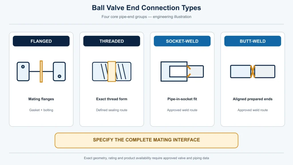
Engineering illustration comparing flanged threaded socket-weld and butt-weld Ball Valve piping interfaces

Ball Valve End Connection Types: How to Specify the Complete Piping Interface

The four core industrial Ball Valve pipe-end groups are flanged, threaded, socket-weld and butt-weld. Each uses a different mating interface and therefore requires different installation, inspection and replacement planning. Wafer or flangeless patterns are better treated as special flange-mounted arrangements, not another pipe-end preparation parallel to threading or welding. No connection is universally best: the shortlist depends on the piping standard, pipe dimensions, pressure-temperature cases, medium, leakage consequence, field-work controls, maintenance strategy and approved valve drawing.

Interface Approval Sequence

Use the connection name to start the review, then close the complete installed interface before technical approval.

  1. Identify the interface.Record the end type on each side, piping standard, pipe dimensions and project design cases.
  2. Define the installed joint.Specify the mating flange system, thread and seal, or socket/butt-weld geometry and field-work route.
  3. Request controlled evidence.Obtain the exact supplier GA or end-detail drawing, revision, datasheet and applicable test/document scope.
  4. Record assumptions and deviations.Mark each field CONFIRMED, ASSUMED ou OPEN, and assign its decision owner.
  5. Approve or Hold.Release the interface only when compatibility, installation, inspection and replacement responsibilities are closed.

Featured illustration: Conceptual comparison of flanged, threaded, socket-weld and butt-weld piping interfaces. Exact geometry, rating and product availability require the approved valve and piping data.

Seleção Rápida Gaveta

An end-connection label is only a starting point. Use the project condition to identify an initial direction, then hold approval until the complete interface is defined.

Project condition Initial direction Data still required Hold condition
The valve must be removed without cutting the pipe Review a flanged route Flange system, face-to-face, bolt and gasket access, pipe support and removal clearance The layout cannot separate the flanges or support the line safely
A compact connection is needed and field welding is not the selected route Review a threaded route within the project piping rules Exact thread form, sealing method, size, rating basis, external loads and service consequence The RFQ says only roscada, NPT ou BSP without a complete designation
The project uses selected small-bore welded piping Review a socket-weld route if permitted by the governing specification Pipe/end dimensions, fit-up, welding procedure, heat controls, examination and replacement plan Valve construction and field-welding requirements have not been reconciled
The piping philosophy calls for a permanent welded joint Review a butt-weld route Pipe OD and wall, end preparation, bore transition, welding/PWHT/NDE scope and cut-out strategy The mating pipe or end-detail drawing is missing
A short body must be mounted between mating flanges Review a verified wafer/flangeless configuration Compatible flanges, bolting, centering, sealing arrangement, face-to-face, support and product limits The body is assumed to fit any flange system
An existing valve must be replaced inside fixed pipework Start from the controlled existing interface Approved drawing, actual dimensions, end details, bore, operator envelope and deviations Nominal size and pressure class are the only matching fields
Leakage consequence, cycling or access restrictions are significant Compare all feasible routes through the project risk and inspection process Complete design cases, joint controls, responsible owners and acceptance evidence A connection is selected from a generic service label

This table does not approve a valve. Size and pressure class do not establish the thread, flange, weld preparation, installed joint, valve length or service suitability.
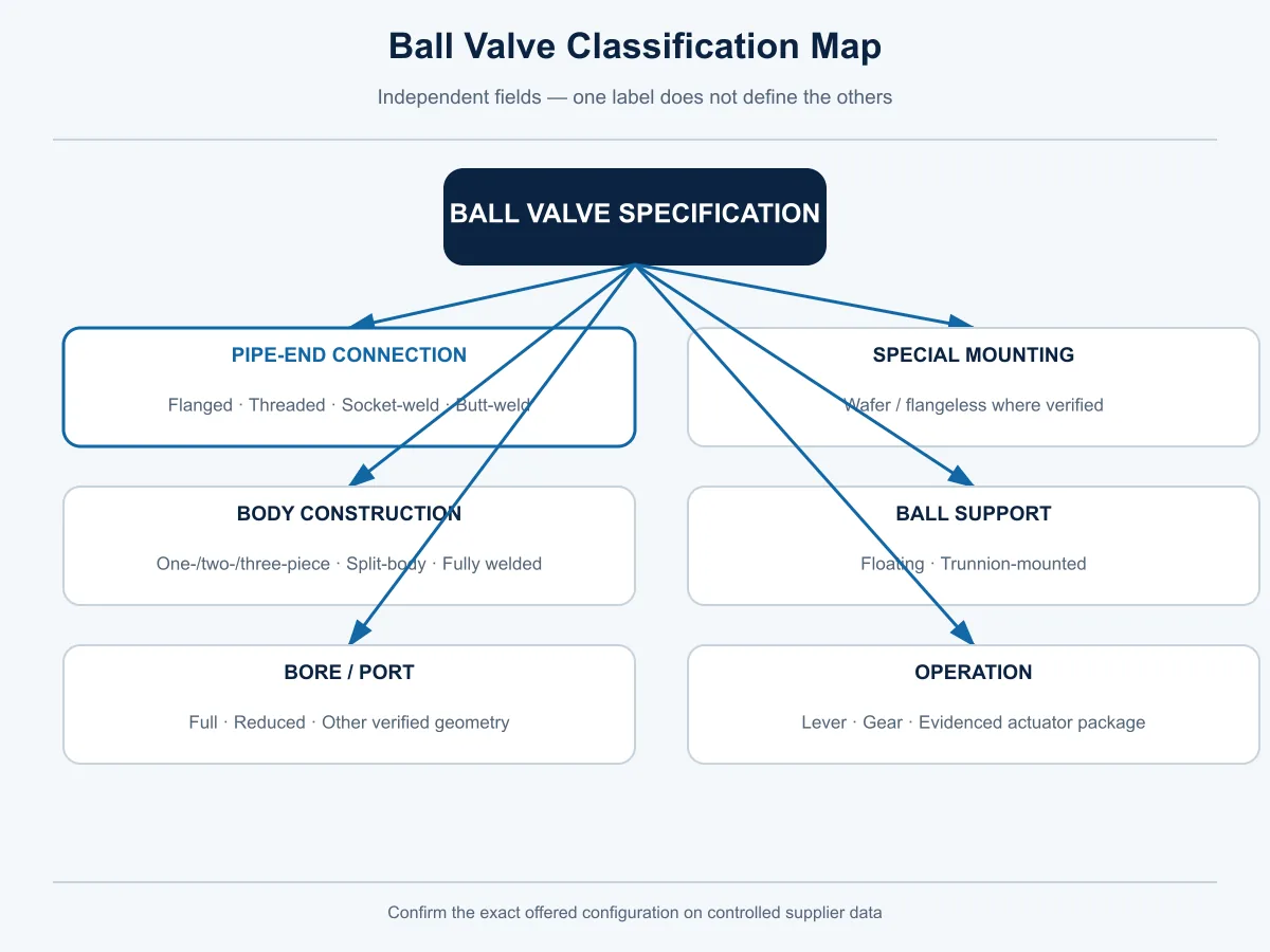
Ball Valve classification map separating end connection body construction ball support bore and operation
Classification axes are independent. A body-construction label does not define the pipeline end connection.

What Counts as a Ball Valve End Connection?

Ball Valve descriptions often mix several independent classification axes. That creates procurement errors because two valves can share an end connection while differing in body construction, ball support, bore, seats and operation.

Classification axis O que descreve Examples
Pipe-end connection How the valve mates with the piping Flanged, threaded, socket-weld, butt-weld
Special mounting arrangement How a compact body is held between or against flanges Wafer/flangeless or another verified pattern
Construção do corpo How the pressure-containing body is assembled One-piece, two-piece, three-piece, split-body, fully welded body
Suporte da esfera How the ball is supported Floating or trunnion-mounted
Bore/port Flow-passage geometry Full port, reduced port or another verified geometry
Acionamento How the valve is operated Lever, gear or an evidenced actuator package

A fully welded body is not the same statement as butt-weld ends. The first describes body construction; the second describes the interface to the piping. Likewise, a flanged valve is not automatically floating or trunnion-mounted, full port or reduced port, soft seated or metal seated.

For a broader selection sequence covering function, construction, bore, seats, materials, actuation and evidence, use the Guia de seleção de válvulas esfera. This article stays focused on the piping interface.

Why wafer or flangeless needs a separate category

A wafer or flangeless body is mounted between or against mating flanges rather than being prepared like a threaded, socket-weld or butt-weld pipe end. Within its stated scope, ASME B16.34 treats wafer or flangeless valves installed between or against flanges as flanged-end valves. That standards convention does not prove that a specific Raymon product falls within the standard or is available in a particular configuration.

For procurement, record wafer/flangeless as a special flange-mounted arrangement and verify the exact body, flange compatibility, bolting, centering, sealing arrangement, face-to-face, support and any directional or dead-end limitation on the approved model drawing.
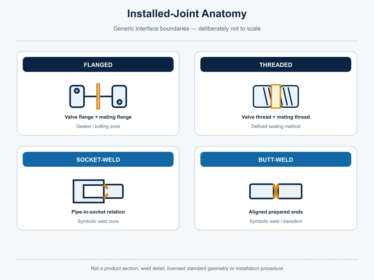
Simplified installed-joint anatomy for flanged threaded socket-weld and butt-weld Ball Valve ends
Generic interface anatomy only; not a product section, weld detail or installation procedure.

Flanged Ball Valve Ends

A flanged Ball Valve connects to mating pipe flanges through a joint system that includes the valve flange, pipe flange, facing, gasket, bolting and assembly controls. Writing flangeada in an RFQ does not define that system.

When a flanged route may be appropriate

A flanged route may enter the shortlist when the piping is already flanged, the project requires a detachable bolted interface, or planned valve removal is part of the maintenance strategy. It can support replacement without cutting the pipe, but only if the layout provides flange-separation space, bolt access, safe isolation and adequate pipe support.

The RFQ and drawing should identify:

  • the exact flange standard and project edition;
  • DN/NPS and rating designation;
  • flange series where applicable;
  • facing, finish, drilling and mating-flange details;
  • gasket and bolting requirements and supply ownership;
  • face-to-face dimension and installation envelope;
  • support and allowable-load assumptions; and
  • the intended removal path.

Hold approval if the valve is being forced into misaligned pipework, the mating flange system is unclear, gasket or bolting responsibility is missing, or nominal size is being used as proof of dimensional compatibility. The Guia de Seleção de Válvula Esfera Flangeada covers the deeper flange, gasket, bolting and interchangeability review.

Threaded Ball Valve Ends

A threaded connection depends on the exact thread system and its intended sealing mechanism. Roscada, BSP or a nominal size is not a complete interface definition. The RFQ must distinguish the adopted thread form, taper or parallel condition, designation, orientation where relevant, gauging or acceptance basis and sealing method.

When a threaded route may be appropriate

A threaded route may be considered for selected compact or small-bore piping where it is permitted by the governing project rules and field welding is not the chosen assembly method. Equipment and skid connections also require review of external loads, vibration, access, leakage consequence and the expected disassembly cycle.

Do not create a universal size, pressure or temperature cutoff from a generic guide. The acceptable boundary depends on the exact valve, thread, material, design cases, piping specification and jurisdiction.

The RFQ should state:

  • the exact thread standard, current project edition and designation;
  • size and male/female orientation where applicable;
  • whether the joint seals on the thread or on separate sealing faces;
  • the approved seal or sealant and its service review;
  • engagement, gauging and coating considerations;
  • wrenching instructions and protection of the valve body; and
  • piping support and the replacement strategy.

Hold the connection when NPT, BSPT and BSPP terminology is mixed, a tapered and parallel system is assumed to mate, sealant compatibility is open, or the valve body would absorb pipe misalignment. For a deeper thread-form and compact-valve review, see the Threaded Ball Valve Selection Guide.

Socket-Weld Ball Valve Ends

With a socket-weld end, the mating pipe enters a controlled socket and the installed joint is completed using the approved welding route. The end geometry, pipe dimensions, fit-up, welding procedure, heat input, inspection and valve construction form one approval package.

Socket-weld may enter the shortlist for selected small-bore welded piping when the governing piping code, project specification and offered valve scope allow it. The label does not by itself mean alta pressão, leak-free ou stronger than threaded.

The technical package should include:

  • socket dimensions and tolerance basis;
  • pipe OD, wall or schedule and material;
  • valve-end material and relevant heat-sensitive internal components;
  • fit-up and workmanship requirements;
  • approved WPS, personnel qualification and examination route;
  • preheat or PWHT requirements where applicable;
  • manufacturer installation instructions for protecting seats and seals; and
  • the cutting and replacement plan.

Hold approval when pipe/end dimensions are incomplete, the welding sequence has not been reconciled with the valve construction, cleanliness or crevice concerns remain unresolved, heat treatment may affect valve internals, or the inspection and replacement responsibilities are unclear.

Butt-Weld Ball Valve Ends

A butt-weld Ball Valve has prepared ends that are joined to the mating pipe through the approved project welding route. Solda de topo does not define the pipe schedule, end-preparation geometry, bore transition, material, consumable, WPS, PWHT or NDE.

A butt-weld route may be considered where the piping philosophy requires a permanent welded joint and the project accepts the installation, inspection and later replacement consequences. It should not be described as automatically best for buried, hazardous, high-pressure or high-temperature service. Those conclusions require the complete design cases and project acceptance criteria.

The RFQ and approved drawing should identify:

  • pipe OD, wall or schedule, material and tolerances;
  • the adopted end-preparation basis and exact geometry;
  • internal bore and transition details;
  • pigging, cleaning and internal-mismatch requirements where applicable;
  • WPS, qualifications, consumables, preheat, PWHT and examination ownership;
  • seat and seal protection during field work;
  • installation orientation and pipe support; and
  • cut-out length, spare strategy and replacement plan.

Hold the valve when the mating pipe data or end-detail drawing is missing, the bore transition is not reviewed, heat-treatment requirements conflict with the offered construction, NDE acceptance remains open, or maintenance planning assumes that the valve can be removed without cutting and rework.

Special Flange-Mounted and Application-Specific Interfaces

Wafer/flangeless patterns require verified mating-flange geometry, bolting, centering, gasket or seat interaction, face-to-face, body support and product-specific operating limitations. A compact body must not be assumed to fit every flange system.

Union, sanitary or clamp, grooved and other specialized interfaces also exist. They should be specified only when the exact offered product and application scope are supported by controlled data. A connection label alone does not establish hygienic design, clean-service suitability, quick maintenance or compatibility with a particular piping system.

A general Valve End Connection resource provides a cross-family view of engineered joints. The Ball Valve article remains responsible for the Ball-Valve-specific RFQ and interface decision.
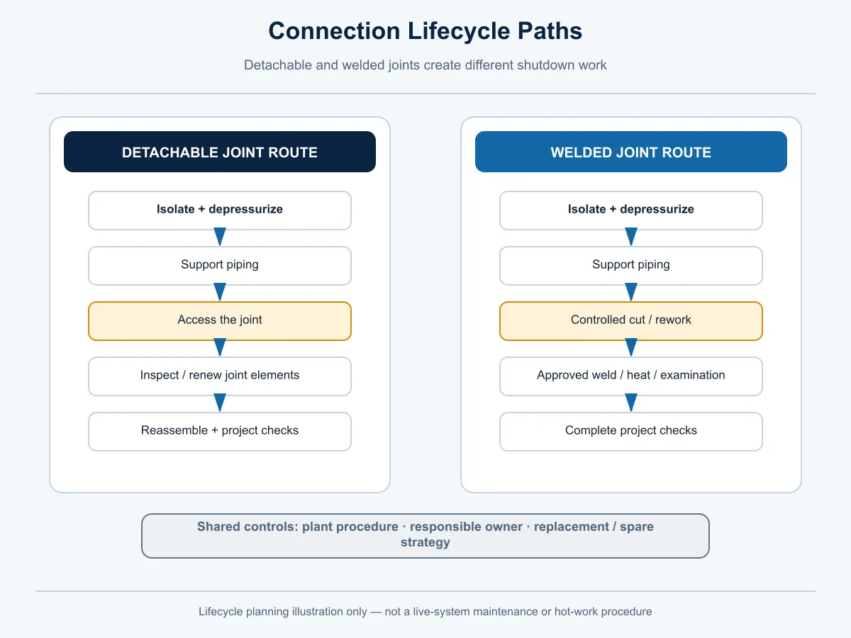
Ball Valve connection lifecycle paths for detachable and welded joint removal and replacement
Conceptual lifecycle comparison only. Site isolation, hot work, inspection and return to service follow approved plant procedures.

Removable and Permanent Joints Have Different Lifecycle Consequences

Purchase price does not describe the installed or replacement cost. The project must consider isolation, depressurization, support, access, hot-work controls, joint components, inspection and the spare strategy.

Conexão Installed joint elements Normal removal route Field controls Replacement implication Evidência exigida
Flangeada Mating flanges, gasket, bolting and assembled joint Isolate, support, unbolt and separate the flanges Bolt access, flange alignment, gasket/bolting control and pipe support May allow removal without cutting if the layout provides clearance Approved GA, flange data, joint specification and removal plan
Roscada Mating threads plus the specified sealing system Isolate, support and unthread where the layout permits rotation or disassembly Correct wrenching, thread condition, seal replacement and pipe loads Threads and seals may require inspection or rework before reuse Thread designation, sealing method and installation instructions
Encaixe para solda Socket fit-up and completed weld Normally cut or otherwise rework the piping under an approved plan Hot work, heat control, inspection and protection of valve internals Replacement scope must include field welding and examination End dimensions, WPS/inspection route and cut-out plan
Solda de topo Prepared pipe/valve ends and completed circumferential weld Normally cut and re-weld under an approved plan Fit-up, welding/PWHT/NDE, internal transition and pipe support Spare length, weld access and new examination may control shutdown work End drawing, pipe data, procedures and replacement plan

No route is maintenance-free. A welded joint removes detachable flange or thread elements at the valve ends, but it does not eliminate all possible external leakage locations or installation defects. A detachable joint can support removal, but it does not guarantee easy access or correct reassembly.

Check Installation and Interface Risks Before Approval

Connection selection is incomplete until the installed joint, surrounding pipework and later removal route have been reviewed together. Use the following hold points against the exact valve, drawing and site arrangement.

Revisar riscoConditions that make it relevantEvidence or check to requestHold point / decision owner
Flange misalignment or inaccessible boltingFixed pipework, limited separation space, heavy valve weight or restricted wrench accessLayout, support plan, bolt-removal envelope, flange alignment method and approved GAHold with piping/layout and construction owners
Thread damage, mixed thread systems or excessive assembly loadThread designation, taper/parallel form, sealing method or wrenching route is unclearExact thread designation, gauging basis, seal system, installation instructions and pipe supportHold with piping engineering and the valve supplier
Welding heat affects seats, seals or body conditionSocket-weld or butt-weld field installation, preheat or PWHT may applyApproved WPS, heat-control method, manufacturer installation limits, examination and post-work functional checkHold with welding, quality and manufacturer owners
Bore step or internal mismatch obstructs flow, cleaning or piggingPipe wall, valve passage, weld transition or device envelope differs from the assumed geometryControlled end-detail/passage drawing, pipe ID and actual cleaning or pig envelopeHold with pipeline/process and manufacturer owners
Pipe load or unsupported valve mass enters the endsThermal movement, nozzle misalignment, heavy operator or insufficient temporary support is possibleStress/support review, lifting plan, installation tolerances and allowable-load basis where requiredHold with piping/stress and layout engineering
Weld, thread or flange cleanliness is not controlledDebris, coating, sealant, weld residue or foreign material can enter the valve or jointPreservation, cleaning, flushing and inspection plan plus acceptance responsibilityHold with construction and quality owners
Replacement plan cannot be executed in the available shutdown windowFixed pipe length, no flange-separation space, hot-work restriction or inspection access constrains removalIsolation plan, cut-out/removal envelope, spare length, rework/NDE scope and return-to-service planHold with maintenance, operations and project engineering

This matrix identifies review points; it does not prescribe a project installation procedure or predict universal leakage, failure or service life.

Standards Must Be Assigned by Role

A purchase specification should not list standards without explaining what each one controls. The project edition, purchaser options and precedence must be stated.

Requirement role Candidate reference What it may define within scope O que não comprova
Valve design/rating context ASME B16.34 Pressure-temperature, materials, dimensions/tolerances, examination, testing and marking context for covered valve construction That a specific Raymon valve complies, is rated for the service or includes every requirement
Mating flange system ASME B16.5 where project-applicable Flange/flanged-fitting dimensions, ratings, materials, marking and joint-related provisions within its stated scope The valve face-to-face or automatic compatibility with another flange system
Large-diameter flange route ASME B16.47 where project-applicable Large-diameter steel flange requirements within its stated size, class and material scope Product availability or valve compliance
Valve installation length ASME B16.10 where applicable Face-to-face/end-to-end dimensions intended to support interchangeability for covered valve combinations The exact offered length without an approved drawing and applicable scope check
Thread, socket and butt-weld details Project-adopted interface standards and approved drawings The exact form, dimensions, tolerances, preparation and acceptance route Automatic valve scope, service suitability or product compliance
Field welding and examination Governing piping code, approved procedures and project specifications WPS/PWHT/NDE, qualification, acceptance and responsibility route That the valve can tolerate any field process without manufacturer review
Order testing and documents Approved ITP, test procedures and purchase specification Required tests, witness points, acceptance records and document timing Fire, emission, material or service qualification unless separately evidenced

An external standard describes its own scope. It is not evidence that a specific Ball Valve is designed, tested, qualified or certified to it.
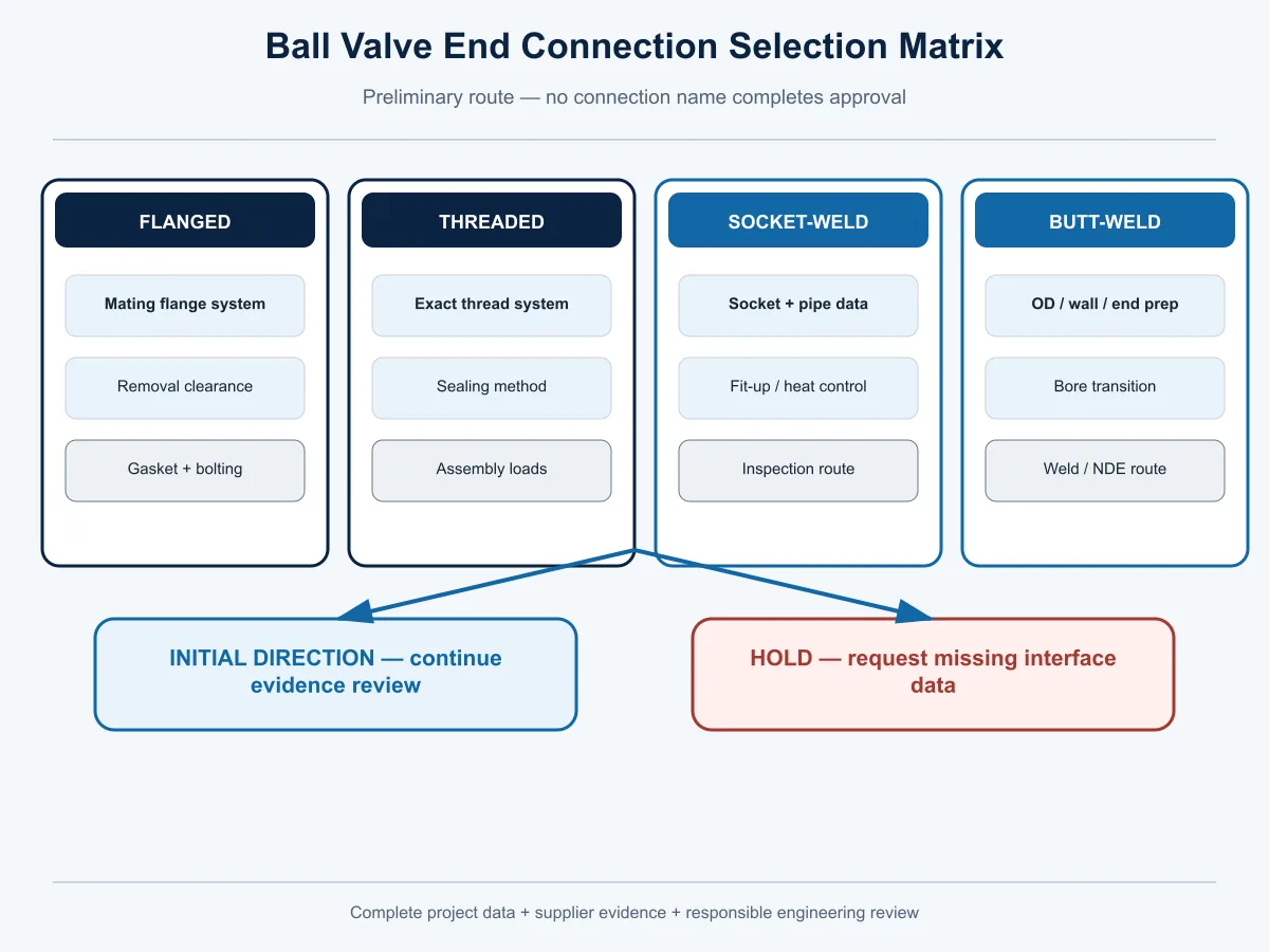
Ball Valve end connection selection matrix with flanged threaded socket-weld butt-weld and Hold conditions
Preliminary selection aid. Final choice requires complete project data, supplier evidence and responsible engineering approval.

Ball Valve End Connection Selection Matrix

Fator de decisão Flangeada Roscada Encaixe para solda Solda de topo Evidence or hold point
Planned removability May support removal without cutting May support disassembly if the layout and thread condition permit Normally requires a controlled cut/rework route Normally requires a controlled cut/re-weld route Confirm isolation, support, access and actual removal path
Space and access Needs flange, bolt and separation clearance Needs assembly/wrenching or rotation access Needs welding and inspection access Needs fit-up, welding and examination access Hold if installation or replacement access is not demonstrated
Mating piping Must match the complete flange system Must match the exact thread and seal system Must match socket and pipe dimensions Must match OD, wall, bevel and internal transition Nominal size is insufficient
External joint elements Gasket and bolting remain controlled parts Thread and seal/sealant remain controlled parts Completed weld and adjacent material are controlled Completed weld and transition are controlled Define supply and approval ownership
Field welding Not inherent at the valve-end joint Not inherent at the valve-end joint Required Required Confirm hot-work, WPS, heat and inspection route
Heat/examination Joint assembly controls apply Thread/seal inspection applies Welding/PWHT/NDE may apply Welding/PWHT/NDE may apply Project procedures remain controlling
Pipe loads/support Misalignment must not be pulled through bolting Assembly torque and pipe strain need control Support during fit-up and welding Support during fit-up and welding Require project stress/support review where applicable
Bore/transition/pigging Check flange bore, valve passage and transitions Check valve passage and fittings Check socket/internal geometry Check end bore and weld transition No piggability conclusion without exact passage evidence
Consequência de vazamento Review gasketed-joint controls Review thread/seal controls Review weld quality and remaining valve leak paths Review weld quality and remaining valve leak paths No connection provides automatic leakage approval
Quotation comparison Normalize flange, gasket/bolting and length Normalize thread/sealing and body arrangement Normalize socket, welding and inspection scope Normalize end prep, welding, NDE and replacement scope Commercial comparison waits for technical normalization
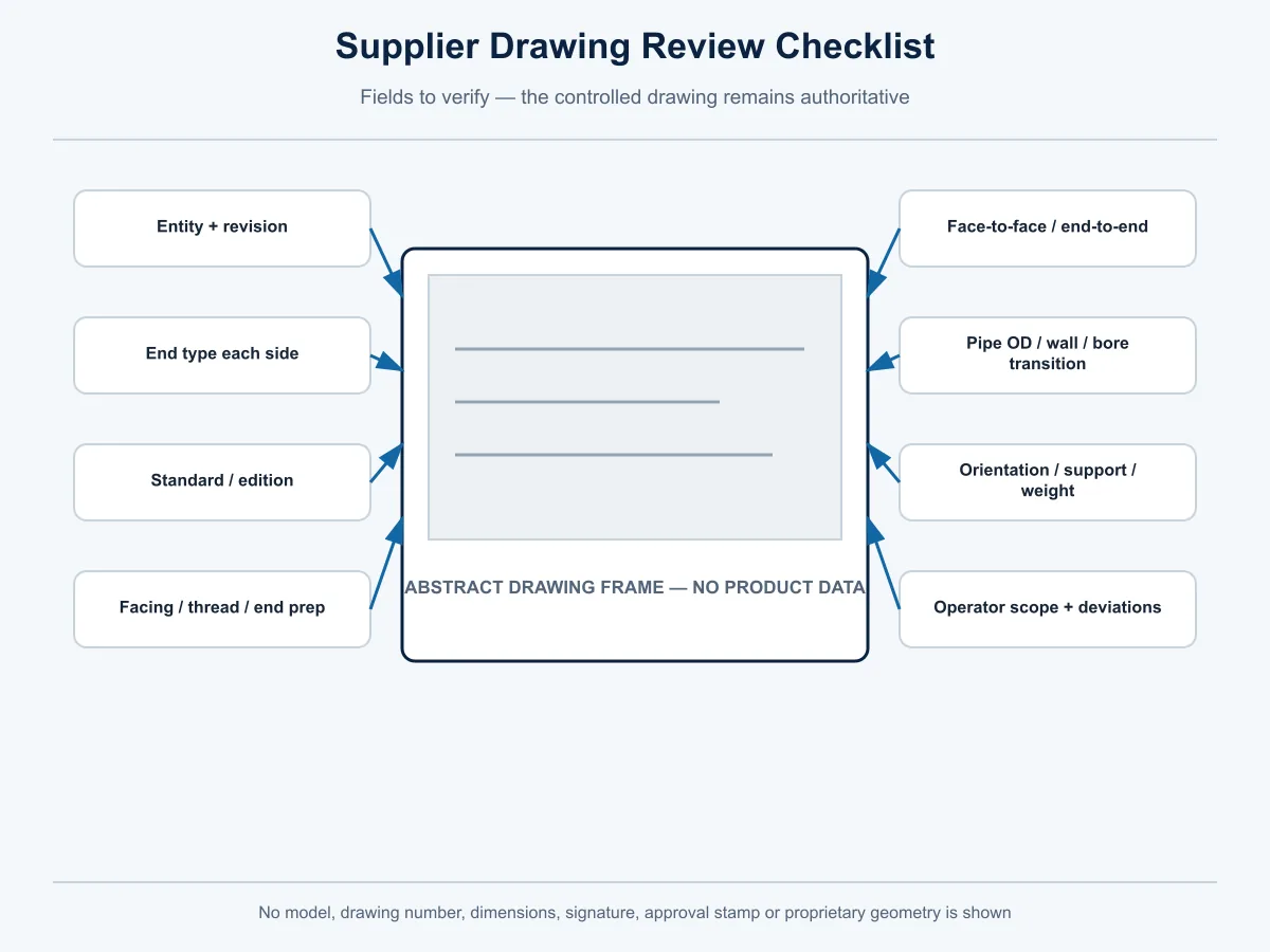
Ball Valve supplier drawing checklist for end details dimensions bore support and operator scope
Evidence checklist only; the exact approved supplier drawing and revision remain controlling.

Review the Supplier Drawing and Evidence, Not Only the Product Name

The approved GA or sectional drawing should identify the exact valve configuration and revision; end type on each side; applicable standard and edition; size and rating; flange, thread, socket or butt-weld detail; face-to-face or end-to-end; pipe/end dimensions and bore transition where relevant; orientation; weight and support points; installation envelope; and operator or actuator scope.

A product photo can show visible configuration. It cannot establish thread form, alloy grade, flange drilling, internal bore, weld preparation, rating, test status or included actuator scope.

Use a supplier evidence matrix before commercial ranking:

Campo Supplier submittal Project requirement Deviation Approval owner Status
Valve/entity and drawing revision Supplier entry Buyer entry Record difference Project/Manufacturer Open/confirmed/deviation
End connection on each side Supplier entry Buyer entry Record difference Piping Engineering Open/confirmed/deviation
Dimensions and mating details Supplier entry Buyer entry Record difference Piping Engineering Open/confirmed/deviation
Materials and joint components Supplier entry Buyer entry Record difference Materials/Project Open/confirmed/deviation
Rating/design basis Supplier entry Buyer entry Record difference Responsible Engineering Open/confirmed/deviation
Installation/welding requirements Supplier entry Buyer entry Record difference Welding/Piping Open/confirmed/deviation
Tests, inspection and documents Supplier entry Buyer entry Record difference Quality/Project Open/confirmed/deviation
Exclusions and alternatives Supplier entry Buyer entry Record difference Buyer approval owner Open/confirmed/deviation

Two quotations are not technically equivalent when one includes the complete mating system and installation evidence while another says only flangeada, roscada ou welded.
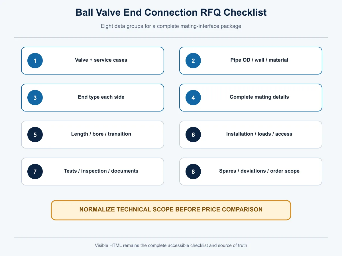
Ball Valve end connection RFQ checklist covering piping interface installation tests documents and deviations
Use the visible RFQ checklist to define the complete mating interface before supplier comparison.

Ball Valve End Connection RFQ Checklist

Include the following in the RFQ, datasheet or technical clarification:

  • valve function, construction requirement if defined, DN/NPS and quantity;
  • medium, full composition, phase, solids and leakage consequence;
  • normal, maximum, design and upset pressure and temperature cases as applicable;
  • pipe OD, schedule/wall, material and corrosion allowance where applicable;
  • pressure class/PN and governing project code/specification;
  • exact end connection on the upstream and downstream sides;
  • flange standard/series/facing/finish/drilling, gasket and bolting; or
  • thread standard/form/designation, orientation and sealing method; or
  • socket dimensions, pipe fit-up and welding/inspection route; or
  • butt-weld end preparation, bore transition and welding/PWHT/NDE route;
  • face-to-face/end-to-end and installation envelope;
  • bore/port requirement, internal transition and pigging or cleaning-device data;
  • piping loads, supports, orientation, lifting and access;
  • body, ball, stem, seat, packing, seal, gasket and bolting requirements;
  • manual, gear or actuated operation; torque basis, fail action, supply and accessories where automated;
  • pressure, seat, functional and any separately required qualification/test scopes;
  • inspection, witness, drawing, IOM and document requirements;
  • spare, removal and replacement strategy;
  • quantity, destination/project and delivery/document milestones; and
  • a visible list of technical deviations, alternatives and exclusions.

Final selection depends on the complete approved datasheet, drawing, project specification and supplier evidence—not only valve size, pressure class or an end-connection name.

Common Specification Errors and Their Corrective Checks

Error Corrective buyer action
Writing only flangeada, roscada ou welded Define the complete mating interface and adopted standard/edition
Treating fully welded body as proof of butt-weld ends Record body construction and pipe-end connection as separate fields
Mixing NPT, BSPT and BSPP terminology Confirm the exact thread form, designation, sealing mechanism and gauges
Combining socket-weld and butt-weld under one procurement line State the exact end on each side and attach the controlled detail
Matching only DN/NPS and Class/PN Verify dimensions, material/rating basis, end system, valve length and service cases
Assuming a flange standard defines valve length Confirm the separate face-to-face/end-to-end basis and approved GA
Assuming welded ends remove all leakage risk Review weld quality plus body joints, stem sealing and every remaining pressure-boundary interface
Assuming flanged or threaded means easy removal Verify isolation, support, access, clearance and reassembly work
Approving from a generic photo Require the exact model drawing, datasheet and revision
Omitting field-work ownership Assign welding, PWHT, NDE, gasket, bolting, sealant, inspection and acceptance responsibilities
Comparing bids with different interface assumptions Normalize all joint elements, installation scope, tests, documents and deviations before price ranking

Resumo da Decisão

Shortlist a flanged end when a verified mating-flange route and planned removability support it. Shortlist a threaded end only when the exact thread and sealing system fit the project rules. Shortlist socket-weld or butt-weld only after the pipe dimensions, welding and examination route, valve construction and replacement plan are reconciled. Treat wafer/flangeless as a special flange-mounted arrangement with its own compatibility checks.

Hold technical approval whenever the interface identity, dimensions, joint components, installation controls, product evidence or supplier deviations remain open.

Request Ball Valve End Connection Review

Send the valve datasheet, piping specification, design cases, pipe dimensions, required end connection, GA or end-detail drawing, materials, actuation requirements, testing/document scope and supplier deviations.

Mark each submitted interface field as CONFIRMED, ASSUMED ou OPEN, and attach the exact supplier offer, drawing revision and technical deviation schedule.

Submit the project data and supplier offer for a preliminary completeness and consistency review. Final piping design, welding acceptance, material approval and project acceptance remain with the responsible project parties.

Explore the current industrial Ball Valve range after the interface and service requirements have been defined.

Perguntas Frequentes

What are the main Ball Valve end connection types?

The four core pipe-end groups used in this guide are flanged, threaded, socket-weld and butt-weld. Specialized flange-mounted or application-specific arrangements should be recorded separately and verified against the exact valve and piping system.

Is a wafer Ball Valve an end connection type?

It is more precise for procurement to treat wafer/flangeless as a special flange-mounted arrangement rather than a pipe-end preparation parallel to a thread or weld bevel. Confirm the exact model, mating flanges, bolting, sealing, centering and installation limits.

What is the difference between socket-weld and butt-weld Ball Valve ends?

A socket-weld joint inserts the mating pipe into a controlled socket before welding. A butt-weld joint joins prepared valve and pipe ends. The two routes require different geometry, fit-up and inspection information and must not be combined as a generic welded RFQ field.

Are flanged Ball Valves easier to remove than welded Ball Valves?

Flanged construction may allow removal without cutting, but only after safe isolation and when the piping is supported and the layout provides bolt and flange-separation clearance. Welded ends normally require a controlled cutting and re-welding plan.

Can NPT, BSPT and BSPP threads be connected interchangeably?

Do not assume so. Confirm the exact thread standard, form, taper or parallel condition, dimensions, sealing mechanism and approved adapter route, if any, before procurement or assembly.

Which Ball Valve end connection is best for high-pressure service?

There is no universal answer from pressure class alone. Review the complete valve rating basis, pipe system, materials, design pressure and temperature, joint requirements, loads, installation, inspection and project specification.

Does a welded Ball Valve eliminate external leakage risk?

No. A welded pipe-end joint removes a detachable gasketed or threaded joint at that location, but weld quality and other pressure-boundary interfaces still require design, installation, inspection and maintenance controls.

What must an RFQ state besides flanged, threaded or welded?

State the exact standard and edition, dimensions, rating basis, facing/thread/end preparation, joint components, pipe data, valve length, bore transition, installation and inspection requirements, replacement strategy and supplier deviations.

Does the flange standard also define the valve face-to-face dimension?

Not automatically. Flange-system requirements and valve face-to-face/end-to-end requirements have different roles. Verify both against the applicable project references and the approved valve drawing.

Can a fully welded Ball Valve have flanged ends?

Potentially, because body construction and pipe-end connection are separate classification axes. Product availability and the exact offered configuration must be confirmed from the controlled model datasheet and drawing.

Nota de Engenharia

Propósito: help engineers and procurement teams distinguish connection labels from complete piping interfaces, identify missing inputs, normalize supplier offers and prepare an auditable RFQ.

Premissas e limites: no exact Raymon Valve model, size range, rating, end availability, material, bore, face-to-face, torque, leakage result, welding route, qualification, test or certificate is approved by this article. Those fields depend on the exact offered configuration, controlled evidence and project requirements.

Confirmação do projeto: final piping design, pressure-temperature review, material selection, welding and examination procedures, support/layout approval, actuator sizing, inspection plan and order acceptance remain with the responsible project and supplier parties.

Editorial owner: Raymon Valve Technical Content Team. This organizational attribution does not claim an individual engineer's license, project authority or order-specific approval.

Reference review scope: official ASME product-page scopes were rechecked on 27 August 2026. The project edition, applicability and exact product evidence still require confirmation.

Deixe um comentário

O seu endereço de e-mail não será publicado. Campos obrigatórios são marcados com *

pt_BRPortuguese
Rolar para cima