
A butterfly valve selection guide should compare three independent design dimensions: disc-and-shaft geometry, body end connection, and seat construction. The main butterfly valve types—concentric, double-offset and triple-offset—describe geometry; wafer, lug and flanged describe connection; resilient, polymer-based and metal describe seat construction. These features can be combined in one valve. The correct combination depends on the process medium, pressure and temperature envelope, differential pressure, leakage requirement, materials, operation and project specification.
Quick Butterfly Valve Selection Snapshot
| Domanda di selezione | Preliminary design route | Critical checks |
|---|---|---|
| Clean water, HVAC, or general utility isolation | Concentric resilient-seated design | Seat compatibility, pressure-temperature rating, shut-off differential pressure, flange alignment |
| Higher cycling duty or reduced seat rubbing | Double-offset / high-performance design | Seat design, torque, cycle conditions, pressure rating and leakage basis |
| Elevated temperature or demanding metal-seat shut-off | Triple-offset metal-seated design for review | Metal-seat leakage criterion, thermal movement, packing, torque and test basis |
| Compact pipeline installation | Wafer connection for review | Mating flange condition, bolting arrangement, disc clearance and pipeline restraint |
| Downstream maintenance or possible end-of-line duty | Lug connection for review | Exact lug design, allowable end-of-line pressure, flange arrangement and bolting |
| Large or structurally demanding pipeline interface | Double-flanged connection for review | Flange drilling, face-to-face dimension, loads, supports and installation space |
This table is a screening aid, not a universal recommendation or a substitute for the approved valve datasheet and project review.
1. Cos'è una valvola a farfalla?
A butterfly valve is a quarter-turn valve that uses a rotating disc to isolate, start, stop, or regulate flow. Its compact construction and relatively short face-to-face dimension can be useful in water, HVAC, utility, chemical, power, and industrial pipeline systems.
A butterfly valve should be treated as a complete assembly: body, disc, shaft, seat, end connection, packing, operator or actuator, and the specified inspection and test basis. Nominal pipe size alone does not define the correct construction. A request such as “DN200 butterfly valve” still leaves the pressure class, medium, temperature, seat, leakage requirement, flange standard, operation and torque basis unresolved.
2. Butterfly Valve Types by Disc and Shaft Geometry
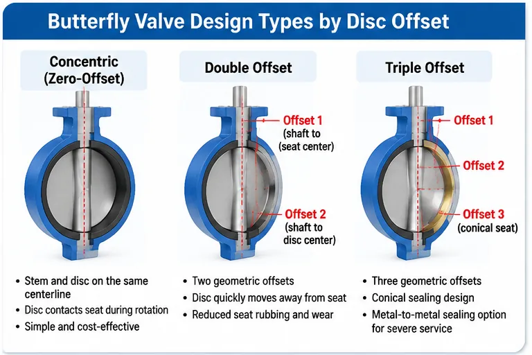
The offset classification describes the relationship between the shaft, disc and seat geometry. It is separate from the body connection and seat-material classifications.
2.1 Concentric (Zero-Offset) Butterfly Valve
In a conventional concentric design, the shaft and disc are arranged around the valve centerline and the disc interacts with the resilient seat during rotation. This construction is commonly considered for water, HVAC, cooling-water and general utility duties when the elastomer and design rating match the service.
- Relatively simple construction and compact installation.
- Resilient seat contact is part of the sealing arrangement.
- Seat compound compatibility, temperature, differential pressure and cycling affect service suitability.
- Frequent throttling, abrasive solids or elevated-temperature duty require additional review.
2.2 Double-Offset (High-Performance) Butterfly Valve
A double-offset design uses two geometric offsets in the shaft, disc and seat arrangement. The geometry is intended to move the disc away from the seat as the valve opens, reducing rubbing compared with a conventional concentric arrangement.
- May be considered where cycling duty or seat-wear concerns justify an offset design.
- Seat construction can be resilient, polymer-based or another model-specific arrangement.
- Pressure capability is determined by the complete design and rating, not by the “double-offset” label alone.
- Torque, shut-off differential pressure and leakage acceptance must be defined.
2.3 Triple-Offset Butterfly Valve
A triple-offset design adds a third geometric offset that produces a conical or inclined sealing arrangement in designs using this principle. The intended effect is to minimize rubbing between the sealing surfaces during travel, with contact concentrated near closure. Many industrial triple-offset designs use metal seating for demanding temperature or shut-off duties.
- Consider for metal-seated isolation where the service data justify the design.
- Review thermal movement, sealing-surface geometry, packing, bearing arrangement and operating torque.
- Specify the required leakage acceptance criterion and test procedure.
- Metal seating does not mean zero leakage; acceptance depends on the specified test basis and valve design.
For the available product-family information, consult the Butterfly Valves product category. Confirm whether a specific triple-offset configuration is available against the current product datasheet and quotation.
3. Butterfly Valve Types by Body End Connection

End connection describes how the valve interfaces with the pipeline. It does not determine whether the valve is concentric, double-offset or triple-offset, and it does not define the seat material.
3.1 Wafer Type
A wafer butterfly valve is installed between two mating pipeline flanges and secured using the specified bolting arrangement. Its compact envelope can be useful where installation space and weight are important. Before ordering, confirm flange compatibility, centering, gasket arrangement, bolt loading, disc clearance and pipeline restraint.
3.2 Lug Type
A lug butterfly valve has threaded lugs around the body. Depending on the actual design, this arrangement can support installation and maintenance configurations where one side of the pipeline may need to be disconnected. Do not assume that every lug valve is suitable for dead-end or end-of-line service. Confirm the manufacturer’s allowable pressure, bolting arrangement, flange configuration and specified end-of-line rating.
3.3 Double-Flanged Type
A double-flanged butterfly valve has integral flanges on both sides of the body. It may be considered for larger pipeline systems or installations where the specified flange interface, structural arrangement and maintenance access favor this construction. Check flange drilling, facing, face-to-face dimension, support loads and removal clearance.
3.4 Butt-Weld End Type
A butt-weld-end butterfly valve is designed to be welded into a compatible pipeline. Review the body and pipe materials, end preparation, qualified welding procedure, heat input controls, installation sequence and inspection access. Welding requirements must be established by the project and responsible welding authority.
| Connessione | Vantaggio potenziale | Checks before purchase |
|---|---|---|
| Wafer | Compact, relatively light arrangement | Flange condition, centering, gasket, bolting and disc clearance |
| Lug | Can offer maintenance flexibility depending on design | Threaded lug details, bolting and end-of-line rating if required |
| Double-flanged | Direct flanged interface and defined body flange arrangement | Flange standard, facing, dimensions, loads and supports |
| Saldatura di testa (Butt-weld) | Welded pipeline interface | Material compatibility, weld procedure, heat input and NDE access |
4. Butterfly Valve Types by Seat Construction

Seat construction is a third independent classification dimension. The seat must be evaluated against the actual medium, concentration, temperature, pressure differential, cycling, shut-off requirement and cleaning or shutdown exposure.
| Seat construction | Typical review direction | Main limitations to assess |
|---|---|---|
| Resilient / elastomeric | Water, HVAC and compatible general utility service | Compound compatibility, temperature, pressure differential, compression and cycling |
| PTFE-based | Selected chemical duties where the specific polymer is compatible | Cold flow, deformation, support design, pressure, temperature and vacuum conditions |
| Sede metallica | Selected elevated-temperature or demanding industrial isolation duties | Leakage criterion, surface finish, hardness, torque, wear and test procedure |
EPDM is often reviewed for water-related services, while NBR may be considered for selected oil-containing media. PTFE-based materials are considered for many chemical duties, but compatibility is concentration- and temperature-dependent. No seat material should be approved from its generic name alone.
5. How the Three Classification Dimensions Work Together
A complete valve description combines the geometry, body connection and seat arrangement. These are not mutually exclusive product types.
| Example configuration | Geometria | Connessione | Seat concept |
|---|---|---|---|
| General utility configuration | Concentric | Wafer or lug | Compatible resilient seat |
| Higher-cycle industrial configuration | Doppio eccentrico | Wafer, lug or flanged as designed | Resilient or polymer-based as designed |
| Demanding temperature isolation configuration | Triplo eccentrico | Flanged or butt-weld as designed | Sede metallica |
| Chemical-service configuration | Concentric or offset, subject to duty | Wafer, lug or flanged as designed | Compatible PTFE-based or other specified seat |
These rows illustrate how a specification can be assembled; they are not blanket recommendations. Confirm each combination against the manufacturer’s design, pressure-temperature rating, materials and project requirements.
6. Butterfly Valve Selection by Application
- Water treatment and municipal systems: Review resilient-seated wafer, lug or flanged designs according to line size, pressure, water chemistry, installation and maintenance requirements.
- HVAC and building utilities: A concentric resilient-seated design may be a starting point where the seat, rating, flange interface and shut-off conditions are suitable.
- Chemical processing: Select body, disc, shaft, seat, liner, packing and gasket materials from the complete chemical composition, concentration, temperature and cleaning conditions.
- Steam and elevated-temperature service: Review metal-seated and offset designs where required, including thermal movement, packing, leakage criteria and actuator torque.
- Abrasive or solids-bearing media: Evaluate disc-edge exposure, erosion, seat damage, plugging, velocity and whether a butterfly valve is appropriate for the duty at all.
7. Materials, Pressure and Temperature Review
Body material alone does not establish valve compatibility. Review the pressure boundary, disc, shaft, seat, packing, gasket, fasteners, coating or lining as a component-level material system.
- Identify the medium, phase, composition, concentration and contaminants.
- Record normal, minimum, maximum and design pressure and temperature.
- Establish differential pressure at opening and closure, including credible transients.
- Check corrosion, erosion, solids, fouling, external environment and cleaning exposure.
- Confirm the pressure-temperature rating for the exact body, trim and seat construction.
Published material compatibility charts and nominal temperature ranges are screening references only. Final suitability requires the actual grade, compound, construction and project conditions.
8. Actuation and Operating Torque
Butterfly valve operation may be manual by lever or gearbox, or automated using pneumatic, electric or hydraulic actuation. The operator should be selected from the valve manufacturer’s torque data and the project operating cases—not from nominal size alone.
- Required breakaway, running and seating torque across the operating envelope.
- Maximum differential pressure and direction of pressure loading.
- Seat type, material, temperature and cycle history.
- Operating time, frequency and control mode (on/off or modulating).
- Available air or electrical supply, accessories and environmental conditions.
- Required fail position, manual override and control interfaces.
Final actuator sizing requires the exact valve torque data, service conditions, utility supply and specified margin. This guide does not provide a universal actuator size.
9. Standards, Testing and Documentation
Specify the governing documents by scope and controlled edition. Depending on the product and project, the review may include a butterfly valve product/design standard, face-to-face and flange dimensional standards, pressure and leakage test requirements, material specifications, coating requirements and actuator specifications.
API 609 and ISO 10631 are relevant references for certain industrial butterfly valve scopes, but their scopes and product configurations are not interchangeable by assumption. ISO 10631:2021 specifies general requirements for metallic-bodied butterfly valves used in flanged or butt-welding piping systems, including design, materials, pressure/temperature ratings and testing. The official ISO catalogue records the 2021 edition as reviewed and confirmed in September 2026, so it remains current. API’s official standards catalogue lists a May 2026 update for the tenth edition of API 609. Confirm the controlled edition, contractual applicability, effective date and purchaser options against the project specification and current API publication before placing an order.
Neither standard reference proves that a particular Raymon Valve model is compliant or certified. Request the applicable declaration, product datasheet, drawings and inspection/test records for the exact offered construction. Do not state API 609 conformity solely because a valve is wafer, lug or double-flanged; confirm that the exact valve type, size, class, materials and construction fall within the specified edition and purchase scope.
For a broader reference list, review valve standards and dimensional requirements. For testing scope and evidence planning, consult the Valve Pressure Testing resource. Shell, closure, functional, fire-safe and fugitive-emission tests address different requirements and should not be treated as interchangeable. See the official ISO 10631:2021 catalogue entry e API’s official standards catalogue for edition checks.
10. Butterfly Valve Selection Decision Matrix

Use the matrix to identify candidate configurations, then close the open technical points in the datasheet review. A single service label such as “steam,” “chemical,” or “water” is not enough to finalize a valve selection.
| Service or installation condition | Configuration to evaluate | Decision checks before specification | Non dare per scontato |
|---|---|---|---|
| General water or HVAC isolation | Concentric, resilient-seated; wafer, lug or flanged connection as required | Water chemistry, seat compound, design pressure and temperature, differential pressure, flange interface and shut-off requirement | That every elastomer or concentric design has the same rating or leakage capability |
| Higher cycling or reduced seat rubbing is important | Double-offset design with model-specific seat construction | Cycle frequency, pressure differential, torque profile, seat wear mechanism and required leakage acceptance | That the double-offset label establishes pressure class, cycle life or shut-off performance |
| Elevated temperature or metal-seat isolation | Triple-offset metal-seated design for engineering review | Temperature range and transients, sealing geometry, material pairing, packing, torque and specified test procedure | That metal seating means zero leakage or automatic suitability for steam |
| Compact installation between pipeline flanges | Connessione wafer | Flange drilling and facing, gasket position, centering, bolting, disc sweep clearance and pipeline restraint | That wafer construction is suitable for every flange arrangement or end-of-line duty |
| One-side pipeline disconnection may be required | Lug connection, subject to exact design | Threaded lug details, bolt engagement, allowable end-of-line pressure, flange arrangement and manufacturer instructions | That every lug valve is rated for dead-end service |
| Large line or defined flanged interface | Double-flanged connection | Flange standard, pressure class, face-to-face dimension, structural loads, supports and maintenance clearance | That flange compatibility alone confirms the valve pressure-temperature rating |
| Chemical or solids-bearing medium | Geometry and connection selected only after component-level material review | Full composition and concentration, temperature, solids, corrosion/erosion mechanism, seat, shaft, packing and gasket compatibility | That body material or a generic polymer compatibility chart approves the complete valve |
The matrix is a preliminary screening tool. Confirm the exact model, construction, pressure-temperature rating, leakage basis and installation limits in the approved datasheet and project specification.
11. Failure Modes, Possible Causes and Verification
Use this matrix during technical bid review, commissioning planning or troubleshooting. The listed causes are possibilities to investigate, not diagnoses. Confirm the actual failure mechanism through inspection, operating records and the approved valve design.
| Observed symptom | Possibili cause | Verification / evidence to request |
|---|---|---|
| Seat leakage or failure to isolate | Incorrect seat material, damaged sealing surfaces, debris, installation misalignment, unsuitable differential pressure or incorrect closure setting | Review medium and temperature history, leakage test basis, seat inspection, disc condition, installation records and actuator travel/stop settings |
| Abnormally high operating torque | Pressure differential, seat compression, deposits, corrosion, shaft/bearing condition, misalignment or incorrect actuator setup | Compare measured torque/current or air-supply behavior with the manufacturer’s torque data; inspect bearings, shaft, seat and pipeline alignment |
| Stem / shaft packing leakage | Packing wear, chemical or temperature incompatibility, shaft surface damage, installation issue or pressure outside the specified envelope | Review packing specification, process conditions, maintenance history, shaft finish and the applicable fugitive-emission or leakage test requirement |
| Disc interference or incomplete travel | Insufficient pipe clearance, flange/gasket intrusion, deposits, incorrect installation orientation or mechanical stop setting | Check approved dimensional drawing, actual pipe internal diameter, gasket position, disc sweep clearance and travel-stop setup |
| Accelerated seat or disc wear | Frequent cycling, throttling outside the approved range, abrasive solids, cavitation/erosion conditions or unsuitable material pairing | Review operating profile, flow conditions, medium solids, inspection photographs, material specification and manufacturer application limits |
| External corrosion or coating damage | Unsuitable external environment, coating damage, incompatible material selection, poor storage or installation exposure | Check coating specification, environmental exposure, material certificates where specified, preservation records and inspection findings |
Confine ingegneristico: Do not increase actuator size or change seat material solely from a symptom description. Confirm the valve model, process conditions, manufacturer torque data and failure evidence first.
12. Supplier Evidence and Technical Bid Review
Ask each bidder to identify which documents are included, which are available on request, and which are excluded. The required document list should follow the purchase specification, inspection and test plan (ITP), jurisdiction and project quality requirements. For additional background on production stages, see the processo di produzione valvole; use project-specific records, rather than a general process description, to verify the supplied valve.
| Evidence / document | What the buyer should verify | When it is relevant |
|---|---|---|
| Product datasheet and GA drawing | Exact model, size, rating, materials, face-to-face, flange/end details, flow direction or installation limits, weight and operator interface | Every technical bid |
| Material test certificates (MTCs) | Heat/lot traceability, grade, specification, required testing and consistency with the approved material list | When specified by code, PO or project ITP |
| Pressure and closure test records | Test procedure, medium, pressure, duration, acceptance criteria, test direction, instrument status and valve identification | When required by the governing standard or purchase specification |
| Piano di ispezione e collaudo (ITP) | Hold/witness/review points, inspection stages, acceptance documents and responsible parties | Project quality control or third-party inspection scope |
| Actuator sizing / torque data | Valve torque basis, differential pressure cases, safety factor basis, supply conditions, fail action and accessory compatibility | Valvole attuate |
| Welding and NDE records | Applicable WPS/PQR/WPQ, weld map, NDE method, acceptance criteria and traceability | Butt-weld ends or welded construction when specified |
| Special-service qualification | Exact test scope, model/size/material coverage, acceptance criteria and certificate/report validity | Only where fire-safe, fugitive-emission, cryogenic, sour-service or other qualification is specified |
| Registro di produzione finale | Index, approved deviations, inspection records, certificates, test reports, marking and release documents | When required by the contract or project |
This is a buyer-side evidence request list. It does not state that every document or qualification is automatically included in Raymon Valve’s standard supply scope. Confirm availability and commercial inclusion in the quotation.
13. Installation and Commissioning Risk Checks
- Confirm the valve face-to-face dimension, flange drilling, facing and pressure class against the piping specification.
- Check disc sweep clearance against the actual pipe internal diameter, lining, gasket and adjacent components.
- Verify flow direction, shaft orientation and actuator clearance against the manufacturer’s installation instructions.
- Prevent piping misalignment or external loads from being transferred into the valve body beyond its design allowance.
- Confirm the lug or wafer bolting sequence and tightening method specified for the valve design.
- For butt-weld ends, agree the welding sequence, heat-input controls, protection of soft components and inspection access before installation.
- Before commissioning, verify travel stops, position indication, actuator utilities, fail action and safe functional test procedure.
14. Butterfly Valve RFQ Checklist
- Valve tag, quantity and required function (isolation, throttling or other duty).
- Medium composition, phase, concentration, solids and contaminants.
- Normal, minimum, maximum and design pressure and temperature.
- Differential pressure, flow cases and operating frequency.
- Nominal size, pressure class or PN, and required pressure-temperature rating.
- Geometry: concentric, double offset or triple offset, if specified.
- Body connection: wafer, lug, double-flanged or butt-weld.
- Flange standard, facing, drilling, face-to-face dimension and disc clearance.
- Body, disc, shaft, seat, packing, gasket, fastener and coating/lining materials.
- Shut-off requirement, leakage acceptance and test direction.
- Manual or actuated operation, torque basis, fail position and accessories.
- Inspection, testing, material certificates, NDE/PMI and third-party witness requirements.
- Installation orientation, pipeline loads, access and maintenance clearance.
- Required drawings, datasheets, IOM manuals and final manufacturing records.
15. Frequently Asked Questions
What are the main types of butterfly valves?
They can be classified by disc and shaft geometry (concentric, double offset and triple offset), body connection (wafer, lug, double-flanged and butt-weld), and seat construction (resilient, PTFE-based and metal). These dimensions can be combined in one valve configuration.What is the difference between concentric and double-offset butterfly valves?
A concentric design uses a centerline arrangement with resilient seat contact during rotation. A double-offset design uses two geometric offsets intended to move the disc away from the seat during opening and reduce rubbing. Actual pressure, leakage and cycle capability depend on the complete design.When should a triple-offset butterfly valve be considered?
It may be considered when a project requires a metal-seated arrangement or has demanding temperature and shut-off conditions. Confirm the exact leakage criterion, materials, torque, thermal conditions and test basis.What is the difference between wafer and lug butterfly valves?
A wafer valve is installed between mating flanges. A lug valve has threaded lugs and may provide different bolting and maintenance arrangements. Dead-end suitability must be confirmed against the exact design rating and installation conditions.Are metal-seated butterfly valves suitable for steam?
Some metal-seated designs are considered for steam service, but suitability depends on pressure, temperature, steam condition, materials, packing, leakage requirement, torque and the manufacturer’s rated construction.How do I select a butterfly valve seat material?
Start with the full medium composition and concentration, operating and design temperatures, pressure differential, cycling, shut-off requirement and cleaning exposure. Confirm the exact compound or polymer grade with the manufacturer.Can a lug butterfly valve always be used for dead-end service?
No. Lug construction alone does not establish end-of-line capability. Check the manufacturer’s allowable pressure, valve design, flange arrangement, bolting and project installation basis.What information is needed for a butterfly valve quotation?
Provide the valve function, medium, pressure and temperature cases, size, pressure class, connection and flange standard, materials, seat, leakage requirement, actuation, tests, documents and quantity.
Conclusione
Butterfly valve types should be compared across three separate dimensions: disc and shaft geometry, body end connection, and seat construction. The correct combination depends on the real process envelope, material compatibility, shut-off requirement, installation arrangement, operating torque and evidence required by the project.
Use this guide to prepare a technically complete shortlist and RFQ. For broader application discussions, review Soluzioni per valvole industriali. Final suitability must be confirmed against the approved datasheet, applicable standards and editions, manufacturer drawings, pressure-temperature rating and project requirements.
Request a Butterfly Valve Selection Review
Send the valve function, medium and composition, normal and design pressure and temperature, size, pressure class, end connection, material and seat requirements, leakage criterion, actuation method and required tests. Include the project datasheet or specification where available.
Raymon Valve can review the supplied information and identify the technical points that require confirmation. Final product suitability and order scope remain subject to approved project documents.
Related Raymon Valve Resources
- Butterfly valve product range – review the product-family configurations.
- Valve pressure testing – review testing scope and evidence requirements.
- Chi siamo – company information.
Technical assumptions and limits: This resource supports preliminary engineering screening and RFQ preparation. It assumes that the reader will establish the actual medium composition, phase, operating/design pressure and temperature, differential pressure, leakage requirement, installation arrangement and governing project documents. It is not a project-specific calculation, material approval, certification or guarantee of fitness for service. The accepted purchase order, approved datasheet, drawings, specifications, controlled standards editions and documented deviations govern the supplied scope. No individual technical author or independent engineering reviewer has been identified for this draft. Add a named, accountable reviewer only after the page has received the relevant engineering review.
 Italian
 English
 German
 Arabic
 French
 Spanish
 Portuguese
 Russian