
Check Valves · Engineering Selection
Check valve cracking pressure is the forward differential pressure at which the closure member first begins to open and detectable flow starts under specified test conditions. It does not establish full opening, stable minimum flow, or operating pressure loss. Spring preload, effective pressure area, mounting direction, friction and downstream backpressure may alter the opening requirement. For pump startup, compare the available pressure difference at the valve with the accepted cracking-pressure limit, then verify steady-flow behavior and reverse sealing as separate engineering checks.

- Define the governing window: Identify when forward flow must start. Record valve-side P1 and P2 during that interval, including header pressure, pump speed or start sequence and uncertainty.
- Specify an accepted opening limit: Obtain the quoted valve and spring/trim configuration, nominal setting, upper acceptance threshold, tolerance and matching first-flow test conditions.
- Screen and disposition: Compare the lowest credible available differential with the accepted upper threshold. A nonpositive margin means opening is not demonstrated; a positive static screen still requires operating-flow and time-dependent checks. Mark missing or incompatible evidence as HOLD.
What Is Check Valve Cracking Pressure?
Cracking pressure is the initial opening threshold of a check valve. In a normally closed spring-loaded construction, fluid pressure must overcome the net forces holding the closure member against its seat. Manufacturers may report the result in psi, bar, or kPa, but the number must be read together with its test method.
For engineering procurement, ask whether the quoted value is a nominal spring setting, a minimum-to-maximum accepted range, or a verified maximum initial opening threshold. Confirm the exact model, spring option, fluid, test temperature, installation orientation, and first-flow detection criterion.
Cracking Pressure vs Opening Pressure
The terms are sometimes used interchangeably, but opening pressure may also describe the pressure required to reach a specified opening position. A supplier should state whether its figure relates to first detectable flow or to another defined condition. Do not assume that two manufacturers use identical terminology.
Cracking Pressure vs Fully Open Pressure Drop
At initial cracking, a small flow passage exists; the valve may still have substantial resistance. Its subsequent opening position is governed by fluid forces and the exact construction, which must be evaluated using operating data rather than the cracking specification.
Cracking Pressure vs Resealing Pressure
Resealing pressure describes the condition at which the valve returns to its specified closed or leakage-limited state after forward flow decreases. It is not automatically equal to cracking pressure. Spring closing force, reverse differential pressure, friction, seat design, and contamination may affect resealing. Initial opening performance is not proof of reverse leakage performance or positive isolation.
How Does Spring Force Affect Check Valve Cracking Pressure?
Spring-loaded check valves use a mechanical spring to apply a closing load to a disc or poppet. The spring helps establish the initial opening threshold and may influence closing response. Its behavior must be assessed together with geometry, effective pressure area, gravity, mechanical resistance, and fluid forces.

Spring Preload and Initial Opening Force
Spring preload is the closing force already present when the closure member is seated. For a highly simplified static, axial arrangement, forward pressure force can be expressed conceptually as:
The relation helps explain why the initial spring force and effective pressure area matter. It is not a universal check-valve cracking-pressure calculation. Real valves may have multiple wetted areas, seat-contact effects, friction, nonuniform pressure fields, and changing hydrodynamic loads. Hinged discs require a moment balance rather than only an axial-force balance.
Spring Stiffness, Disc Travel, and Opening Position
Preload describes the spring force at its initial installed position; spring stiffness describes how that force changes with travel. In an ideal linear compression spring:
Here F0 is the seated preload, k is the spring rate, and x is additional compression. As the member moves, the spring and flow forces change together. First opening therefore does not establish the flow required for a larger or stable opening.
Gravity, Orientation, Friction, and Seat Adhesion
Gravity may assist or oppose motion depending on the internal construction and permitted installation direction. Application example: in a vertical downward-flow installation, a guided poppet’s weight may assist opening and oppose spring-assisted closure; in upward flow, the same weight may increase the force needed to begin opening. This effect is configuration-dependent and is not a universal correction in bar or psi. Guides, seals, fouling, wear and inactivity can also change breakaway behavior. Request the manufacturer’s permitted mounting orientation and the corresponding spring/cracking-pressure data rather than transferring a horizontal test value without justification.
What Is the Minimum Differential Pressure Required to Open a Check Valve?
The relevant quantity is the forward differential across the valve, not the upstream gauge pressure alone:
Both values must be measured or calculated at appropriate valve locations on a consistent pressure basis. A positive upstream pressure does not guarantee opening if the downstream system is already pressurized.
Upstream Pressure vs Downstream Backpressure
Consider a hypothetical static startup screen: the pressure immediately upstream of the valve is 3.00 bar, downstream header pressure is 2.85 bar, and the available forward differential is 0.15 bar. Suppose a supplier permits cracking as high as 0.20 bar for the proposed model and defined test conditions. Opening cannot be guaranteed from these data: the actual unit might crack below 0.15 bar, but the accepted upper limit allows a higher threshold. Do not report certain failure or certain opening without an agreed actual threshold and relevant pressure history. The figures are illustrations, not Raymon Valve tests or recommended spring settings.
How to Screen the Startup Opening Margin
For the same defined fluid, orientation, temperature and first-flow test criterion, a preliminary static comparison can be organized as follows:
Apply the startup gate above using valve-side pressures during the period when opening is required. A negative screening margin does not demonstrate the opening requirement; it does not mean that every manufactured unit necessarily remains closed. A positive margin can support only a static first-opening screen, not a guaranteed dynamic start, fully open position or stable operating point. Agree how instrument accuracy, spring tolerance, temperature, medium and transient pressure variation are addressed; do not invent a universal margin or safety factor.
Cracking Differential vs Operating Differential
Initial cracking and established flow are different approval cases. The supplier’s running pressure-loss and opening data must match the offered valve and system flow range. Do not use a static first-flow differential as a substitute for the flowing ΔP–Q characteristic.
Why Low Differential Pressure May Leave a Valve Partly Open
Near the initial-opening threshold, some constructions may remain partly open or respond to fluctuations. This observation alone does not diagnose chatter: use model-specific minimum-flow and opening data, as discussed in the linked sizing resource.
How Does Cracking Pressure Affect System Startup?
Startup conditions can differ significantly from steady operation. The valve may need to open against an existing downstream system pressure before normal flow becomes established.

Pump Startup Against Existing Downstream Pressure
Startup example — pump against a live header: a standby centrifugal pump starts while another unit maintains common-header pressure. The pump discharge pressure increases with speed, but the check valve initially sees an opposing downstream pressure, so a nominal spring setting alone cannot show when the valve first passes flow. Review the pump start sequence and record or calculate valve-side P1 and P2 over the required opening interval. A discharge gauge or design head taken in isolation is not an acceptable substitute for that differential-pressure history.
For the controlling startup case, record whether the header is empty, pre-pressurized or maintained by another running pump; identify valve elevation, fluid state, pump speed or start sequence, and the relevant upstream/downstream pressure history. A single pressure snapshot may miss the moment when the differential is smallest or changing rapidly.
Minimum-flow bypass operation, permitted pump operating region, suction conditions, speed ramp, and transient effects may govern the result. Changing the spring cannot be approved from one isolated cracking-pressure comparison. Where a pressure transient can create a significant consequence, the system engineer must define an appropriate transient assessment in addition to the static opening check.
Static Head and Vertical Installation
In liquid services, pipeline elevations and liquid columns affect pressures available at the valve. If pressure values at the valve already include static head, do not add the same elevation effect a second time. Separately, check whether gravity alters the closure-member force balance in the proposed mounting direction.
Parallel Pumps and Common Header Backpressure
Parallel-pump verification: when the common header is pressurized by operating units, a standby pump may have sufficient steady-state head but insufficient forward differential during part of its speed ramp. Compare one-pump, two-pump, startup, shutdown and trip cases. Request the header-pressure trend, pump curve or validated hydraulic model, valve-side pressure profile and exact-valve opening data. Opening approval must not replace the review of reverse-flow prevention and shutdown transients.
Intermittent Flow and Low-Pressure Systems
Intermittent services may repeatedly operate near the initial opening threshold. Low-driving-pressure applications can make spring tolerance and orientation especially important. Nevertheless, choosing the lowest available spring setting is not universally preferable: closure, resealing, stable opening, and system loss must also be reviewed.
Cracking Pressure vs Pressure Drop: Why the Difference Matters
Cracking pressure describes the onset of detectable forward flow. Operating pressure drop is the pressure difference across the valve at a stated flow rate and operating opening. A partially open valve may have much higher resistance than expected from a fully open flow coefficient.

Initial Opening Does Not Mean Full Opening
Do not apply a manufacturer’s cracking-to-full-opening multiplier to a different valve design. Such relationships are valid only for the stated construction and test basis.
Why Manufacturer Pressure-Drop Curves Matter
Request operating ΔP–Q or opening data for the offered model, spring, medium and orientation, and clarify whether the quoted Cv/Kv assumes fully open geometry. Detailed flow-range sizing belongs to the separate sizing guide.
For an example of why manufacturer-specific evidence matters, la Check-All Valve Application Guidelines describe fully-open behavior relative to the cracking setting for certain Check-All products. Those relationships belong to the stated product series; they cannot be transferred as a universal multiplier to swing, dual-plate, axial-flow, or another supplier’s spring-loaded designs. For a fuller discussion of minimum flow and stable opening, see the check valve sizing and flow-stability guide.
How to Select Cracking Pressure for Different System Conditions
There is no universally correct cracking-pressure setting. An appropriate initial opening threshold must be assessed together with the normal flow envelope, reverse-flow consequences, installation, operating losses, and the supplier’s model-specific evidence.
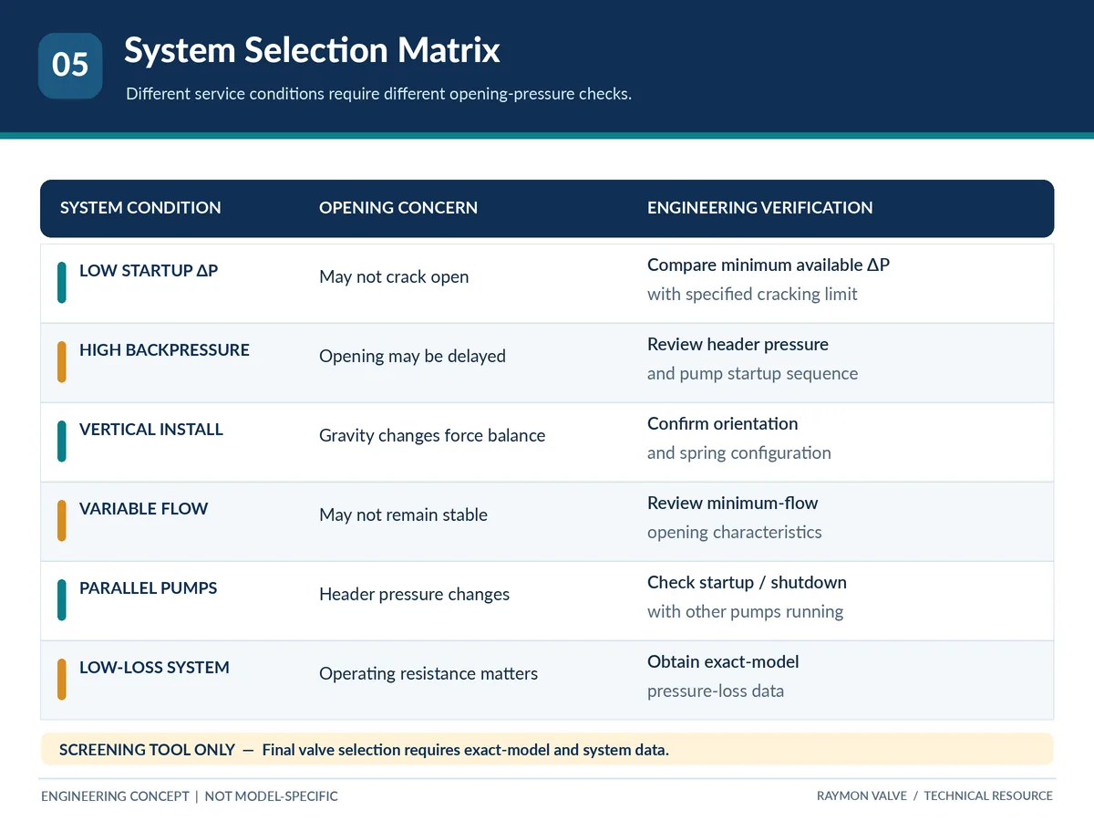
| System condition | Main concern | What to verify |
|---|---|---|
| Low startup differential | Valve may not crack open | Minimum available ΔP versus maximum specified cracking requirement |
| High downstream backpressure | Opening may be delayed | Header pressure and pump startup pressure development |
| Installazione verticale | Gravity may change effective force balance | Approved mounting direction and spring/trim option |
| Low or varying flow | Unstable or insufficient opening | Minimum stable-flow and opening-position data |
| Parallel pump discharge | Header pressure changes by operating case | Startup, running, shutdown, and standby scenarios |
| Limited pressure-loss allowance | Excessive operating resistance | Exact-model ΔP–flow curve with the selected spring |
| Intermittent service | Frequent cycling or breakaway behavior | Opening, resealing, orientation, and repeatability evidence |
Illustrative screening framework only; not an approved model selection or system calculation.
The Selection Trade-Off
A higher opening requirement can be relevant to specific closing objectives but can also demand more differential pressure during startup. A lower threshold can help some low-driving-pressure duties yet does not establish reverse tightness or stable flow. Do not rank candidate valves solely by nominal cracking pressure.
When Can Cracking Pressure Create Operating Problems?
A mismatch between operating conditions and the actual opening characteristic can contribute to poor performance. Symptoms are investigative clues, not proof of a particular root cause.
| Observed symptom | Possible contributor | Evidenza richiesta |
|---|---|---|
| No apparent opening during startup | Insufficient ΔP, obstruction, or internal resistance | Synchronized P1/P2 and startup data; valve condition |
| Flow with incomplete opening | Minimum flow below required operating range | Operating-flow record and exact-model opening data |
| Clicking or flutter | Varying hydraulic forces, pulsation, friction, or wear | Flow, pressure, vibration, and inspection evidence |
| Reverse leakage | Seat condition, deposits, incorrect resealing conditions | Applicable reverse-pressure and seat leakage test |
| Changed behavior after downtime | Deposits or breakaway resistance | Operating history and inspection after safe isolation |
Failure to Open and Insufficient Opening
Start by verifying the actual differential at the valve and the model’s specified cracking range. Then assess whether flow can establish the desired operating position. A single pump discharge gauge, a catalog setting, or a pressure class is insufficient for the diagnosis.
Chatter Near the Opening Threshold
Fluctuating fluid forces can sometimes cause repeated closure-member movement, but disturbed flow, pulsation, wear, or incorrect installation may also be involved. For the separate root-cause workflow, see check valve chatter and slamming diagnosis.
Incomplete Resealing and Reverse Leakage
Cracking pressure alone does not establish reverse leakage. Seat design, reverse pressure, deposits, wear, and closure behavior matter. A check valve should not be assumed to replace a required positive isolation or independent protective device.
How Should Cracking Pressure Be Tested and Verified?
A cracking-pressure test should establish the criterion for first detectable flow under controlled conditions. The supplier should specify the pressure measurement arrangement, test medium, orientation, temperature, acceptance range, and test record requirements.
What the Test Actually Measures
Specify and record four separate fields: (1) nominal spring setting or target (a reference, not necessarily a guarantee); (2) agreed acceptance band including the maximum permitted cracking differential and any minimum limit; (3) the test method defining first detectable flow, instrument setup and measurement conditions; and (4) the documented result or supplier evidence for the exact offered configuration. Do not infer an accepted maximum from the nominal value alone.
Test Medium, Orientation, Temperature, and Repeatability
Air, gas, and liquid tests may differ in their methods and sensitivity. Operating fluid properties, mounting direction, and temperature can influence applicability. Where repeated cycling matters, specify the acceptance procedure and repeatability criteria rather than assuming a generic spring setting proves them.
Agree on measurement locations, instrument range and calibration status, pressure-ramp method, first-flow detection threshold, number of repetitions, allowed variation and record format before the test. Where the production unit cannot be tested under the exact process fluid and temperature, the supplier should state how the proposed test relates to the actual service and identify any unresolved difference. The project specification decides whether supplementary qualification evidence is necessary.
Cracking Pressure Test vs Seat Leakage Test
Opening performance, closure leakage, and shell integrity are separate verification topics. ISO 5208:2015 addresses pressure testing of metallic industrial valves, including pressure-boundary integrity and closure tightness; it does not constitute a universal cracking-pressure performance test. API’s official updates list API 594, 10th edition, and Errata 1 dated October 2026; the standard’s applicability depends on valve construction and the contract’s adopted edition. Neither standard proves a particular startup opening characteristic without model-specific evidence.
What Each Verification Actually Demonstrates
| Evidence or verification | Cosa può supportare | What it cannot establish alone |
|---|---|---|
| Agreed cracking-pressure functional test | First-flow threshold under the documented test conditions and acceptance criteria | Full opening, minimum stable flow, all startup transients, or reverse seat tightness |
| Exact-model pressure-loss / opening data | Operating resistance and opening behavior for the stated size, spring, fluid and conditions | Unmeasured off-curve conditions or a guaranteed closing transient response |
| Seat / closure leakage test | Specified closure tightness at the agreed direction, pressure and acceptance basis | Initial opening threshold or stable operation at low forward flow |
| Shell / pressure-boundary test | Pressure boundary integrity to the applicable test basis | Cracking pressure, flow capacity, spring suitability or system startup performance |
| Project-specific startup / transient evaluation | System-level adequacy for the modeled operating cases and accepted assumptions | Manufactured-unit test results, material traceability or a future guarantee outside the modeled cases |
Acceptance depends on the purchase specification, exact valve construction, applicable standard edition and approved test plan; the table does not assert that each test is mandatory for every project.
Engineering Selection Matrix and RFQ Checklist
A useful RFQ lets the supplier evaluate the initial opening threshold against the controlling operating cases and supply documented evidence for the offered configuration.

| RFQ field | Buyer to provide | Supplier to confirm |
|---|---|---|
| Identificazione valvola | Type, size, class/PN, end connection | Exact model and drawing |
| Servizio | Fluid, phase, temperature, solids, viscosity where relevant | Material and seat suitability basis |
| Flow envelope | Minimum, normal, maximum, intermittent | Operating loss and stable-opening evidence |
| Startup and header | P1/P2 time history at the valve, header initially empty or pressurized, pump start sequence and elevation | Controlling opening condition and any required dynamic review |
| Nominal spring setting | Target or preferred opening setting, if any; identify it as nominal | Exact spring/trim option, reference setpoint and part/configuration identification |
| Accepted cracking band and upper limit | Maximum permitted initial-opening ΔP and any minimum bound under agreed service/test conditions | Explicit accepted range, guaranteed/accepted upper threshold, tolerance and applicable orientation |
| Cracking test method | Test fluid, temperature, orientation, pressure-ramp approach, first-flow detection criterion and repeats | Agreed procedure, measurement locations, instrument/calibration basis, result and record format |
| Operating pressure loss | Allowable ΔP at minimum, normal and maximum flow | Exact-model ΔP–Q data and stable-opening basis for offered spring |
| Installazione | Horizontal/vertical direction, flow arrow, nearby layout, maintenance envelope | Approved orientation and spring/trim configuration |
| Resealing | Reverse differential cases and allowable leakage | Applicable resealing and seat-tightness evidence |
| Documentazione | Product standard and edition, inspection hold points, test/record scope | Drawing, test/inspection document list, explicit exclusions and technical deviations |
Questions Before Technical Bid Approval
- Is the quoted cracking pressure nominal, a guaranteed maximum, or a tested acceptance range under defined conditions?
- Does the accepted upper opening threshold fit the governing available startup differential after considering uncertainty?
- Are minimum-flow and pressure-drop data valid for the offered spring, trim, orientation, size and medium?
- Does the proposal distinguish initial cracking, steady operation, resealing and reverse leakage?
- Are opening, resealing, seat leakage, and shell testing separately identified, with conditions and deliverables?
- Are missing inputs and supplier deviations assigned for closure before order approval?
Technical Bid Approval Gates
Use the following project-screening gates to normalize quotations. A hold is an unresolved engineering question, not proof that a valve will fail. These gates do not replace the responsible engineer’s final design approval.
| Approval gate | Acceptable screening evidence | Hold or reject trigger |
|---|---|---|
| Gate 1 — First opening | Governing startup P1/P2 time window, accepted cracking band/upper limit, tolerance and compatible test basis; uncertainty reviewed | Missing/unmeasured maximum threshold, incomplete pressure history, nominal-only spring setting or unmatched test conditions |
| Gate 2 — Operating duty | Exact-model flow/loss information supporting minimum through maximum flow and permitted installation orientation | No evidence of stable opening or acceptable ΔP for the offered configuration |
| Gate 3 — Closure and records | Agreed reverse leakage / closing requirements, testing basis, drawings, deviations and document deliverables | Opening test incorrectly used as seat-tightness proof, or unresolved specification exceptions |
Record status for each valve tag as demonstrated, hold for evidence, or not acceptable to the specification. Do not convert unknowns into assumed compliance.
Final Check Valve Cracking Pressure Selection Recommendations
1. Can the Valve Open During Startup?
Document the outcome of the three-step gate: governing startup pressure window, accepted maximum threshold, and margin with uncertainties. A static pass is a review input; time-dependent startup suitability remains a separate decision.
2. Can the Valve Operate Reliably Across the Flow Range?
Use exact-model operating evidence for the duty range; do not try to prove steady flow from the initial-opening setting. The broader check valve selection guide covers construction and system-duty screening.
3. Can the Supplier Verify the Configuration?
Request exact-model drawings, spring configuration, operating curves, permitted orientation, applicable tests, and a deviations list. The gamma di valvole di ritegno industriali is a product starting point; individual model suitability remains subject to technical approval.
Request a Check Valve Opening Pressure Review
Send the valve tag and datasheet or P&ID, process medium and temperature, minimum/normal/maximum flow, valve-side P1/P2 conditions during the governing startup, downstream header pressure, pump sequence, installation orientation and your required maximum cracking threshold (if specified). Include leakage limits, applicable standard editions and any inspection requirements. Mark unknown data as open items.
Ask the supplier to return: the exact model and spring/trim identifier; nominal setting; accepted cracking range and maximum threshold; test procedure and available results; operating ΔP–flow evidence; mounting approval; required documents; and a deviation/open-item register. These deliverables support bid comparison and do not constitute final engineering approval.
Submit Your Check Valve Datasheet or RFQDomande frequenti
What is cracking pressure in a check valve?
Cracking pressure is the forward differential pressure at which the valve first begins passing detectable flow under specified conditions. It does not mean the valve is fully open or operating stably.
How does spring force affect check valve cracking pressure?
Spring preload applies a closing force that must be overcome for initial opening. The resulting cracking pressure also depends on effective pressure area, valve geometry, gravity, friction, and other mechanical or fluid forces.
Is cracking pressure the same as pressure drop?
No. Cracking pressure describes initial opening. Operating pressure drop is the pressure difference across the valve at a particular flow condition, and depends on its actual opening and hydraulic characteristics.
Can a check valve open below its rated cracking pressure?
Observed opening differential may vary with allowable tolerance, test conditions, orientation, and mechanical effects. Do not assume opening below the manufacturer’s guaranteed maximum requirement when verifying startup duty.
What happens if startup differential pressure is too low?
The valve may remain closed or fail to reach the expected opening condition. The outcome depends on the actual spring/trim, pressure development, fluid forces, and system arrangement. Verify the complete startup sequence.
Does installation orientation affect cracking pressure?
It can. Gravity may assist or oppose movement of the closure member depending on the construction. The manufacturer should confirm the mounting direction and spring configuration.
Does a lower cracking pressure always mean a better check valve?
No. Lower initial opening force may help certain low-differential services, but reverse sealing, stable flow, allowable pressure loss, and installation requirements also govern selection.
What information should be included in a cracking pressure RFQ?
Include valve identification, medium, temperature, minimum/normal/maximum flow, startup P1/P2 conditions, downstream backpressure, installation orientation, specified opening threshold and tolerance, closing/leakage expectations, and agreed test evidence.
Technical References
- Swagelok technical guidance: cracking and resealing pressure — first-flow and resealing terminology, not universal operating data.
- Check-All Valve Application Guidelines — manufacturer-specific spring, mounting and fully-open selection considerations (consult exact series).
- ISO 5208:2015 — pressure-boundary and closure-tightness testing scope, not a universal cracking-pressure test.
- API official latest updates — confirm edition and errata for the contract-applicable check valve standard.
Engineering note, source review and limits: Editorial source checks were carried out on 27 October 2026; this is a reference review date, not a publication date or a test date. API and ISO references describe the relevant standard scope/version, while third-party manufacturer guidance is applicable only to the stated products and conditions. The six images and illustrative pressure values are conceptual, not Raymon Valve product drawings, test certificates or field measurements. Final spring choice, hydraulic/transient analysis, testing and purchase approval require controlled tag-specific evidence, project requirements and responsible-engineer authorization. Editorial publisher: Raymon Valve Technical Content Team; no named reviewer, qualification or product certification is claimed. Scope note: ISO 5208:2015 was reconfirmed by ISO in 2025; API lists an October 2026 erratum for API 594, 10th edition. Neither replaces an agreed model-specific first-flow test or a project approval.
For company background and general supplier context, see Chi siamo. Model-specific performance and compliance still require project evidence.
 Italian
 English
 German
 Arabic
 French
 Spanish
 Portuguese
 Russian