
A spring-return pneumatic actuator uses compressed air for one stroke and stored spring energy for the return stroke; a double-acting actuator uses compressed air for both directions. Choose spring-return when a verified mechanical return is required under a defined failure scenario. Consider double-acting when bidirectional air-powered movement meets the package failure philosophy. Compare minimum instrument-air pressure, torque at each relevant valve position, actual air use, cycle duty and accessories before specifying either actuator. This comparison provides a practical RFQ and technical-bid review framework—not a model-specific sizing calculation.
1. Spring-Return vs Double-Acting Pneumatic Actuator: Key Differences
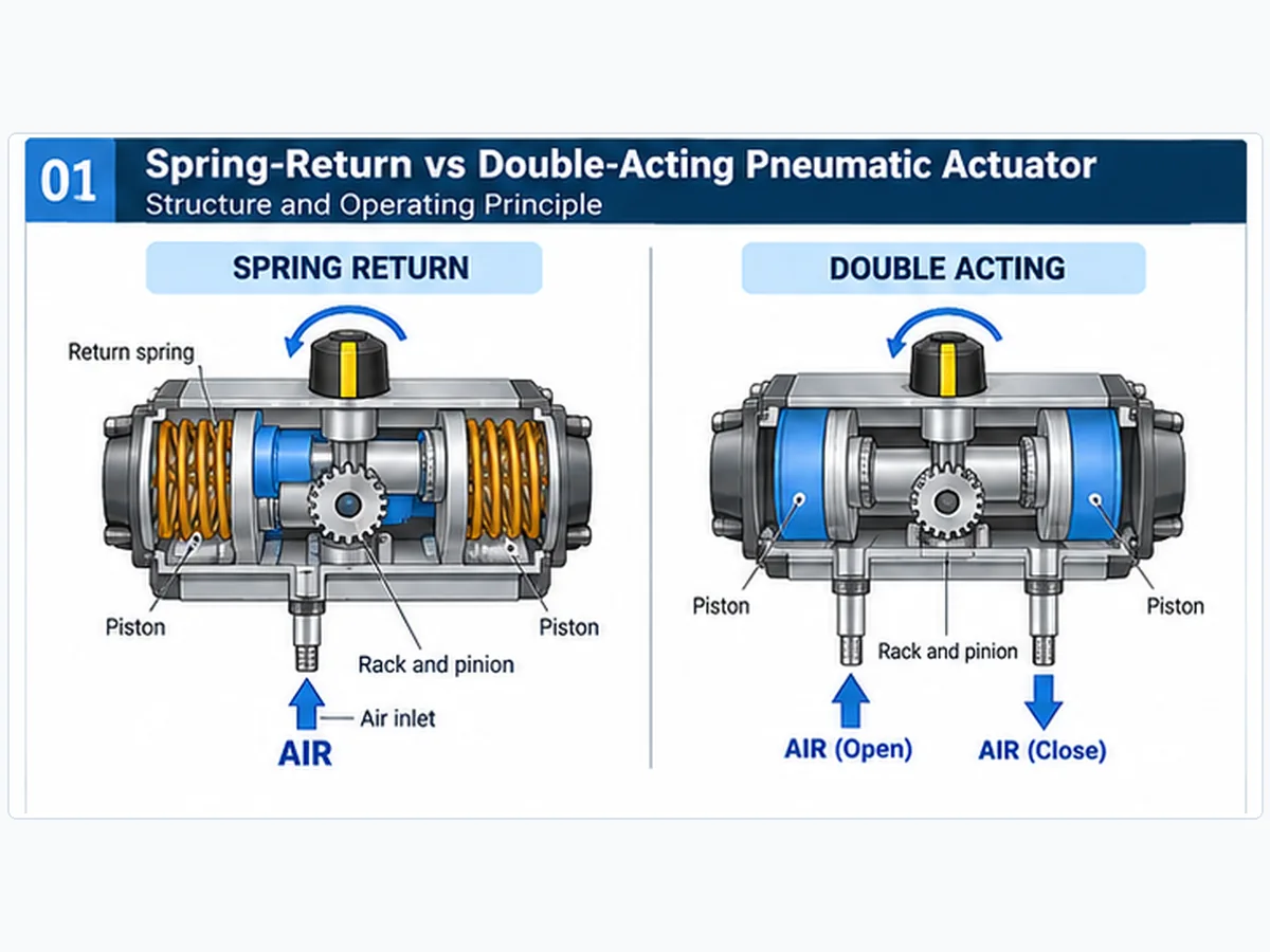
Both configurations can operate many industrial quarter-turn ball, butterfly and plug valves. Their fundamental difference is the energy used to move the valve and what may remain available when the normal air supply is lost. Spring-return and double-acting describe actuation configuration; rack-and-pinion and scotch-yoke describe mechanical conversion mechanisms.
| Fattore di selezione | Spring-return (SR) | Double-acting (DA) |
|---|---|---|
| Fonte di alimentazione | Air powers one direction; spring energy powers return | Air powers movement in both directions |
| Return mechanism | Mechanical spring assembly | No inherent mechanical return spring |
| Loss of air | Spring movement possible if the relevant pressure can exhaust and sufficient spring output remains | Response depends on chamber pressure, circuit, valve load and accessories |
| Posizione di sicurezza | Spring-to-open or spring-to-close, subject to assembly configuration | Not inherently fail-open, fail-closed or fail-in-place |
| Aria compressa | Supplied for powered stroke | Supplied for both powered strokes |
| Torque review | Separate air-stroke and spring-stroke output | Check available pneumatic torque in both directions |
| Actuator envelope | Spring package can increase size for a comparable duty | May be more compact for comparable requirements |
| Typical control valve arrangement | Often a three-way pneumatic control circuit | Often a five-way or equivalent directional circuit |
| Procurement basis | Fail-response requirement and output profile | Pneumatic control philosophy and output profile |
A larger spring-return actuator is not necessarily more air-efficient than a smaller double-acting model; likewise, double-acting does not always mean more torque or lower installed cost. Compare actual selected models against the same valve duty and assumptions.
Four Questions to Resolve Before Comparing Prices
- What should the complete valve package do following loss of air, electrical power, control signal or an emergency shutdown command?
- What torque or thrust is required at breakaway, during travel and near seating under governing conditions?
- What minimum and maximum instrument-air pressures and air delivery capacity are available at the actuator?
- What stroke time, operating frequency, accessories, testing and documentation are included in the quotation?
2. How Spring-Return and Double-Acting Actuators Work
Spring-Return: Pressure Stroke and Spring Stroke
In a typical spring-return actuator, compressed air moves a piston against a return spring. Spring compression stores mechanical energy. When the pressure holding the actuator against the spring is adequately relieved, the spring moves the actuator toward its designated return position. The mechanism must deliver sufficient torque not only at the beginning of the return stroke but also at the critical valve positions throughout travel.
I termini spring-to-close e spring-to-open describe the intended valve action. The actual outcome also depends on mounting, valve rotation, porting, venting, stops and the connected valve load.
Double-Acting: Pneumatic Movement in Both Directions
In a conventional double-acting actuator, a directional control circuit routes compressed air to alternate chambers to move the actuator in either direction while allowing the opposing volume to exhaust. Because there is no inherent spring return, an interrupted air supply does not independently define the shaft position. If pressure is trapped, released or supported by a reservoir, the response can differ.
Rack-and-Pinion vs Scotch-Yoke
Rack-and-pinion and scotch-yoke refer to mechanisms that convert piston force to rotary output. They can produce different torque-versus-angle characteristics. Actual curves depend on geometry, effective piston area, internal losses, spring characteristics and pressure. A spring-return designation alone does not establish the mechanism or the usable torque profile.
3. Fail Action: What Happens When Instrument Air Is Lost?
For an expanded failure-scenario and process-safe-state review, see Fail Open vs Fail Close Control Valve. This article remains focused on the spring-return versus double-acting mechanism and package-level selection.
Engineering review example — an emergency isolation valve: An RFQ may call for “fail closed” while the supplied valve turns in the opposite direction from the assumed actuator mounting. The specification can appear correct until package testing reveals the mismatch. Prevent this by checking the valve shaft closing direction, spring action, coupling orientation, minimum available spring torque at the required seating point and the solenoid exhaust path. A de-energized-solenoid test alone does not establish the response to every loss-of-air scenario.
Spring-to-Close Does Not Follow Automatically from Spring Return
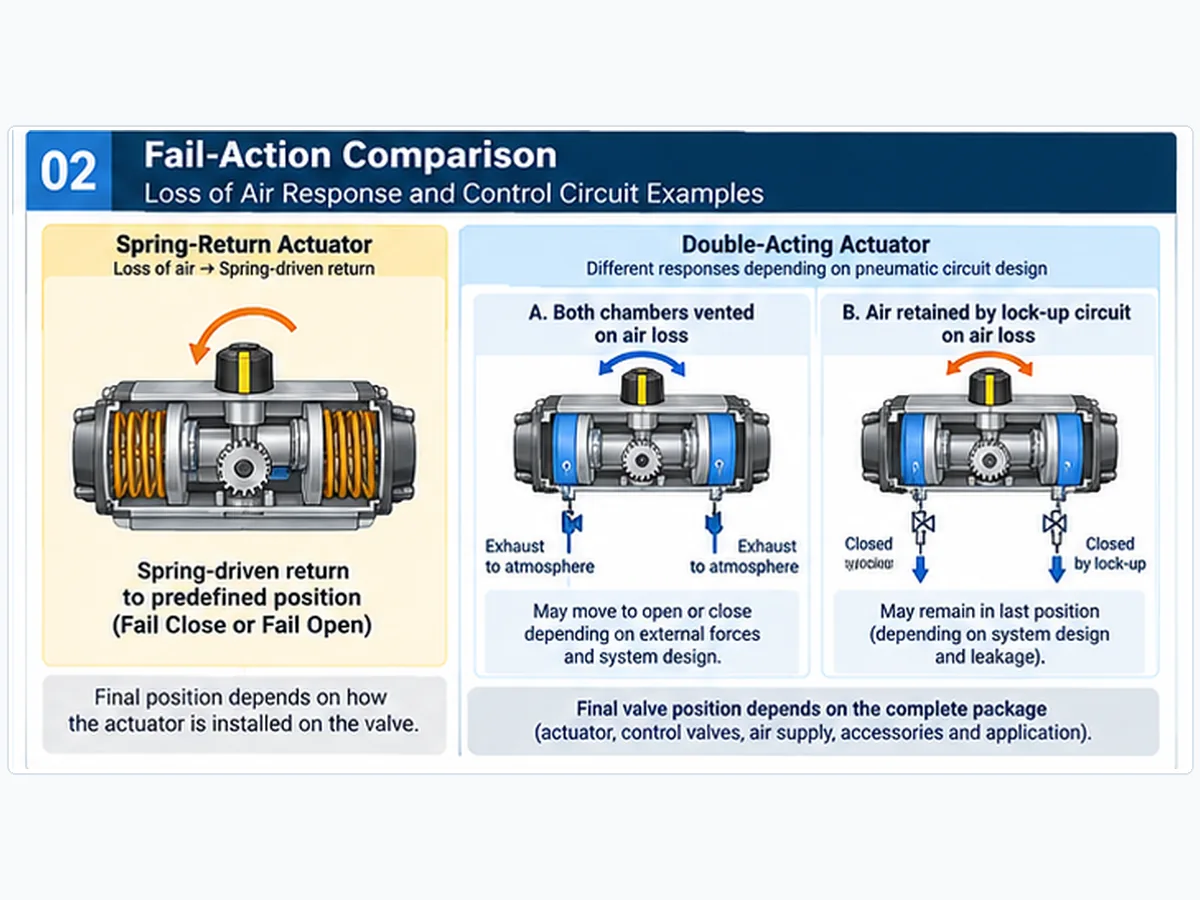
A spring-return actuator may be built or assembled to open or close the valve when spring energy is released. To verify its effect, confirm the valve stem rotation, actuator mounting and spring-action direction; review the solenoid exhaust path; and check that available spring torque over the full return stroke exceeds the relevant valve load.
Why Double-Acting Does Not Automatically Mean Fail-in-Place
A double-acting actuator may be connected to a circuit that vents both chambers, traps chamber pressure through lock-up devices or uses auxiliary stored pneumatic energy. These are different engineered configurations. Trapped air does not guarantee indefinite position holding: internal leakage, temperature changes and process forces can cause drift. A reservoir likewise requires engineering of usable pressure, consumption, sequence and load.
Distinguish Different Failure Events
| Scenario | What must be checked |
|---|---|
| Loss of instrument air | Chamber venting, stored pressure or spring energy, valve load and final position |
| Loss of solenoid electrical power | Normal solenoid state and actual pneumatic port connections |
| Loss of control signal | Positioner configuration and assigned fault response |
| Emergency shutdown demand | Shutdown logic, available energy, valve movement and travel time |
| Utility restoration | Restart or reset logic and unintended movement risk |
A successful de-energized-solenoid test does not by itself prove that a valve will respond identically to total loss of instrument air. The pneumatic drawing and complete assembly should be reviewed against each specified failure scenario. A return spring also does not by itself establish a certified safety integrity level.
For a wider treatment of failure philosophy, see the Raymon Valve valve actuation and drive-mode resource.
Failure-Response Verification: Required Evidence and Acceptance Points
A failure-response statement is not complete until the supplier specifies which fault is simulated, which pneumatic ports change state, which energy source moves the valve and how the final valve position is verified. The following acceptance matrix can be used during package documentation review; it does not replace a project-approved functional-test procedure.
| Scenario to demonstrate | Required supplier evidence | Acceptance question |
|---|---|---|
| Loss of instrument-air supply | As-built pneumatic schematic; spring/auxiliary-energy basis; governing valve load | Does the package achieve the specified final state within the agreed conditions and time? |
| Loss of electrical power to solenoid | Solenoid normal position, port map and reset logic | Does de-energization cause the intended air routing, rather than only the assumed actuator response? |
| Loss of control signal | Positioner configuration and documented fault setting | Does the actual signal-loss action satisfy the stated valve requirement? |
| Air lock-up / stored-air function | Reservoir capacity or lock-up philosophy, leakage assumptions and pressure limits | Is the specified travel or permitted position drift achievable over the required duration? |
| Air or power restoration | Reinstatement sequence and operating procedure | Can unexpected movement be prevented or managed through the approved reset logic? |
Verification boundary: functional testing of a particular demand case does not, by itself, prove the complete safety function, performance under every fault or compliance with a functional-safety standard. Applicable acceptance criteria are defined by the project and responsible engineering team.
4. Air Consumption: Which Configuration Uses Less Compressed Air?
Air-demand reporting basis: “Free air” or normal/standard volume must identify the applicable reference absolute pressure and temperature. Gauge supply pressure must be converted to absolute pressure before using pressure ratios (approximately local atmospheric pressure plus gauge pressure). The simple chamber-fill relation below assumes a defined initial chamber state, approximately isothermal ideal-gas behavior and no uncounted losses. If a chamber starts above atmospheric pressure, the incremental air supplied cannot be inferred from final chamber pressure alone. Solenoid, regulator, tubing and manifold volumes, exhaust routing, leakage and accessories require package-specific review. Average consumption per cycle, peak filling-flow demand needed to meet stroke time, and continuous bleed are three different specifications.
Procurement comparison example — operating frequency changes the result: Two offered actuators may quote different air-consumption figures because one supplier reports nominal litres at a reference condition and another reports the volume of compressed air in a chamber at operating pressure. Before using the data for operating-cost estimates, normalize the reference temperature and pressure, number of charged strokes per complete cycle, selected actuator size and cycling frequency. Separately verify instantaneous air-flow capacity to meet the specified stroke time.
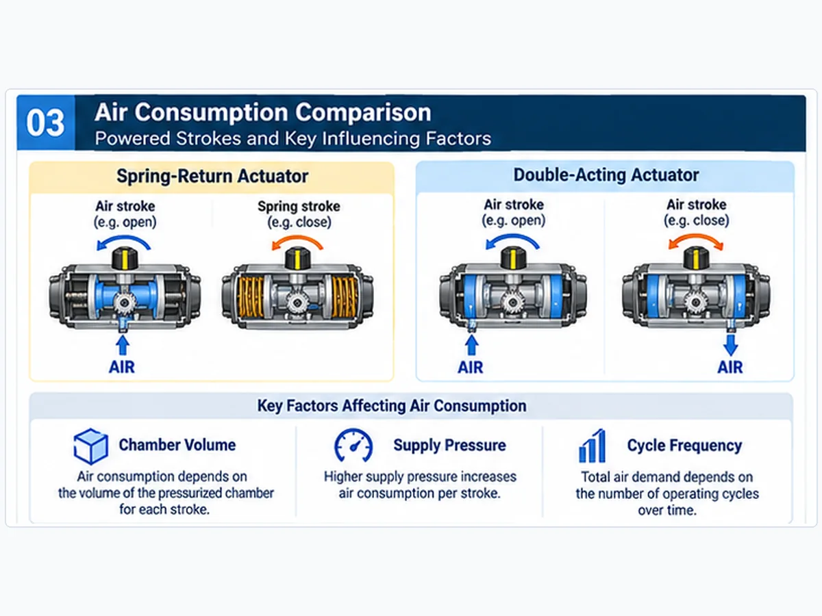
Spring-return units normally consume supplied air during one powered stroke, while double-acting actuators consume supplied air in both travel directions. This difference can reduce supply demand, but a fixed percentage saving is not defensible without the actual actuator volumes and operating conditions. A spring-return actuator may be larger because its air stroke must work against spring force.
Air Demand per Stroke and Complete Cycle
For a simplified ideal-gas comparison where a charged chamber begins near atmospheric pressure and reaches the stated absolute supply pressure, an approximate free-air-equivalent volume can be written as:
Here Vcharged,i represents the effective volume charged during a powered stroke, Pabs,i its absolute pressure and Pref the absolute reference pressure for normalized air reporting. Chamber starting pressure, tubing and manifold dead volume, venting, regulator effects and air leakage can make real consumption different.
For a specified number of cycles, estimated cycle-related free-air demand is the per-cycle value multiplied by the number of cycles. This excludes additional continuous demand from positioners, purge systems and leakage unless explicitly included.
How Buyers Should Compare Air Use
| RFQ information | Motivo |
|---|---|
| Exact actuator model | Confirms the compared chamber size and construction |
| Consumption per stroke and cycle | Enables a common comparison |
| Units and reference conditions | Distinguishes actual compressed volume from standardized free-air volume |
| Supply pressure | Affects consumption and available output |
| Cycles per hour/day | Converts per-cycle consumption into operating demand |
| Tubing, solenoids, positioners and purges | Identifies additional package consumption |
| Required opening and closing times | Checks available air flow as well as total demand |
For infrequently operated isolation valves, energy consumption may be a secondary consideration. For frequently cycling packages, air demand and plant air-system capacity can have a greater influence on operating costs. The project should decide the relative weighting.
Separate Air Volume, Air Flow and Continuous Consumption
Cycle consumption describes the total quantity of compressed air required over a defined operating cycle. It is different from instantaneous air-flow capacity, which influences whether the actuator can meet a specified stroke time. A package with acceptable total cycle consumption can still operate too slowly if tubing, solenoid flow capacity, regulators or supply restrictions limit delivery. A positioner, purge or leaking component may also create a continuous air demand that is not captured by actuator chamber-fill calculations.
For comparable bids, require suppliers to state the consumption unit and reference pressure/temperature, define whether one cycle means open-and-close movement, identify included accessory demand, and separately confirm the minimum effective pressure at the actuator during movement. If these fields differ, normalize the data before comparing operating costs.
5. Torque Output: Matching Actuator Capacity to Valve Load
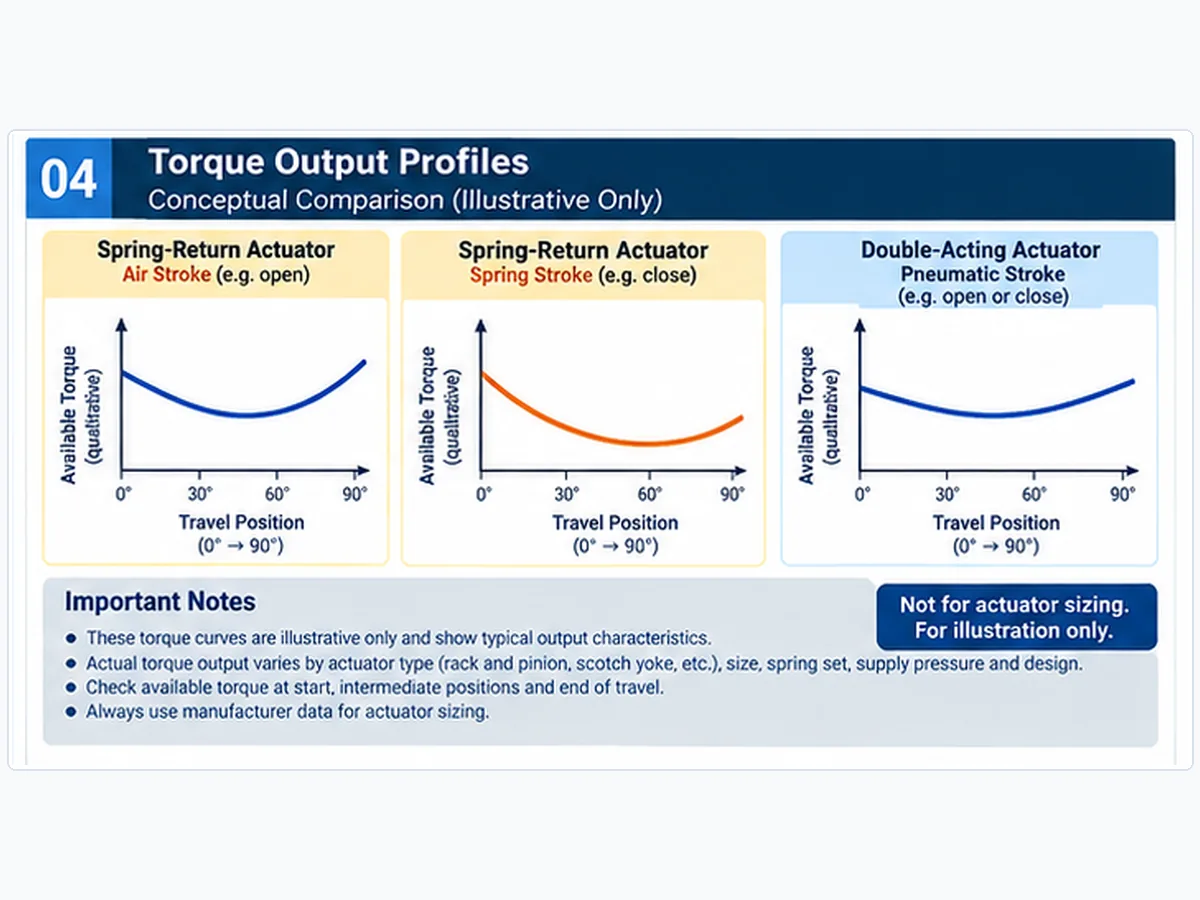
The critical sizing question is not which actuator has a higher catalog maximum torque. It is whether the selected actuator has adequate available output at each governing point in the required direction and under the correct pressure or spring-return condition.
Torque review example — breakaway is not the only load point: A supplier may propose an actuator because its maximum catalog output exceeds the valve opening breakaway torque. That does not prove the spring can seat the valve at the end of the fail-close stroke. Request position- and direction-specific required valve torque and the selected actuator’s available air-stroke and spring-stroke outputs at the governing conditions. Check maximum drive torque against the valve stem and mounting limits as well as minimum torque adequacy.
Breakaway, Running and Seating Torque
Coppia di spunto is required to initiate movement from a stationary or seated condition. Coppia di esercizio is required through intermediate travel. Seating or end-of-travel torque is required near the final position. Actual requirements depend on valve construction, differential pressure, seat behavior, temperature, fluid loads and friction. Use the valve manufacturer’s specific torque data for the exact offered valve.
Spring-Return Air and Spring Stroke Profiles
For a spring-return actuator, separate manufacturer output data are required for the air-powered stroke and the spring-powered stroke. Spring torque often changes as stored energy is released, and mechanical advantage can alter torque throughout travel. Sufficient output at one end does not prove adequate output at the other end. For spring-to-close service, end-of-closing spring torque can be decisive; for opening, pressure-driven breakaway capability may govern.
Double-Acting Output in Both Directions
Double-acting actuators deliver pneumatic torque in each direction, but their torque distribution across travel is model-specific. Idealized rack-and-pinion designs may be comparatively uniform; scotch-yoke mechanisms may have more variable mechanical advantage. Manufacturer output tables remain essential.
| Load point | Valve data | Actuator evidence |
|---|---|---|
| Break-to-open | Unseating or opening breakaway torque | Opening starting output |
| Run-to-open | Opening travel torque | Output through opening travel |
| End-to-open | Final opening load | Opening end output |
| Break-to-close | Applicable closing breakaway torque | Closing starting output |
| Run-to-close | Closing running load | Output through closing travel |
| End-to-close | Required seating load | Closing end output |
| Spring return after air loss | Valve load throughout failure stroke | Available spring output across required travel |
| Maximum supply condition | Permissible stem/drivetrain loading | Potential maximum actuator output |
The pressure-driven stroke must be checked at the minimum available pressure at the actuator. Maximum available pressure and actuator output should also be evaluated to avoid exceeding the valve stem, coupling or mounting hardware limits. Final sizing requires model-specific charts and responsible engineering approval—not an example curve from this article.
Manufacturer sizing basis: La Emerson Bettis actuator selection procedures describe identifying valve load by travel position and direction and reviewing pressure-stroke and spring-stroke outputs at the required supply conditions. This is a 2010 technical reference, not the current sizing approval for every model. Consult the exact proposed actuator’s current manufacturer torque-rating data, spring set and published conditions; these external examples do not establish the ratings or certifications of any Raymon Valve package.
Actuator Torque Review: Supplier Acceptance Checklist
Require a traceable torque review for the offered valve and actuator combination, not a catalog maximum output value without a matching load case. Review the following evidence before technical approval:
| Acceptance item | Evidence to obtain | Confine decisionale |
|---|---|---|
| Valve-load source | Valve manufacturer torque/thrust schedule for the specific valve, seat, differential pressure and service | Do not substitute torque from an unrelated valve model. |
| Minimum pneumatic pressure | Pressure available at actuator and output data at that pressure | Do not size at nominal plant-header pressure if a lower supply condition governs. |
| Air-powered stroke | Actuator output vs travel, direction and selected spring set where applicable | Check the full relevant travel, including start and final movement. |
| Spring-powered stroke | Return-stroke output curve or manufacturer values and documented venting basis | Verify sufficient output during the defined failure condition. |
| Excess output / allowable limits | Maximum pressure/output and permissible stem, coupling, bracket and gearbox loads | More torque is not automatically acceptable. |
| Selected margin | Documented sizing allowance and clear treatment of factors already included in load figures | Apply only the project-approved methodology. |
Stop condition: if the supplier cannot substantiate output at the governing pressure and travel positions, record the bid as requiring clarification rather than approving a larger-looking actuator from peak torque alone.
6. Spring-Return vs Double-Acting Selection Matrix
If the project has not yet chosen between pneumatic and electric energy sources, consult the related Pneumatic vs Electric Valve Actuator comparison. Here the pneumatic energy source is already assumed, and the decision concerns spring-return versus double-acting operation.
| Application need | Direzione preliminare | Mandatory checks |
|---|---|---|
| Defined spring-driven closure after relevant air loss | Evaluate spring-to-close SR | Required rotation, exhaust path and closing spring torque |
| Defined spring-driven opening after relevant air loss | Evaluate spring-to-open SR | Required rotation, exhaust path and opening spring torque |
| Bidirectional pneumatic operation without inherent return | Evaluate DA | Air availability and acceptable failure behavior |
| Desired position holding on air loss | Engineered DA circuit may be evaluated | Lock-up, leakage, process loads and allowable drift |
| High differential pressure or high seating load | Compare actual models | Valve-load profile and output at governing points |
| Limited installation envelope | Compare selected models | Dimensions, weight, mounting and maintenance access |
| Cicli frequenti | Evaluate both designs | Cycle duty, air capacity, consumption and maintenance |
| Rapid shutdown stroke | Project-specific package review | Energy availability, time requirement and functional test |
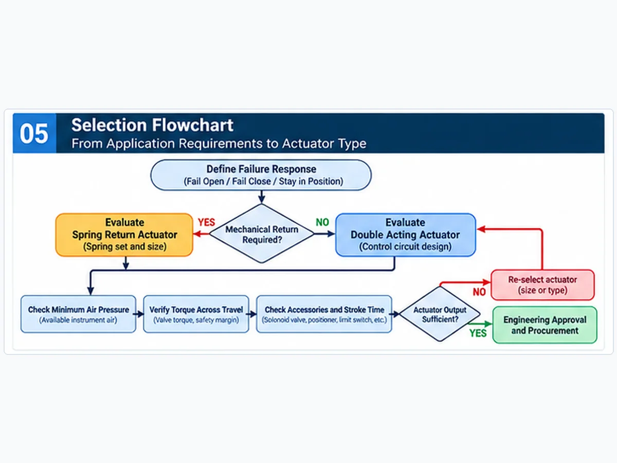
Selection path: define failure response → determine whether mechanical spring return is required → obtain valve torque/thrust data → establish minimum supply conditions → verify both travel directions → compare dimensions, accessories, stroke time and total cost → obtain technical approval. If a spring-return package cannot deliver the required return torque, revisit the engineered design rather than relaxing a mandatory failure requirement.
7. Accessories, Maintenance and Lifecycle Cost
Pneumatic Controls and Accessories
A spring-return package often uses a suitable three-way directional circuit; a double-acting package commonly uses a five-way or equivalent configuration. The correct solenoid porting and de-energized state must be verified for each installation. Positioners, regulators, filters, limit switches, quick-exhaust devices, speed controls and tubing can change the complete package response and must be included where specified.
Maintenance and Stored Energy
Both configurations require inspection and maintenance of pneumatic seals, bearings, linkages, connections and controls in accordance with the manufacturer instructions. A spring-return assembly also contains potentially hazardous stored mechanical energy, which must be addressed in approved isolation and disassembly procedures. Neither configuration is inherently maintenance-free.
Total Installed Package Cost
Compare actuator purchase cost, mounting and couplings, solenoid and instrument-air accessories, installation space, air use, maintenance tasks, spare parts, functional-test scope and downtime exposure. Cost conclusions require consistent service life and duty assumptions; no universal lowest-cost actuator type can be established.
8. Pneumatic Actuator RFQ Checklist
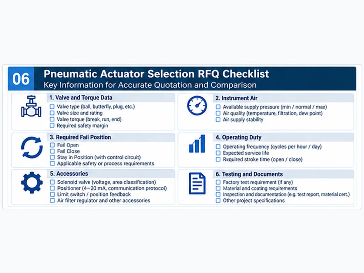
Suppliers cannot quote comparable actuator packages when valve-load data, failure response or accessory requirements are ambiguous. Request the information below on a common technical basis.
Bid-evaluation example — complete package scope: Two quotations marked “spring-return, fail closed” may differ materially: one includes a solenoid, filtered air supply, limit switches and a defined loss-of-air functional test, while the other quotes only the actuator body. Normalize accessory scope, loss-of-power and loss-of-air scenarios, required stroke time, torque verification and delivered records before treating the prices as comparable.
| Field group | Minimum information to provide or request |
|---|---|
| Identificazione valvola | Type, model, size, pressure class, service, required shaft rotation |
| Valve operating loads | Torque/thrust by direction and travel position; governing differential pressure |
| Maximum allowable load | Stem, coupling, bracket and drivetrain load limits |
| Supply-air conditions | Minimum/normal/maximum pressure at actuator; required air quality and capacity |
| Failure philosophy | Required position for loss of air, power and signal; shutdown sequence |
| Ciclo operativo | On-off/modulating, cycles, opening/closing stroke times |
| Consumo d'aria | Per-stroke/per-cycle data with units, pressure and reference conditions |
| Accessori | Solenoid, positioner, limit switches, regulator, lock-up, reservoir and fittings |
| Interfaccia meccanica | Mounting standard, orientation, coupling, envelope and clearance |
| Documentation and acceptance | Output chart, sizing review, pneumatic schematic, drawings, inspection/test scope and deviations |
Technical bid comparisons should distinguish a bare actuator from a complete assembled and tested valve package. The bid should identify exclusions and deviations explicitly; spring set, operating pressure, pneumatic circuit, documentation and testing need consistent comparison criteria.
How to Evaluate Supplier Actuator Packages Before Purchase Approval
Use the RFQ fields above to normalize bids, then classify each proposed package as technically acceptable, clarification required o technical deviation requiring approval. These are review states, not certification or proof of product quality.
| Bid review checkpoint | Evidence / comparison basis | Action if absent or inconsistent |
|---|---|---|
| Actuator identity | Exact model, spring set if relevant, mechanism, output chart and bill of materials | Request complete actuator identification. |
| Torque verification | Offered valve loads matched to air/spring output by direction and travel | Hold technical approval for engineering clarification. |
| Failure-response scope | Defined air, electrical and signal failure cases; schematic and acceptance criteria | Record missing function as a technical deviation. |
| Pneumatic demand | Air consumption and air-flow requirement on the common RFQ basis | Normalize units and package inclusions. |
| Package completeness | Solenoids, positioner, switches, regulator, mounting, coupling and tubing | Separate included items from optional/excluded items. |
| Testing and handover | Approved functional tests, travel-time checks, drawings and documentation package | Agree acceptance and deliverables before purchase order. |
Ask suppliers to list all deviations and exclusions in one schedule, including differences in minimum air pressure, fail position, duty cycle, accessories, test scope and document deliverables. A lower-priced proposal should not be assumed equivalent until these differences have been resolved.
9. Frequently Asked Questions
What is the main difference between spring-return and double-acting pneumatic actuators?
A spring-return actuator uses compressed air for one direction and spring energy for the return movement. A double-acting actuator uses compressed air in both directions. Selection depends on failure-response requirements, valve loads, available air and the complete control circuit.
Does a spring-return pneumatic actuator always fail closed?
No. Spring-return actuators may be arranged for spring-to-close or spring-to-open action. Actual response depends on valve rotation, mounting, spring output, pneumatic venting and connected valve loads.
What happens to a double-acting actuator when air supply is lost?
Its response depends on whether pneumatic pressure is vented, trapped or supplied from stored air, as well as process forces and leakage. Double-acting does not automatically mean fail-in-place.
Does a spring-return actuator consume less compressed air?
It may, because normal operation only requires air supply for one stroke. Actual consumption also depends on selected actuator size, chamber volumes, pressure, accessories and cycle rate; fixed percentage savings should not be assumed.
Which actuator provides more torque?
Neither configuration universally provides more usable torque. Compare position- and direction-specific output curves with valve breakaway, running and seating torque at governing conditions.
What information is needed for pneumatic actuator selection?
Provide valve identification, governing torque or thrust data, differential pressure, shaft rotation, minimum and maximum instrument air, required fail position, duty, stroke times, accessories and testing/documentation requirements.
10. Final Selection Recommendations
Consider spring-return when a defined mechanically powered return movement is required and the spring package can overcome the specified valve load. Consider double-acting when air-driven movement in both directions is acceptable and the complete circuit meets the specified failure philosophy. Neither configuration should be approved from a single peak torque figure, a generic “fail-safe” label or actuator purchase price alone.
The most defensible comparison evaluates the full valve-actuator package against common air-supply, torque, failure, operation and documentation requirements. For broader package choices, review control valve options and the valve actuation selection resource.
Request Actuator Torque Review
For a comparable spring-return or double-acting package review, send the valve model and torque/thrust schedule, governing differential pressure, required valve rotation, minimum/normal/maximum air pressure at the actuator, defined failure scenarios and acceptance position, stroke time, cycle rate, accessory list and documentation scope. Ask for the supplier’s torque matching evidence, pneumatic schematic and explicit technical deviations. Final sizing and any safety-function requirements remain subject to project engineering approval.
Request Actuator Matching Support →Engineering Assumptions and Limits
This article supports preliminary industrial pneumatic actuator comparison, mainly for quarter-turn valve assemblies. Figures show engineering concepts, not Raymon Valve product-specific internal designs, certified failure responses or measured torque data. Actual actuator selection requires approved valve torque/thrust information, manufacturer output data, project operating conditions, applicable specifications and engineering approval. Spring-return functionality alone does not prove SIL or functional-safety compliance. Request model-specific manufacturer output charts and actual project test records where needed; this article and its conceptual illustrations are not substitutes for these documents.
 Italian
 English
 German
 Arabic
 French
 Spanish
 Portuguese
 Russian