
Check Valve Sizing & Operating Approval
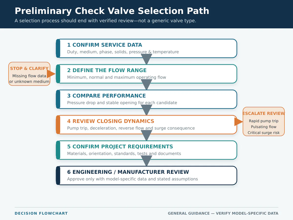
Check valve sizing requires more than matching the nominal valve size to the pipe. The proposed model must pass the required flow at an acceptable pressure loss, remain sufficiently open and stable at minimum and normal flow, and close appropriately as forward flow decelerates. The review should therefore use exact-model performance data together with the medium, pressure, temperature, orientation, pump sequence and system transient risk.
Pipe size defines the connection. Minimum stable flow, exact-model pressure drop and closing behavior determine whether the valve is suitable for the duty.
Why Line Size Is Only a Starting Point
Nominal pipe size defines the mechanical interface, including the end connection and installation envelope. It does not establish:
- Pressure drop at minimum, normal or maximum flow;
- Whether the disc, plates, piston or poppet will reach a stable open position;
- How the closure element responds during pump or compressor shutdown;
- Whether the valve will chatter under low, pulsating or fluctuating flow;
- Whether closing behavior is suitable for the system deceleration rate;
- Whether body, trim and seat materials suit the medium and temperature;
- Whether testing and documentation meet the purchase specification.
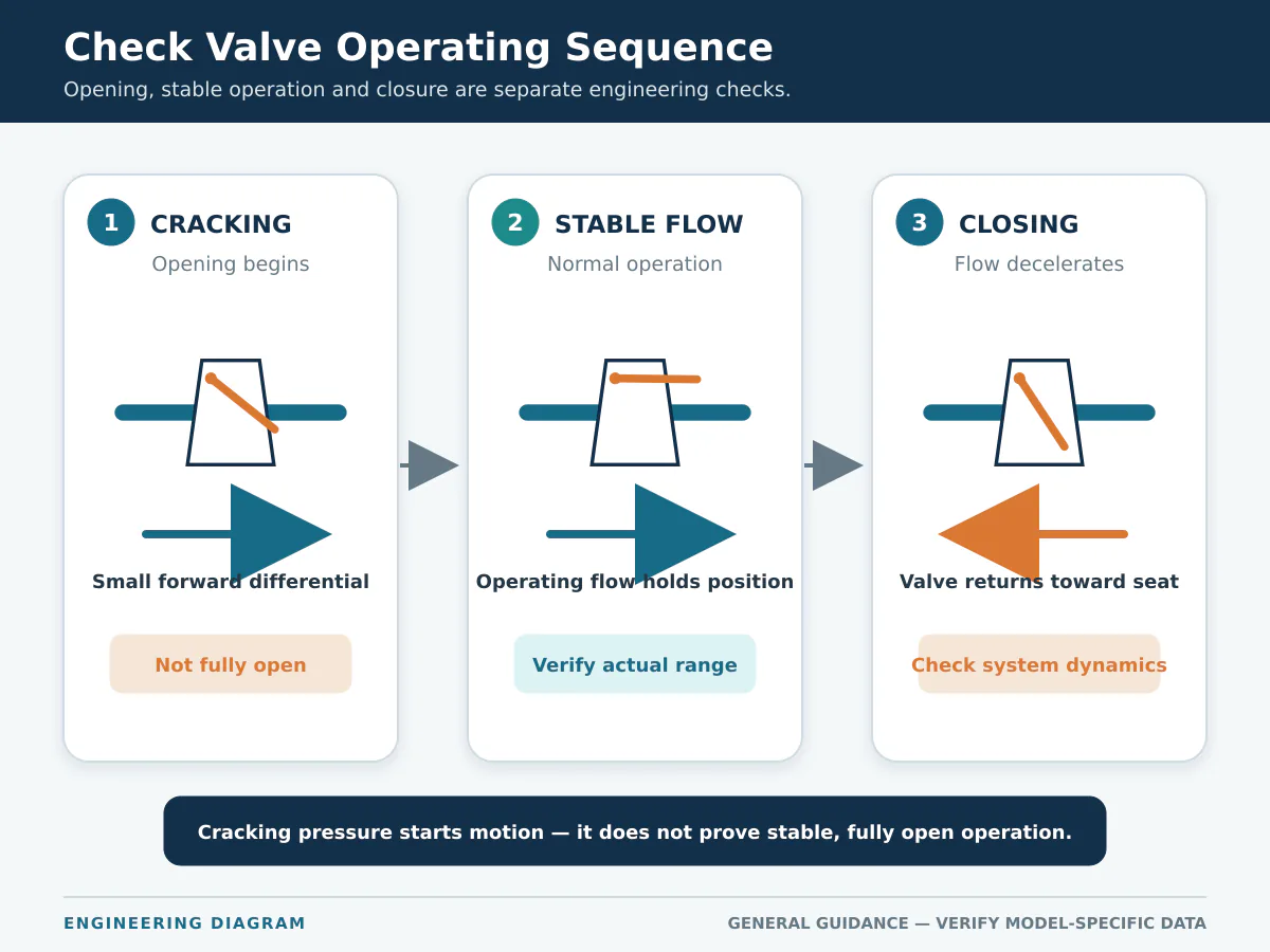
Because a check valve is self-acting, differential pressure and fluid forces govern its internal movement. Mechanical fit therefore does not confirm stable operation.
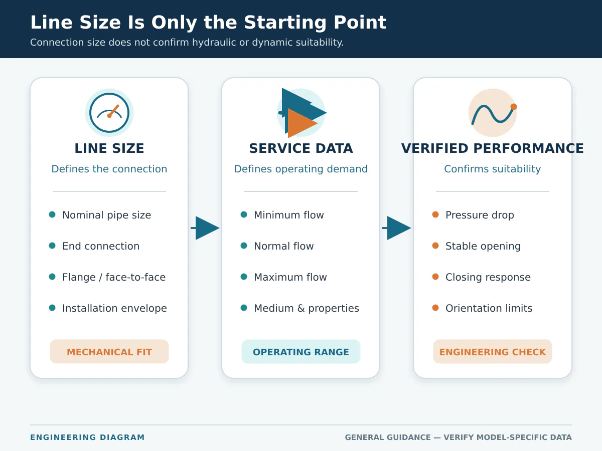
A line-size valve may be suitable, but only after the operating conditions are checked. Review available constructions in the check valve product range, then confirm the proposed model against the complete datasheet.
What Check Valve Sizing Actually Means
Check valve sizing is not limited to finding a bore large enough to pass maximum flow. It requires a balance among flow capacity, stable opening, pressure loss and closing response.
Passing the Required Flow
The valve must pass maximum flow without unacceptable pressure loss, but minimum and normal flow can control the selection when variable demand, parallel pumps or intermittent operation leave the closure element only partly open.
Maintaining Stable Opening
A disc, plate, piston, ball or poppet that is not held in a stable position may flutter or chatter. Oversizing is one possible contributor; disturbed inlet flow, pulsation, spring force, orientation and rapid demand changes also matter. Industry guidance from Valve Magazine distinguishes velocity-sensitive swing or double-door designs from spring-loaded designs that may require a model-specific pressure-drop calculation.
Controlling Pressure Loss
Reducing valve size may improve opening stability while increasing pressure loss. Increasing size may reduce a fully open calculation while leaving the valve partially open at normal duty. A high published Cv or Kv is not automatically better when the operating point does not reach the position used to establish that value.
Reviewing Closing Response
Closing response depends on flow deceleration, closure travel, moving mass, friction, spring assistance, damping, pump shutdown and interaction with parallel equipment. Reverse flow stopped by the closing valve can contribute to a pressure surge. The ASME PVP paper on check valves in unsteady flow supports evaluating valve behavior with the connected liquid system rather than relying on steady-state pressure loss alone.
Three Review Scenarios That Line-Size Matching Misses
The following are typical engineering review scenarios, not Raymon Valve customer case claims. Each one shows why symptom, cause and verification should be connected before a valve is approved or replaced.
Low-Flow Chatter in a Line-Size Swing Check Valve
Problem: repeated tapping is reported during low-demand operation.
Likely cause direction: the disc may remain in an unstable partly open position because minimum flow is below the model’s stable operating range; pulsation or disturbed inlet flow may intensify the motion.
Verification and prevention: compare actual flow history with model-specific stable-opening guidance, inspect hinge and seat wear patterns, review the upstream layout and confirm whether a smaller size or different construction can meet both pressure-drop and dynamic requirements.
Parallel-Pump Shutdown Produces a Slam Event
Problem: normal running pressure drop is acceptable, but a loud event occurs when one pump trips while another remains online.
Likely cause direction: common-header interaction may create rapid reverse flow before a long-travel closure element reaches the seat.
Verification and prevention: review the pump trip sequence, pressure trace, header pressure, pipeline profile and valve dynamic characteristic. When consequence is significant, complete a system transient assessment rather than selecting only from a “non-slam” product label.
High Published Cv but Excessive Field Pressure Loss
Problem: the quotation shows a high Cv, yet measured differential pressure is greater than expected.
Likely cause direction: the published value may represent a fully open valve while the actual operating flow holds the closure element in a smaller effective opening; deposits or inconsistent fluid-property assumptions may also contribute.
Verification and prevention: normalize the calculation basis, compare measured flow and differential pressure with the exact-model curve, inspect the internal condition and confirm expected valve position at minimum, normal and maximum flow.
Service Data Required Before Sizing
The following information should be available before a supplier makes a final recommendation.
| Required input | Why it matters |
|---|---|
| Valve duty and installation location | Defines the reverse-flow consequence to be controlled. |
| Medium, phase and composition | Influences flow review, materials and internal construction. |
| Solids or fouling tendency | May affect clearances, movement, erosion and seating. |
| Minimum, normal and maximum flow | Establishes the real operating range and possible partly open conditions. |
| Operating and design pressure | Supports system review and pressure-boundary selection. |
| Operating and design temperature | Affects materials, seats and pressure-temperature ratings. |
| Pipe size and connection standard | Defines the mechanical installation interface. |
| Allowable pressure drop | Helps screen valve size and internal construction. |
| Installation orientation | May affect gravity- or spring-assisted operation. |
| Pump or compressor operation | Influences flow deceleration, reverse flow and closing response. |
| Surge or reverse-flow risk | Determines whether system-level dynamic analysis is needed. |
| Leakage and specification requirements | Defines seat, testing and documentation expectations. |
RFQ boundary: pipe size, pressure class and quantity may be enough to quote a mechanically compatible valve, but those fields do not demonstrate stable operation, acceptable pressure loss or suitable closing performance.
A Step-by-Step Check Valve Sizing Process
Define the Non-Return Duty
Identify whether the valve protects a pump or compressor, prevents reverse drainage, limits cross-flow between parallel equipment, retains a liquid column or separates process streams. Record the consequence of delayed or incomplete closure.
Establish the Operating Flow Envelope
Record minimum, normal and maximum flow, plus startup, shutdown and relevant upset conditions. For parallel equipment, check one-unit and multiple-unit operation and the common-header pressure.
Review Pressure Drop
Use actual fluid properties and exact-model performance data. Compare suppliers on a consistent basis and confirm whether Cv or Kv assumes a fully open valve.
Check Opening Stability
Request guidance on stable operating range, expected closure-element position, cracking pressure where relevant, spring options, pulsating-service restrictions and orientation. Record missing performance data as a selection uncertainty rather than assuming the valve will remain fully open.
Review Closing Dynamics
Consider pump trip, pipeline length, velocity, elevation, parallel equipment, surge vessels and previous slam problems. Critical services may require a system transient analysis.
Confirm Size and Construction Together
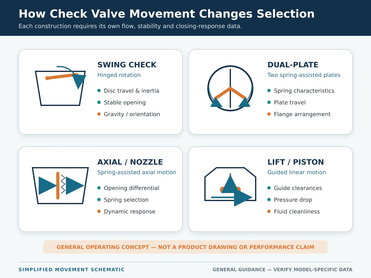
Swing, dual-plate, axial-flow and lift check valves can have different opening forces, travel, pressure loss and closing response. Evaluate each candidate with its own data.
How Check Valve Design Affects Selection
Swing Check Valves
A hinged disc rotates away from the seat. Review disc mass, travel, flow required to hold it open, orientation, maintenance space and response during rapid flow reversal.
Dual-Plate Check Valves
Two spring-assisted plates provide a compact arrangement. Check spring characteristics, pressure loss, plate stability, flange compatibility and wear under fluctuating flow.
Axial-Flow or Nozzle Check Valves
A spring-assisted disc generally moves along the pipeline axis. Confirm opening differential, pressure loss, stable range, fluid cleanliness, dynamic response and maintenance access.
Lift or Piston Check Valves
A guided element moves within the body. Review pressure drop, differential pressure, orientation, guide clearances, deposits and suitability for pulsating service.
Terminology boundary: terms such as “silent” or “non-slam” describe a design intention. They do not guarantee surge-free operation in every piping system.
Preliminary Selection Matrix
| Operating condition | Initial screening direction | Required engineering check |
|---|---|---|
| Stable continuous flow | Several constructions may be suitable. | Pressure drop and stable opening. |
| Wide flow variation | Review designs with a documented operating range. | Minimum stable flow and expected opening position. |
| Frequent starts and stops | Compare closure travel and assistance. | System deceleration and surge. |
| Pulsating flow | Avoid a generic type recommendation. | Dynamic suitability and fatigue risk. |
| Limited installation space | Screen compact constructions. | Maintenance access and piping loads. |
| Vertical pipeline | Check exact-model orientation limits. | Gravity, spring and flow direction. |
| Solids or fouling medium | Review clearances and seat exposure. | Blockage, erosion and incomplete closure. |
| Low allowable pressure drop | Compare exact performance curves. | Stability versus pressure-loss trade-off. |
| Parallel pumps | Review common-header interaction. | Cross-flow and shutdown sequence. |
| Critical surge consequence | Require a system-level assessment. | Transient model and valve dynamic data. |
This matrix supports preliminary screening only. It does not replace an approved datasheet, exact-model performance data or project engineering review.
When System-Level Engineering Review Is Needed
Move beyond a generic type or line-size recommendation when the service includes rapid pump trip, a long liquid pipeline, high operating velocity, large elevation change, multiple pumps on a common header, a critical surge consequence, pulsating compressor discharge, compressible or two-phase flow, or missing model-specific dynamic-performance data.
Steady-State Screening vs Dynamic Approval
| Preliminary steady-state screening | Project-level dynamic approval |
|---|---|
| Minimum, normal and maximum operating flow | Startup, shutdown, trip and upset scenarios |
| Exact-model pressure drop at stated conditions | System pressure and flow response over time |
| Expected opening position or stable-flow guidance | Valve dynamic characteristic and reverse velocity at closure |
| Installation orientation and nearby piping arrangement | Pipeline profile, pump or compressor behavior and boundary conditions |
| Supplier performance data and declared assumptions | Service-appropriate transient model, acceptance criteria and responsible engineering approval |
This separation prevents a steady-state Cv/Kv calculation from being treated as proof of acceptable shutdown or reverse-flow behavior.
Problems Caused by Line-Size-Only Selection
Line-size-only selection can contribute to chatter, excessive pressure loss, slam or reverse leakage, but each symptom has multiple possible causes. Use operating history and physical evidence before changing valve size or construction.
Failure Indications and What to Verify
Observed symptoms should be treated as investigation inputs rather than automatic proof of one failure cause.
| Observed indication | Possible contributors | Evidence to check | Review direction |
|---|---|---|---|
| Repeated tapping or chatter during operation | Low flow, oversizing, pulsation, disturbed inlet flow or unsuitable spring force | Actual flow history, valve position, upstream layout, spring data and internal wear pattern | Recheck stable operating range and installation before changing size |
| Loud event after pump shutdown | Reverse velocity, delayed closure, long travel or system pressure transient | Pump trip sequence, pressure trace, pipeline profile, valve dynamic data and closure condition | Assess system deceleration; perform transient analysis when consequence is significant |
| Higher-than-expected pressure loss | Undersizing, incomplete opening, deposits or inconsistent Cv/Kv basis | Measured differential pressure, actual flow, fluid properties, internal condition and exact-model curve | Normalize calculations and confirm the real opening position |
| Reverse leakage when closed | Debris, seat damage, wear, misalignment or unsuitable acceptance criterion | Seat condition, cleanliness, installation alignment and applicable seat-test record | Separate mechanical closure, seat condition and specified allowable leakage |
| Frequent spring, hinge or guide damage | Repeated unstable motion, pulsation, corrosion, erosion or unsuitable materials | Failure location, cycle history, medium composition, solids, velocity and material records | Review both operating dynamics and material compatibility |
Installation Factors That Can Change Performance
Orientation
Do not assume every check valve can be installed in any position. Gravity, spring force, closure travel and flow direction can change behavior. Use the approved drawing and instructions for the exact model.
Disturbed Flow
Elbows, tees, pumps, control valves and other fittings can create non-uniform flow that affects stability. There is no universal straight-pipe rule for every design; follow the product instructions and review the actual piping arrangement.
Parallel Equipment
When one pump or compressor starts, stops or remains on standby, the valve may see conditions not represented by the normal design point. Include common-header pressure, control sequence and possible cross-flow.
Maintenance Access
Consider cover removal, internal access, lifting space, valve weight, piping restraint and the shutdown required for removal.
Standards, Testing and Documentation
Standards establish design and acceptance requirements, but they do not replace application sizing. Review the project requirements alongside the Raymon Valve valve standards overview, while using official sources to confirm current editions and scope.
- API Standard 594, 9th Edition: API’s current updates page lists the 9th Edition notification for check valves. The standard applies to the check-valve constructions and end arrangements within its defined scope. It does not provide an exact-model pressure-drop curve, a universal minimum stable flow or proof of acceptable system transient response.
- ASME B16.34–2025: covers pressure-temperature ratings, dimensions, tolerances, materials, nondestructive examination requirements, testing and marking for valves within its scope. It does not establish model-specific opening stability, pressure loss or closing dynamics.
- ISO 5208:2015: remains current after ISO’s 2025 review and specifies examinations and tests used to establish pressure-boundary integrity, closure tightness and structural adequacy of the closure mechanism for industrial metallic valves. It does not establish operating-flow stability, pressure-drop performance or transient closing suitability.
Testing requirements and acceptance criteria should be defined rather than treated as interchangeable. Use the applicable project specification and current official test standard to define shell, closure or seat testing, witness points and acceptance criteria.
Supplier Evidence to Request Before Technical Approval
Project approval should rely on exact-model documents, defined inspection and test requirements, and the supplier evidence requested below.
| Selection statement | Supplier evidence to request | What it supports | What it does not prove |
|---|---|---|---|
| The proposed valve can pass the design flow | Exact-model Cv/Kv or pressure-drop curve, fluid basis and pressure drop at minimum, normal and maximum flow | Calculated capacity and pressure loss | Stable opening at minimum flow |
| The valve will operate across the stated range | Opening characteristic, cracking pressure where relevant, fully open flow basis and validated stable-flow guidance | Preliminary operating-range review | Surge-free shutdown in the actual piping system |
| The construction suits the closing duty | Closure travel, moving-element and spring data, plus reverse-velocity-versus-deceleration characteristics when available | Comparison of candidate closing behavior | A complete system transient result |
| Materials suit the specified service | Bill of materials, material specifications, MTC scope and compatibility review basis | Traceable construction and review assumptions | Universal corrosion resistance |
| Testing meets the purchase requirement | ITP, test procedure, acceptance criteria, witness points and sample report format | Defined inspection and acceptance scope | Application suitability or dynamic performance |
| The quotation matches the requested scope | Completed datasheet, drawing, document index, exclusions and technical deviation list | Technical bid normalization and approval basis | Performance beyond the submitted evidence |
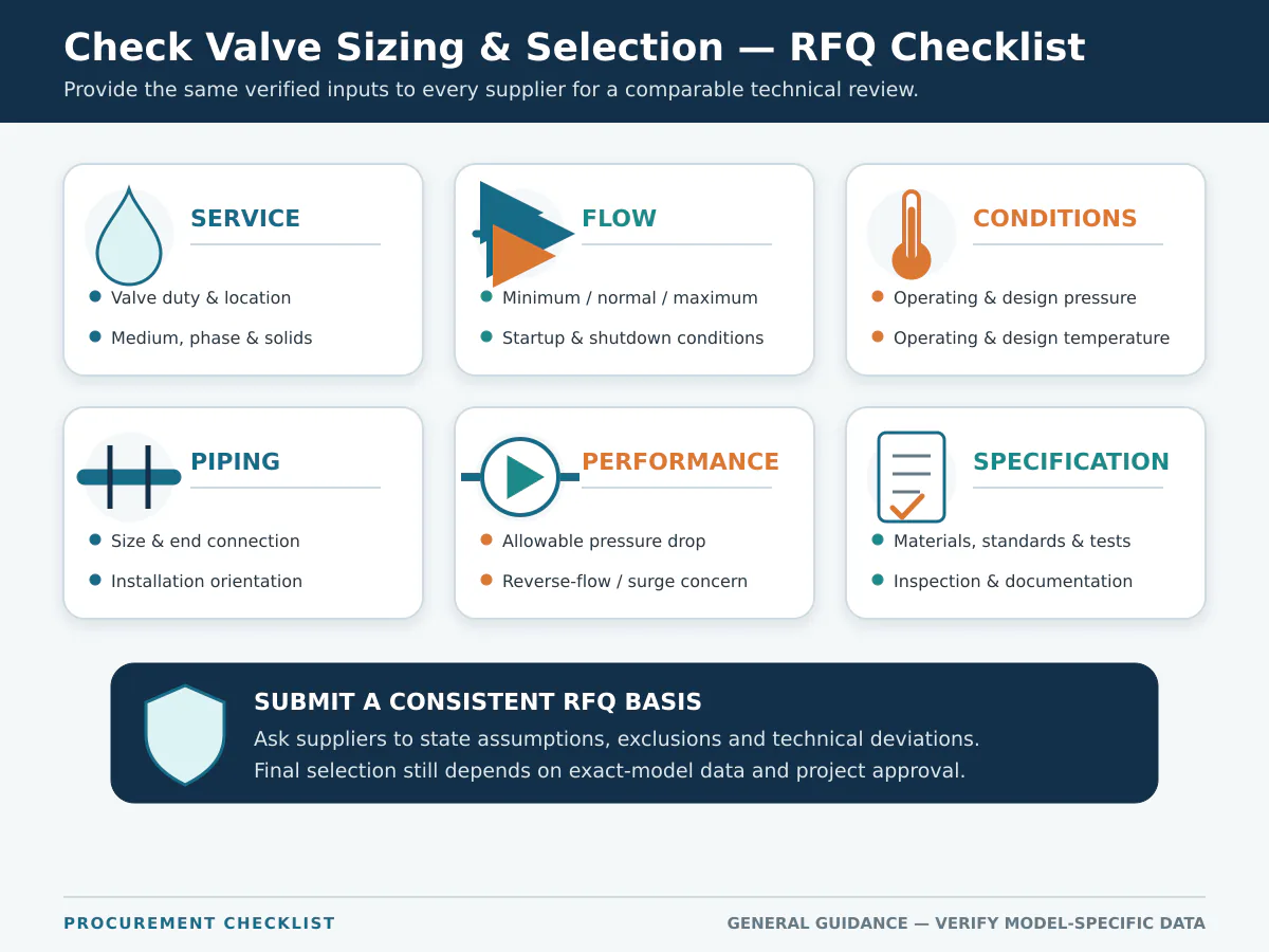
Check Valve RFQ Checklist
- Valve function and installation location;
- Medium, composition, phase and solids;
- Minimum, normal and maximum flow;
- Operating and design pressure;
- Operating and design temperature;
- Pipe size and end connection;
- Pressure class or PN;
- Installation orientation;
- Allowable pressure drop;
- Pump or compressor operating sequence;
- Known reverse-flow or surge concern;
- Body, trim and seat requirements;
- Leakage acceptance criteria;
- Applicable product and test standards;
- Inspection and witness requirements;
- Documentation, quantity and schedule.
Final Selection Principle
A reliable review connects four questions:
- Can the valve pass the required flow at an acceptable pressure loss?
- Will the closure element remain stable across the real operating range?
- Will its closing response suit system deceleration and reverse-flow behavior?
- Do its materials, ratings, testing and documentation meet the project requirements?
A preliminary article cannot replace model-specific sizing, material review, transient analysis or responsible-engineer approval. Supplier capability claims should be checked against current, scope-specific evidence during technical bid review.
Request a Check Valve Selection Review
Send the valve datasheet, line list or available P&ID together with the duty, medium, minimum, normal and maximum flow, operating and design pressure, temperature, line size, orientation, allowable pressure drop, pump or compressor sequence, materials, standards and required tests.
Ask the supplier to return the proposed type and size, sizing assumptions, missing data, exact-model pressure-drop and stable-opening basis, closing-response evidence where relevant, material scope, test and document inclusions, and a clear technical deviation list.
Request a Check Valve ReviewFrequently Asked Questions
Should a check valve be the same size as the pipe?
Not necessarily. Pipe size defines the connection, but the valve must also be checked against actual flow, allowable pressure drop, opening stability and closing response. A line-size valve may be suitable, but that conclusion requires exact-model performance evidence.
What information is needed to size a check valve?
At minimum, provide the medium, minimum, normal and maximum flow, operating pressure and temperature, pipe size, orientation and allowable pressure drop. Pump behavior, surge risk, materials, standards and testing may also be required.
What is the difference between cracking pressure and fully open flow?
Cracking pressure is the differential pressure at which the valve begins to open. It does not mean the valve is fully open or stable. Additional flow and differential pressure may be required to hold the closure element in its intended position.
Can an oversized check valve cause chatter?
Yes. If operating flow is too low to hold the closure element stable, it may repeatedly move or strike its limits. Installation conditions, pulsation, spring force and disturbed flow should also be investigated before changing valve size.
Does a higher Cv always mean a better check valve?
No. A higher Cv indicates greater flow capacity under the stated test or calculation condition, but it does not confirm stable operation or suitable closing dynamics. Confirm the basis of the value and the expected opening position at the real operating flow.
Which check valve is least likely to slam?
There is no universal answer. Closure travel, inertia, spring assistance and damping affect the valve, while pipeline length, pressure, velocity, pump sequence and flow deceleration affect the system. They must be evaluated together.
Can a check valve eliminate water hammer?
A properly selected valve may reduce some surge risks, but it cannot guarantee that water hammer will be eliminated. Critical liquid systems may require transient analysis and additional surge-control measures.
Can a check valve be installed vertically?
Some models can, but permitted flow direction and orientation depend on the exact construction. Confirm the manufacturer’s approved drawing and installation instructions against the project piping arrangement.
Engineering Note
Purpose: This guide supports preliminary check valve screening, RFQ preparation and technical bid comparison.
Assumptions and limits: No project-specific medium, flow, pressure, temperature, piping transient or exact-model performance data were supplied. The tables and scenarios identify review logic and required evidence; they do not approve a valve size or construction.
Project confirmation: Final selection should be confirmed against the complete datasheet, applicable project specification, model-specific manufacturer data and responsible engineering review. Critical liquid systems may require hydraulic transient analysis.
Content attribution: Prepared by the Raymon Valve Technical Content Team. No individual licensed engineer or independent reviewer is claimed for this page.
Technical scope: final selection depends on confirmed process data, exact-model performance, applicable project specifications and responsible engineering review. Standards and acceptance criteria vary by valve design, project and jurisdiction.
 English
  German
  Arabic
  French
  Spanish
  Italian
  Portuguese
  Russian