
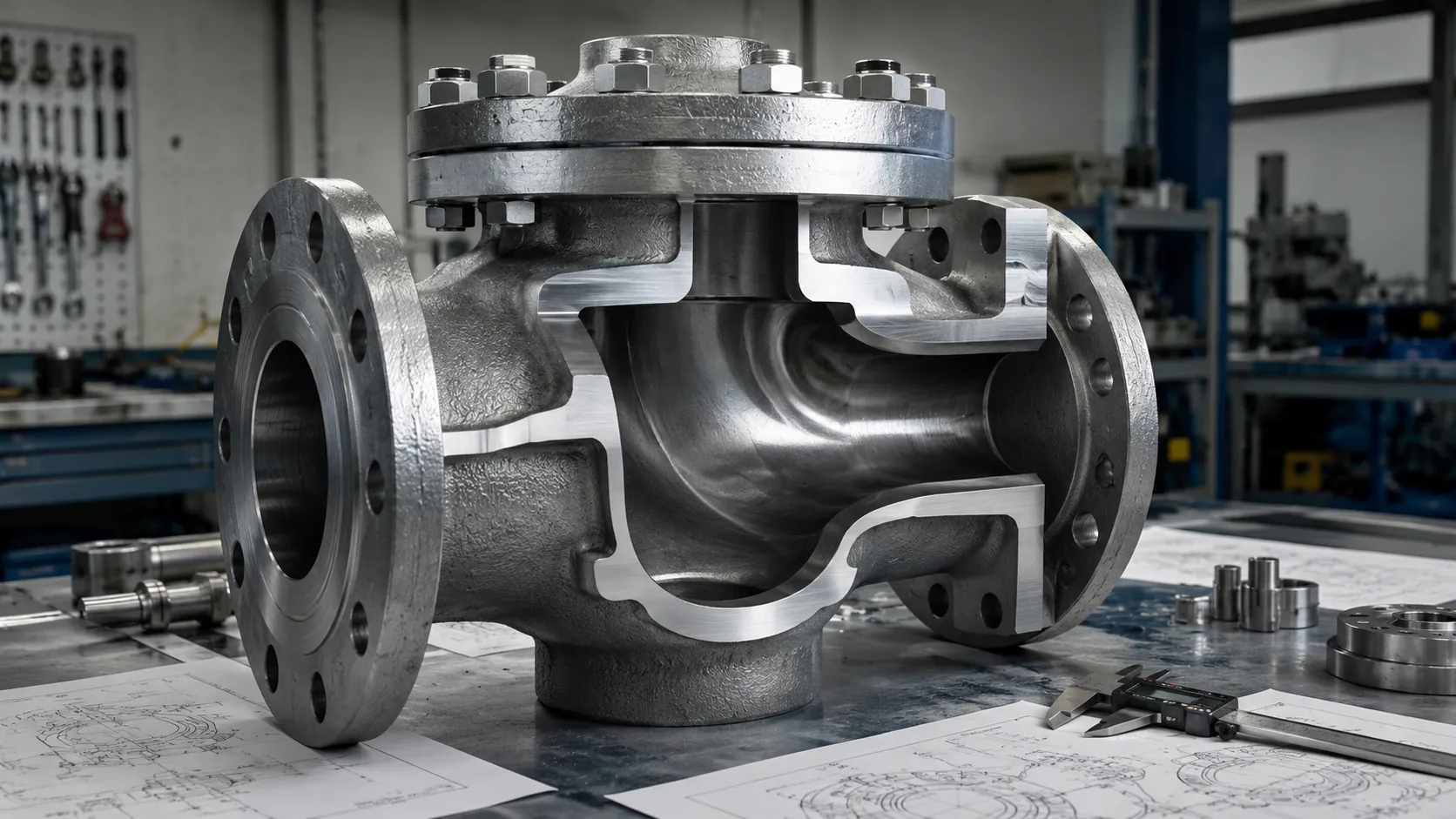
An industrial valve body is the main structural casing that forms the valve flow passage, connects the valve to the piping system, supports key internal components, and normally forms a major part of the pressure boundary. The body alone, however, does not determine service suitability. Buyers must also confirm the valve type, body construction, material specification, pressure-temperature rating, end connection, inspection scope, and complete project datasheet.
Understanding the valve body is more than learning the name of a component. It helps engineers and procurement teams compare quotations, identify specification gaps, and confirm whether suppliers are offering the same technical scope across an industrial valve product range. It also prevents a common procurement error: treating nominal size, pressure class, and a generic alloy description as proof that two valves are technically equivalent.
What Is an Industrial Valve Body?
The valve body is the primary casing through which the process medium flows. Depending on the valve design, it may contain or support the ball, gate, disc, plug, seat rings, cage, liner, shaft, or other operating components.
Its main functions generally include:
- forming the principal flow passage;
- connecting the valve to upstream and downstream piping;
- containing internal pressure as part of the pressure boundary;
- supporting and locating internal components;
- providing drains, vents, bypass connections, body cavities, or auxiliary ports where required;
- transferring certain piping, operating, and actuator loads through the valve structure.
The exact function and shape of the body depend on the valve family. A ball valve body does not have the same internal geometry as a globe, butterfly, gate, check, or control valve body.
The body is also not necessarily the entire pressure boundary. A complete pressure-retaining assembly may include a bonnet, cover, body joint, bolting, gasket, stem sealing system, or other components, depending on the design.
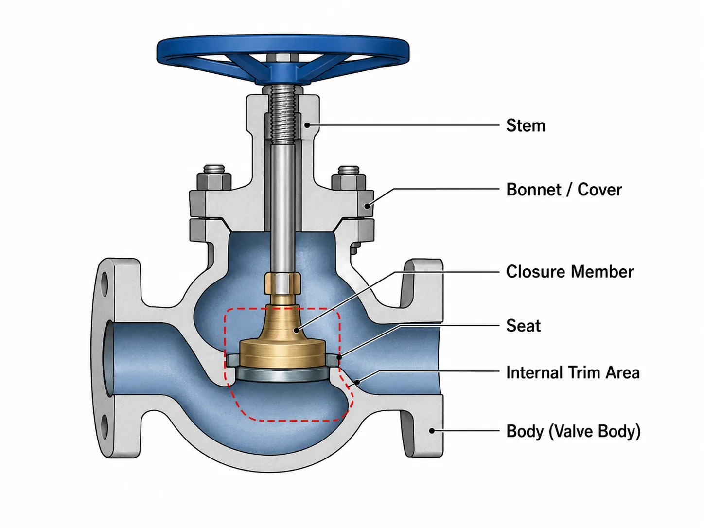
Valve Body vs Bonnet, Cover, and Trim
Several valve terms are frequently confused during specification and quotation review.
| Component | General function |
|---|---|
| Valve body | Main casing, flow passage, piping connection, and primary support for internal parts. |
| Bonnet or cover | Closes an opening in the body and may support the stem, packing, guide, or access arrangement. |
| Trim | Internal operating, guiding, or sealing components as defined by the applicable valve specification. |
| Seat | Provides the sealing interface between the body or seat ring and the closure member. |
| Stem or shaft | Transfers manual or actuated motion to the closure member. |
| Closure member | Ball, disc, gate, plug, piston, or another component that controls or stops flow. |
Not every valve has a traditional removable bonnet. Some butterfly valves, ball valves, wafer check valves, and welded-body designs use different access and assembly arrangements. Trim definitions can also vary by valve type, standard, and purchase specification, so the quotation should state exactly which components are included.
Why Does Valve Body Design Matter?
Valve body design affects pressure containment, piping compatibility, flow geometry, maintenance access, manufacturing method, and inspection requirements. It should be reviewed as part of the complete valve design rather than as an isolated component.
Pressure Boundary
The body must be suitable for the specified pressure and temperature within the applicable design framework. A pressure class or PN designation by itself is not enough. The buyer must also review the body material, design temperature, valve type, applicable standard, connection type, and manufacturer-confirmed rating.
For valves within its scope, ASME B16.34-2025 addresses pressure-temperature ratings, materials, dimensions, tolerances, nondestructive examination, testing, and marking. The standard applies to defined categories of new valve construction; it does not remove the need to identify the applicable product standard, project specification, design conditions, or valve-specific manufacturer rating.
A Class 300 or PN 40 marking is therefore not a fixed allowable pressure for every material and temperature. The acceptable pressure-temperature basis changes with the material group, design standard, valve construction, end connection, and design temperature. Technical approval should record the actual design pressure and design temperature rather than relying only on the class designation.
Flow Passage
The body forms or contains the flow path, which may be straight-through, angle-pattern, offset, multiport, full-bore, reduced-bore, or otherwise shaped for the valve design. Geometry can affect pressure loss, capacity, turbulence, solids accumulation, erosion, and control behavior; product-specific flow or sizing data are needed where these effects matter.
Engineering example — connection size did not establish flow capacity: Two DN100 Class 300 valves can have the same flanged ends while using different internal bore diameters, seat-port areas, or flow paths. A reduced-port or highly offset design may produce materially different pressure loss from a full-bore design. The cause is the internal geometry, not the flange size. Prevent this mismatch by confirming bore designation, minimum flow area, Cv/Kv where applicable, and the allowable system pressure drop before award.
Piping Integration
The body determines how the valve connects to the piping system. Important details can include:
- end-connection type, standard, flange facing, gasket arrangement, or weld preparation;
- face-to-face or end-to-end dimension, flow direction, and installation orientation;
- piping, actuator, operating, and maintenance clearance;
- required drain, vent, bypass, injection, or auxiliary connections.
A valve may have the correct nominal size and pressure designation but still be unsuitable if its dimensional standard, flange facing, weld preparation, or face-to-face dimension does not match the piping specification.
Internal Component Support and Maintenance Access
Seats, guides, liners, shafts, cages, bearings, and closure members are located relative to the body. Machining accuracy, alignment, surface condition, and assembly tolerances may therefore affect sealing, operating torque, movement, wear, and repeatability. A body can meet its external connection dimensions yet still create leakage or high torque if the seat pockets, stem bore, body-joint faces, or guide locations are machined from inconsistent datums.
Body construction also determines how the valve can be disassembled. Split-body, three-piece, top-entry, bolted-cover, one-piece, and fully welded constructions support different maintenance strategies. No arrangement is automatically best; the decision depends on service criticality, leakage risk, piping layout, available space, and project maintenance philosophy.
Actual allowable external piping loads, bending moments, actuator reactions, and support conditions must be confirmed from the applicable valve design, project specification, installation analysis, and valve-specific manufacturer data; they should not be inferred from valve size or body appearance.
Valve Body Technical Review Matrix
Use this matrix to align the body design, service basis, inspection scope, and supplier evidence before technical approval.
| Review item | Confirm | Evidence | Main risk if omitted |
|---|---|---|---|
| Function and service | Valve duty, medium, solids, cycling, and differential conditions | Process and valve datasheets | The selected body pattern may not suit the duty. |
| Construction | Body assembly and cast, forged, fabricated, or welded route | Sectional drawing and material specification | Pressure joints and maintenance access may be misunderstood. |
| Material | Exact specification, grade, heat treatment, and traceability | MTC, heat number, and traceability records | Material identity cannot be demonstrated. |
| Rating | Pressure-temperature basis at design conditions | Applicable standard and manufacturer rating data | Class or PN may be used outside its confirmed basis. |
| Connections | End standard, facing or weld preparation, and dimensions | Piping class and approved GA drawing | The valve may not fit the line or installation space. |
| Inspection | NDT and PMI methods, extent, locations, and acceptance | ITP, procedures, and reports | Supplier inspection scopes may differ. |
| Testing | Shell, seat, functional, and project-specific tests | Test procedure, acceptance criteria, and reports | One test may be mistaken for another requirement. |
| Documents | Drawings, certificates, dossier, inclusions, and deviations | Document list and deviation schedule | Technical differences may emerge after award. |
Decision rule: Medium, pressure-temperature conditions, valve duty, end connection, installation loads, and inspection class can change the acceptable body construction. Matching size, class, and a generic material name do not establish technical equivalence.
How Are Industrial Valve Bodies Classified?
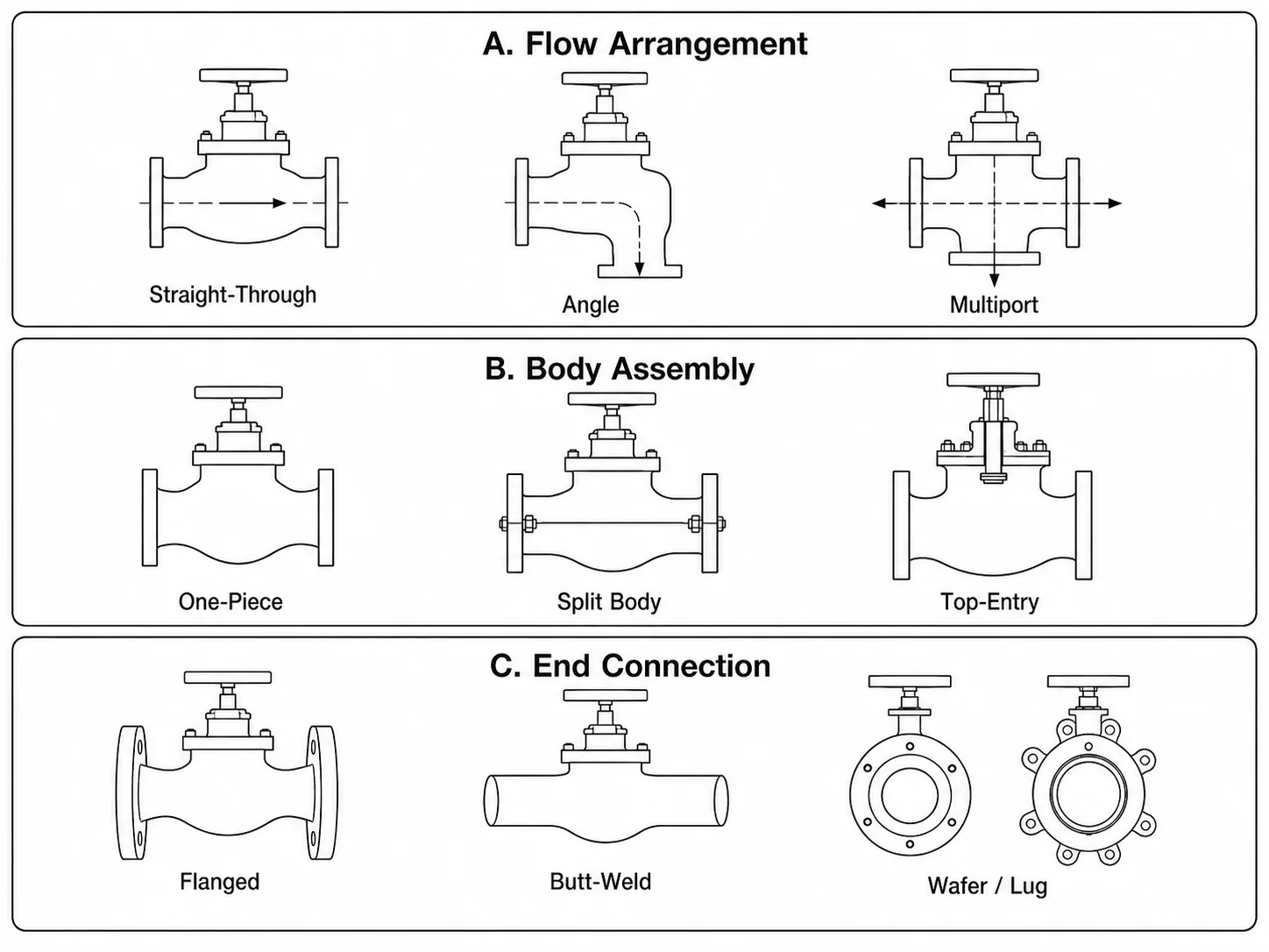
“Valve body type” can refer to several different design dimensions. Buyers should specify whether they mean flow arrangement, body assembly, manufacturing route, or end connection.
Classification by Flow Arrangement
- Straight-through: inlet and outlet are generally aligned.
- Angle-pattern: the flow direction changes through the body.
- Three-way or multiport: the body connects more than two flow paths.
- Offset or special path: the passage is arranged around the valve mechanism or application requirement.
Flow arrangement should not be confused with valve function. Isolation, throttling, non-return, mixing, diverting, and process control describe what the valve must do in the system.
Classification by Body Assembly
Depending on the valve family, body construction may be described as one-piece, two-piece, three-piece, split-body, side-entry, top-entry, bolted-cover, pressure-seal, fully welded, or fabricated.
These terms are not interchangeable across all valve types. The approved sectional drawing should confirm the actual pressure joints, assembly sequence, seat retention, stem arrangement, and maintenance access.
Classification by End Connection
Industrial valve bodies may use flanged, butt-weld, socket-weld, threaded, wafer, lug, clamp, or project-specific connections. The end connection must be evaluated with the piping material specification, dimensional standard, rating basis, flange facing, bolting, welding procedure, and installation requirements.
Cast vs Forged Valve Bodies
Cast and forged bodies are both widely used in industrial valve construction. The appropriate manufacturing route depends on valve design, size, material, geometry, pressure-temperature conditions, inspection requirements, manufacturing availability, and the project specification.
Cast Valve Bodies
A cast body is formed from molten metal in a mold and then heat treated, cleaned, machined, inspected, and tested as required. Casting can support complex passages, larger geometries, integrated flanges, bosses, and ribs.
Surface appearance alone cannot establish casting quality. Typical casting discontinuities include shrinkage cavities, shrinkage porosity, gas porosity, inclusions, cold shuts, hot tears, and surface-connected cracking. Their significance depends on location, size, orientation, stress level, remaining wall thickness, and the acceptance criteria invoked by the purchase specification. The RFQ should define the exact material, heat treatment, permitted repair route, traceability, and required examination within the project ITP.
Repair welding, where permitted, should not be treated as an informal cosmetic correction. The purchaser may need an approved repair procedure, welder qualification, excavation and re-examination records, compatible filler metal, post-weld heat treatment where required, and final NDE. The applicable material specification, project requirements, and approved quality plan determine whether repair is acceptable.
For a more detailed overview of mold preparation, pouring, heat treatment, machining, inspection, and related manufacturing controls, see the valve body casting process.
Forged Valve Bodies
A forged body starts with mechanically worked billet or bar before final machining and assembly. It is common in compact, small-bore, high-pressure, and other project-specific designs. Mechanical working can refine and orient the grain flow, but the benefit depends on starting-stock quality, forging reduction, temperature control, heat treatment, and the relationship between grain flow and the finished geometry.
“Forged” is not a complete specification. Buyers must still confirm the exact material, heat treatment, geometry, rating, NDT, traceability, and final test scope. Forgings can also contain laps, seams, bursts, inclusions, hydrogen-related discontinuities, or heat-treatment problems; machining a body from generic bar stock is not automatically equivalent to a qualified forging route. See the general valve forging process overview for additional manufacturing context.
Neither Manufacturing Route Is Universally Superior
| Review factor | Cast body | Forged body | Buyer check |
|---|---|---|---|
| Geometry | Can accommodate complex and larger shapes. | Often used for compact or heavily machined forms. | Review the exact design drawing. |
| Size availability | Available across many sizes and geometries, subject to foundry and pattern capability. | Available where suitable forging stock and machining capacity exist. | Confirm the exact supplier range and approved design. |
| Material document | Casting specification required. | Forging specification required. | Compare exact specifications, not generic alloy names. |
| Typical discontinuities | Shrinkage, porosity, inclusions, hot tears, cold shuts, and surface cracking may require process control and targeted examination. | Laps, seams, bursts, inclusions, internal discontinuities, and heat-treatment issues remain possible. | Do not assume either route is defect-free; match the examination method to the risk and geometry. |
| Inspection | Casting-related RT, UT, MT, or PT may be specified by critical area and acceptance level. | Forging-related UT, MT, or PT may be specified according to stock form and finished geometry. | Define method, extent, location, stage, procedure, personnel qualification, and acceptance criteria. |
| Cost and lead time | Depends on pattern, alloy, quantity, inspection, machining, and supplier capacity. | Depends on forging stock, alloy, machining, inspection, and supplier capacity. | Compare the normalized technical scope rather than manufacturing route alone. |
| Service suitability | Depends on the complete valve design. | Depends on the complete valve design. | Follow project data and applicable specifications. |
How Should Valve Body Material Be Reviewed?
Body material selection starts with the service conditions, not with a preferred alloy name.
For a broader review of service conditions, damage mechanisms, and material specifications, use the valve body material selection guide.
Confirm the Process Medium
The review should consider chemical composition, concentration, gas or liquid phase, suspended solids, contaminants, cleaning media, external atmosphere, and credible upset conditions. A material that performs acceptably in one concentration or temperature range may behave differently under another.
Review Pressure and Temperature Together
The material grade, valve design, pressure designation, and design temperature must be assessed together. Pressure class alone does not establish the allowable operating pressure at every temperature.
Evaluate Relevant Damage Mechanisms
Depending on the service, the body review may need to consider general corrosion, localized corrosion, stress-corrosion cracking, erosion, corrosion-erosion interaction, low-temperature toughness, elevated-temperature strength, thermal cycling, external corrosion, weldability, and heat-treatment requirements.
Separate Body, Trim, and Sealing Materials
The body material does not define the complete material configuration. Buyers should separately confirm the body, bonnet or cover, closure member, stem or shaft, seat, packing, gasket, bolting, bearings, hardfacing, overlay, lining, and coating.
Typical Valve Body Material Families and Buyer Checks
The following examples are material-specification families, not automatic recommendations. Final selection depends on the design code, pressure-temperature rating, medium, concentration, contaminants, minimum design metal temperature, fabrication route, corrosion mechanisms, and project specification.
| Material family | Typical body examples | Engineering use direction | Buyer checks |
|---|---|---|---|
| Cast carbon steel | ASTM A216 WCB or WCC | Common pressure-containing castings where the material and rating suit the temperature and medium. | Confirm design temperature, corrosion allowance, weld-repair controls, heat treatment where applicable, and whether low-temperature impact requirements apply. |
| Cast low-temperature steel | ASTM A352 LCB or LCC | Pressure-containing castings intended primarily for low-temperature service. | Confirm minimum design metal temperature, impact-test temperature, heat treatment, section thickness, and certificate traceability. |
| Cast Cr-Mo alloy steel | ASTM A217 WC6 or WC9 | Elevated-temperature or project-specific alloy service where the complete design basis supports the grade. | Confirm heat treatment, welding and repair procedure, hardness or other project limits, and the applicable pressure-temperature rating. |
| Cast austenitic stainless steel | ASTM A351 CF8M or CF3M | Corrosion-resistant service where the exact chemistry, temperature, and damage mechanisms are compatible. | Confirm solution heat treatment, grade suffix, chloride and acid conditions, intergranular-corrosion concerns, and matching trim and bolting. |
| Cast duplex stainless steel | ASTM A995 Grade 4A or 5A | Service requiring a combination of strength and corrosion resistance when composition and heat treatment are properly controlled. | Confirm solution annealing and rapid cooling, phase balance or ferrite requirements if specified, PMI, corrosion testing where required, and repair controls. |
| Forged carbon, low-temperature, stainless, or duplex steel | Examples include ASTM A105, A350 LF2, and relevant ASTM A182 grades | Compact and machined body constructions where the selected forging grade matches the service and design standard. | Confirm the exact grade, class or condition, forging route, heat treatment, NDE, traceability, and finished-body pressure-temperature basis. |
Engineering example — low-temperature material mismatch: A supplier may quote an ASTM A216 WCB body because the nominal size and pressure class match the datasheet. The problem arises when the line’s minimum design metal temperature and impact-toughness requirement were never transmitted. The prevention is to state the minimum design temperature, impact-test basis, exact material specification, heat treatment, and documentation requirement before quotation; a low-temperature grade such as an applicable ASTM A352 material should only be selected after the complete design basis is confirmed.
Engineering example — body alloy selected but the valve still failed early: A corrosion-resistant body can remain intact while an incompatible stem, seat ring, bolting material, gasket, or soft seal degrades. The cause is a material review limited to the body casting. Prevent this by issuing a complete wetted-parts and pressure-retaining-parts material schedule and checking temperature, concentration, chlorides, H2S, solids, velocity, and cleaning media for every critical component.
What Inspection and Documents Verify a Valve Body?
The inspection scope should be defined before purchase. Adding extensive examination after manufacturing can increase cost, delay delivery, or make some verification impossible.
Material Traceability
Typical evidence includes the MTC, exact specification and grade, heat number, required heat-treatment record, traceability-transfer records, markings, and PMI where specified.
PMI can support elemental-composition screening at the tested location, but it does not establish all mechanical properties, heat treatment, microstructure, impact toughness, phase balance, or service suitability. The MTC and PMI therefore answer different questions: the MTC reports heat-level material results and condition, while PMI helps verify that the tested finished component is chemically consistent with the intended alloy family.
Engineering example — certificate correct, finished body wrong: An MTC may identify the intended stainless or alloy grade while PMI on the machined body detects a different alloy. The usual cause is broken heat-number traceability during cutting, heat treatment, subcontract machining, or part transfer. Prevent this with controlled material segregation, heat-number transfer records, durable part marking, and project-defined PMI at an appropriate manufacturing stage.
Wall Thickness and Machining Control
Pressure-boundary adequacy depends on the finished geometry, not only the as-cast or as-forged blank. Machining allowance, casting tolerance, local blend-out, repair excavation, and corrosion allowance can reduce the remaining wall. The drawing and inspection plan should identify minimum finished wall thickness, critical local sections, measurement method, and acceptance basis where these controls are required.
Machining inspection should also cover body-joint faces, flange facing, weld-end preparation, seat pockets, stem or shaft bores, guide locations, concentricity, perpendicularity, and datum control as applicable. See the Raymon Valve resource on valve wall-thickness testing for related inspection context.
Visual, Dimensional, and Nondestructive Examination
Inspection may cover surface condition, machining, wall or local dimensions where specified, end connections, face-to-face dimensions, markings, and alignment.
Radiographic, ultrasonic, magnetic-particle, and liquid-penetrant examinations detect different discontinuity types. The RFQ should define the method, area, extent, manufacturing stage, procedure, personnel qualification, and acceptance criteria. A generic instruction such as “100% NDT” is incomplete because it does not identify the method, examination volume, critical zones, or acceptance level.
| Method | Best suited to | Important limitation | RFQ clarification |
|---|---|---|---|
| VT | Surface condition, workmanship, visible cracks, fins, laps, arc strikes, and machining condition. | Cannot establish internal soundness. | Define surface standard, lighting, access, stage, and acceptance criteria. |
| PT | Surface-breaking discontinuities in nonporous materials, including many nonmagnetic alloys. | Does not reveal discontinuities that are not open to the examined surface. | Define penetrant system, surface preparation, dwell, area, and acceptance. |
| MT | Surface and near-surface discontinuities in ferromagnetic materials. | Not applicable to austenitic stainless steel and other nonferromagnetic materials. | Define magnetization technique, field direction, coverage, and acceptance. |
| RT | Volumetric examination and imaging of many internal casting discontinuities. | Sensitivity depends on geometry, thickness, orientation, technique, and image quality. | Define critical zones, views, quality level, acceptance standard, and repair re-examination. |
| UT | Internal discontinuity detection and thickness evaluation where geometry and material permit. | Complex body geometry, coarse cast structure, surface condition, and reference calibration can limit interpretation. | Define technique, calibration, examination volume, reporting threshold, and acceptance. |
For a broader overview of inspection activities, see valve inspection and testing.
Engineering example — shell test passed but machining exposed shrinkage: A cast body can hold the hydrostatic test pressure and later reveal shrinkage or porosity when the seat pocket or body joint is machined. The test confirmed pressure-boundary performance under the stated procedure; it did not map every internal discontinuity. Prevent this by identifying heavy sections and high-stress zones during drawing review, applying appropriate RT or UT where justified, and repeating visual or surface examination after defect excavation or critical machining.
Shell Pressure Testing
A shell test evaluates pressure-boundary integrity under the specified procedure. It is separate from seat-leakage and functional testing.
ISO 5208:2015 addresses pressure testing of metallic industrial valves and is intended for use with the relevant product standard. API Standard 598 is another commonly specified valve inspection and testing reference for valve types within its scope. The RFQ and ITP should state which product and test standards apply, including any project-specific leakage acceptance, test medium, duration, witness, and documentation requirements. See Raymon Valve’s general resource on valve pressure testing.
A successful shell test does not by itself prove corrosion compatibility, seat tightness, fire-safe or fugitive-emission performance, fatigue life, or suitability for every operating condition.
What Each Supplier Document Can and Cannot Prove
Procurement teams should avoid treating one document or test as a substitute for the complete evidence package. Each item answers a different technical question.
| Evidence item | What it can support | What it does not prove by itself |
|---|---|---|
| Approved datasheet and sectional drawing | Quoted construction, pressure joints, component arrangement, materials, dimensions, and specified options. | That the manufactured valve matches the drawing without inspection and traceability records. |
| Material test certificate (MTC) | Reported heat identity, material specification, chemical analysis, mechanical results, and heat treatment where recorded. | That the certificate belongs to the finished body unless traceability is maintained through production. |
| Positive material identification (PMI) | Elemental composition screening for the tested location within the method’s capability. | Complete mechanical properties, microstructure, heat treatment, grade condition, or corrosion suitability. |
| Nondestructive examination report | Results for the stated method, examined area, manufacturing stage, procedure, and acceptance criteria. | Absence of every possible discontinuity or suitability outside the examined scope. |
| Repair-welding dossier, when applicable | Approved procedure, welder qualification, defect excavation, filler material, heat treatment, and re-examination records. | That repair was permitted by every applicable material, design, and project requirement unless the approval basis is documented. |
| Shell pressure-test report | Pressure-boundary performance under the stated test pressure, medium, duration, and acceptance procedure. | Seat leakage class, fire-safe performance, fugitive-emission performance, fatigue life, or material compatibility. |
| Inspection and test plan (ITP) | Planned manufacturing, inspection, review, hold, and witness points. | That each activity was completed unless signed records and final reports are provided. |
| Final document dossier | Consolidated evidence for the supplied valve, subject to document completeness and cross-reference accuracy. | Technical conformity if drawings, markings, certificates, and reports are inconsistent. |
Inspection and Test Plan
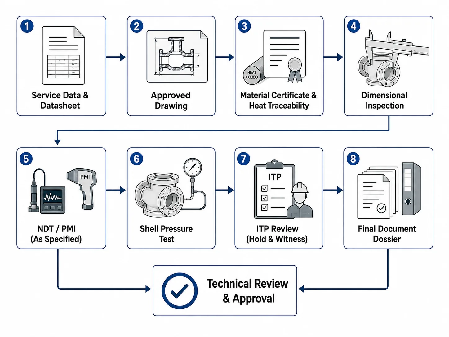
For project valves, the ITP may identify document review, material verification, dimensional inspection, NDT review, assembly inspection, shell and seat testing, functional testing, coating inspection, third-party hold or witness points, final document review, and release authorization.
Common Valve Body Specification Mistakes
Common procurement errors include:
- selecting by size and class without checking design temperature and service data;
- using a generic material name instead of an exact specification and grade;
- assuming forged construction is automatically superior to casting;
- treating a shell test as proof of seat, emission, fire, or material performance;
- omitting connection dimensions, finished minimum wall thickness, NDT scope, traceability, or document requirements;
- specifying “100% NDT” without a method, area, stage, procedure, or acceptance criteria;
- accepting an MTC without verifying that heat-number traceability reaches the finished body;
- allowing weld repair without an approved procedure, re-examination, and repair record;
- comparing prices before aligning inclusions, exclusions, and technical deviations.
Valve Body RFQ Checklist
The datasheet, approved drawing, quotation, and deviation schedule should state the same body construction, dimensions, materials, service basis, inspection scope, and document requirements.
Include the following information where relevant:
- valve function, medium, composition, phase, solids, and operating frequency;
- normal and design pressure and temperature, plus differential conditions where relevant;
- nominal size, class or PN, end connection, dimensional standard, orientation, and clearance;
- body assembly and cast, forged, fabricated, or welded manufacturing route;
- body, bonnet or cover, trim, seat, packing, gasket, bolting, lining, and overlay materials;
- corrosion, erosion, fouling, cleaning, external environment, and special-service conditions;
- applicable design, product, connection, and project specifications;
- minimum finished wall thickness, corrosion allowance, machining datums, and critical dimensional tolerances where required;
- NDT and PMI method, extent, location, manufacturing stage, procedure, personnel qualification, and acceptance criteria;
- repair-welding permission, approval route, re-examination, and documentation requirements;
- shell, seat, functional, low-temperature, emission, fire, or other required tests where applicable;
- MTC, heat traceability, heat-treatment records, ITP, inspection reports, and third-party hold or witness points;
- drawings, procedures, inspection reports, final dossier, marking, preservation, and packing;
- base-price inclusions, optional items, exclusions, and a clause-by-clause deviation list.
Before comparing price and delivery, ask every supplier to confirm the same technical basis. Otherwise, the quotations may represent different materials, body constructions, inspection scopes, tests, and document packages.
Normalize Supplier Quotations Before Comparing Price
A technically lower-priced quotation may simply exclude inspection, documentation, material controls, or dimensional requirements included by another supplier. Use a common comparison schedule before commercial evaluation.
| Comparison line | Required supplier response | Why it matters |
|---|---|---|
| Body design | State the assembly construction, manufacturing route, and approved drawing. | Maintenance access, pressure joints, and inspection needs may differ. |
| Materials | State full specifications for pressure-retaining, wetted, sealing, and bolting components. | Generic alloy names do not establish equivalent scope. |
| Rating and connections | Confirm the pressure-temperature basis, end standard, dimensions, and installation orientation. | The same class or PN does not guarantee piping compatibility or service suitability. |
| Inspection and testing | List NDT, PMI, shell, seat, functional, and special tests with extent and reports. | Inspection and testing can materially change cost and lead time. |
| Documents | List drawings, MTCs, ITP, procedures, reports, approvals, and dossier format. | Omissions often surface after order placement. |
| Deviations and exclusions | Separate base scope, options, exclusions, third-party costs, and clause-by-clause deviations. | Commercial totals are not comparable until the technical scope is aligned. |
Illustrative example: Two DN100 Class 300 carbon-steel offers are not technically equivalent if one includes specified NDT, heat traceability, an approved ITP, dimensional reporting, and a complete test dossier while the other lists only a generic body material and shell test. Align exclusions and evidence before comparing price. This is a procurement example, not a customer project or performance claim.
Technical References and Scope
The following official sources support the general rating and testing context used in this article. They do not prove conformity of a specific valve or manufacturer.
| Reference | Used for in this article | Does not prove by itself |
|---|---|---|
| ASME B16.34-2025 | Pressure-temperature ratings, materials, dimensions, tolerances, NDE, testing, and marking context for valves within its scope. | That a specific Raymon Valve model or project valve conforms without approved design and product documentation. |
| ISO 5208:2015 | Pressure-boundary integrity, closure tightness, and closure-mechanism test context for metallic industrial valves when used with the applicable product standard. | Material compatibility, complete design suitability, fire-safe performance, fugitive-emission performance, or service life. |
| API Standard 598 listing | Official API identification of API 598 as the valve inspection and testing standard within the API valve standards program. | Which edition, leakage acceptance, or project supplements apply to a specific purchase order. |
| ASTM A216/A216M | Carbon-steel castings for valves and other pressure-containing parts within the specification scope. | Suitability for low-temperature, corrosive, or other service without the complete design and material review. |
| ASTM A352/A352M | Ferritic and martensitic steel castings intended primarily for low-temperature pressure-containing service. | That a quoted grade meets the project MDMT, impact, heat-treatment, or section-thickness requirements without records. |
| ASTM A351/A351M | Austenitic steel castings for valves and other pressure-containing parts. | Corrosion resistance in a specific medium or compatibility of trim, bolting, gaskets, and seals. |
| ASTM A995/A995M | Austenitic-ferritic duplex stainless-steel castings for pressure-containing parts. | Correct phase balance, corrosion performance, repair quality, or project conformity without heat-treatment and inspection evidence. |
Final Selection Requires a Complete Valve Datasheet
The valve body is the central structural casing of an industrial valve, but it is only one part of the complete selection. Body construction, finished wall thickness, material and heat treatment, pressure-temperature rating, flow passage, end connection, body joint, trim, sealing system, manufacturing route, repair controls, inspection, testing, and project documentation must be reviewed together.
A technically comparable quotation should clearly identify what is supplied, which requirements are included, which standards apply, and where the supplier proposes deviations. Additional valve engineering articles are available in the Raymon Valve Knowledge Center.
Request Valve Body and Material Review
Send the available project data, supplier quotation, and technical deviation list so the proposed body construction, material scope, inspection requirements, and document package can be reviewed on a common basis.
- valve type and required function;
- medium, design pressure, and design temperature;
- nominal size, class or PN, and end connection;
- body, trim, seat, packing, and gasket requirements;
- corrosion, erosion, solids, or special-service conditions;
- finished wall-thickness, dimensional, NDT, PMI, testing, ITP, repair-control, and final document requirements;
- supplier quotation, inclusions, exclusions, and technical deviations.
In the contact message, identify the datasheet, supplier quotation, and technical deviation list available for review. Document transfer can be arranged after the initial contact if the form does not accept attachments.
Request a Project-Specific ReviewFrequently Asked Questions
What is the main function of a valve body?
The valve body forms the main casing and flow passage, connects the valve to the piping system, supports internal components, and normally forms a major part of the pressure boundary. Its exact role depends on the valve type and construction.
Is the valve body the same as the bonnet?
No. The body is the main casing, while a bonnet or cover normally closes an access opening and may support the stem, packing, or internal guides. Some valve designs do not use a traditional separate bonnet.
Is a forged valve body always better than a cast body?
No. Cast and forged bodies can both be suitable when properly designed, manufactured, inspected, and applied. The decision depends on size, geometry, material, pressure-temperature conditions, service risk, inspection requirements, and project specification.
Does pressure class confirm that the valve body is suitable?
No. Pressure class or PN is only one part of the review. Design temperature, material group, valve design, end connection, applicable standard, medium, and manufacturer rating must also be confirmed.
What documents should verify a valve body?
Depending on the project, documents may include the datasheet, approved sectional drawing, material certificate, heat-traceability record, heat-treatment record, dimensional report, NDE and PMI reports, repair-welding dossier where applicable, pressure-test report, signed ITP, and final document dossier.
Can a cast valve body be used for high-pressure service?
Yes, a cast body can be used in high-pressure service when the complete valve design, material, pressure-temperature rating, wall thickness, casting process, heat treatment, NDE, testing, and applicable product standard support the duty. “Cast” or “forged” alone is not a valid pressure-service classification.
What is the difference between an MTC and PMI?
An MTC reports material results and identification associated with a heat or production lot, while PMI checks elemental composition at the tested component location. PMI helps detect alloy mix-ups but does not prove heat treatment, mechanical properties, impact toughness, microstructure, or complete service suitability.
Which NDE method should be specified for a valve body?
The method must match the material, geometry, discontinuity risk, and project requirement. PT or MT is commonly used for surface or near-surface discontinuities, while RT or UT may be selected for internal examination. The RFQ should define the method, critical areas, extent, manufacturing stage, procedure, qualification, and acceptance criteria.
What information should be included in a valve body RFQ?
Include valve type and duty, medium, design pressure and temperature, minimum design metal temperature where relevant, size and rating, end connection, body construction, exact material grade, corrosion allowance, minimum wall or dimensional requirements, NDE and PMI scope, repair controls, test standards, quantity, drawings, ITP, traceability, and final document requirements.
Engineering note: This article supports preliminary technical screening, supplier evidence review, and RFQ normalization. It does not replace project-specific sizing, material compatibility review, pressure-boundary design verification, applicable-code assessment, or responsible-engineer approval. Final selection should be confirmed against the complete process data, project specification, approved drawings, applicable rating basis, and valve-specific manufacturer documentation.
Prepared as organizational technical content by Raymon Valve. Learn more on the About Raymon Valve page; no individual engineer credential or personal review claim is made.
 English
  German
  Arabic
  French
  Spanish
  Italian
  Portuguese
  Russian