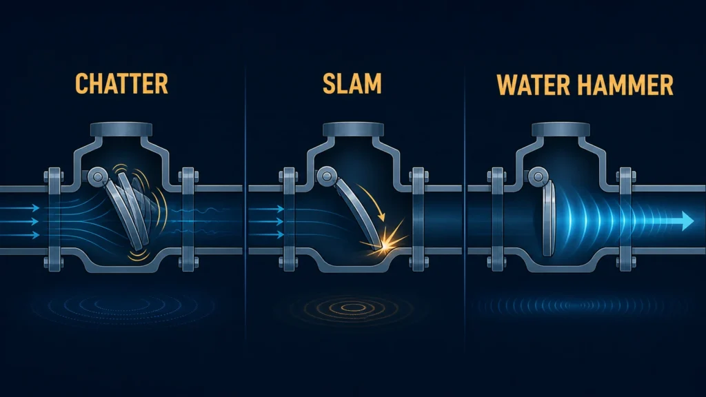
Engineering concept separating repeated check valve chatter, a closing slam event and a traveling system pressure wave

Vibrazioni della valvola di ritegno (Chatter) vs Battito (Slamming): Cause, prove sul campo e direzioni correttive

Check valve chatter and slamming are different events. Chatter is repeated unstable movement of the disc, plates, or poppet during an operating period; slam is a closing impact, commonly associated with rapid flow deceleration or reversal. Water hammer is the system pressure wave and should not be diagnosed from sound alone. Use event timing, flow and pressure history, pump or compressor status, piping layout, valve identity, motion evidence, and internal inspection before selecting a corrective action.

Replacing the valve, reducing its size, changing a spring, or selecting a product marketed as “non-slam” can change steady-state loss and dynamic behavior. Any correction needs evidence for the exact valve and system duty.

Limite di sicurezza: Follow the facility’s approved isolation, depressurization, lockout/tagout, inspection, and operating procedures. Do not approach, open, adjust, or bypass pressurized equipment based on this article. The responsible site authority must determine whether operation can continue and what diagnostic work is permitted.

Featured illustration: Concept distinction between repeated check-valve chatter, a closing slam event, and a traveling system pressure wave. It is not product, field-test, or project evidence.

Check Valve Chatter, Slam, and Water Hammer Are Not Synonyms

Chatter or Flutter

Chatter is repeated, unstable movement of the closure member. A disc, plate, or poppet may move between positions instead of remaining stably open or fully closed. The event may sound like clicking, rattling, or rapid impacts, but acoustic character alone is not enough to identify the motion.

Possible contributors include insufficient stable-opening force, pulsating or disturbed flow, changing differential pressure, friction, wear, deposits, damaged guides or hinges, loose stops, and spring behavior. “Oversized valve” is a hypothesis, not a universal diagnosis; compare the operating points with exact-model opening behavior and the project inputs described in the check valve sizing and stable-opening guide.

Slam

Slam is a closing impact that may occur while flow decelerates or reverses and the closure member is still traveling. Travel, moving mass, spring or gravity forces, friction, deceleration, and reverse velocity at closure all matter.

A valve described as spring-assisted, axial, silent, or non-slam does not automatically have an acceptable response in every system. The name identifies a construction direction or commercial category; it does not establish the actual closing event under a stated pump trip or compressor shutdown.

Water Hammer or Surge

Water hammer is a system pressure-wave response to changing fluid velocity. The check valve may initiate or amplify the change, respond to a transient generated elsewhere, or merely be near the loudest observation point.

La Hydraulic Institute’s waterhammer resources treat surge as a pumping and piping-system problem. Observe the valve and reconstruct the wider event.
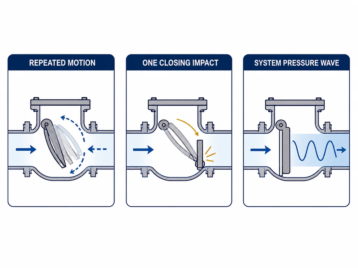
Three-panel diagram comparing repeated valve motion, one closing impact and a system pressure wave
Engineering schematic. Sound alone cannot identify which event occurred or where the transient began.

Quick Diagnostic Table: What Happened and When?

Observation Initial interpretation Evidenza richiesta Do not conclude yet
Repeated clicking during low or varying flow Possible unstable closure-member position Flow trend, differential pressure, synchronized vibration or motion evidence, exact-model opening data The valve is oversized without model and duty evidence
One impact after pump trip Possible delayed closure with reverse-flow exposure Trip timeline, pump coast-down, pressure trace, valve closing or reverse-velocity basis The check valve alone caused the pressure wave
Pipe movement or a pressure spike away from the valve A system transient may dominate Synchronized pressure, flow, pump and valve events plus the line profile The noise location is the surge origin
New noise after maintenance or a process change Assembly, wear, setup, support, or operating-point changes may matter Change record, inspection, settings, and before/after trends A different valve family is automatically required
Leakage after repeated impacts Seat or internal damage may exist Safely isolated inspection and the specified leakage test The leakage test identifies the original dynamic cause

This table establishes what to investigate; it does not authorize a corrective change.

Build the Event Timeline Before Naming the Cause

Ask what happened immediately before, during, and after the event—not only what it sounded like.

Separate the applicable operating states:

  • minimum continuous or intermittent flow;
  • normal operating flow;
  • maximum flow;
  • startup and ramp-up;
  • throttling or minimum-flow bypass changes;
  • pump or compressor shutdown and trip;
  • parallel-unit start or stop;
  • pulsating, cycling, or two-phase operation.

For each state, align available records on one time base:

  1. pump or compressor command, speed, and coast-down;
  2. upstream and downstream pressure;
  3. measured flow or a documented operating-point estimate;
  4. control-valve, bypass, or recirculation position;
  5. vibration or acoustic evidence with timestamps;
  6. check-valve motion evidence where it can be obtained safely;
  7. pipe, support, or connected-equipment response.

Use five columns: before, trigger, valve response, pressure/system response, e recovery. A pressure event that begins before the suspected impact, or noise that continues during steady low flow, changes the diagnostic direction.

Diagnostic Readiness Gate: Is There Enough Evidence to Act?

Use four status labels during the review: Confirmed means the value and its controlled source are recorded; Partial means some usable evidence exists but the decision boundary remains incomplete; Open means the decision cannot rely on that field; Not Applicable requires a recorded reason. A critical field marked Open is a hold point, not permission to fill the gap from a valve-family description.

Decision gate Minimum evidence Primary review owner If the gate remains Open
Event classification Synchronized equipment command, operating state, flow or defensible operating point, pressure response, and vibration/acoustic or motion evidence Operations and reliability Keep chatter, slam, and system surge as separate hypotheses
Condizioni operative Minimum, normal, maximum, startup, shutdown, trip, cycling, and parallel-unit cases where applicable Process, rotating-equipment, and system engineering Do not approve a size, spring, or control-sequence change
Exact valve identity Manufacturer, model, size, class/PN, ends, construction, flow direction, controlled drawing, IOM, and approved orientation Valve supplier and project engineering Do not transfer generic family behavior to the installed valve
Consequence and acceptance basis Project pressure limits, required closure function, permitted leakage, operational consequence, and defined acceptance criteria Responsible project or site engineer Escalate the analysis scope before implementing a dynamic correction
Evidence quality Instrument range, sample rate, time synchronization, sensor location, uncertainty, inspection condition, and document revision Instrumentation, reliability, and quality Qualify the uncertainty; do not treat an apparent event order as proven

Record the status, source document or data file, revision, reviewer, and date for each gate. This makes the diagnostic decision auditable and prevents a later proposal from being accepted against different assumptions.
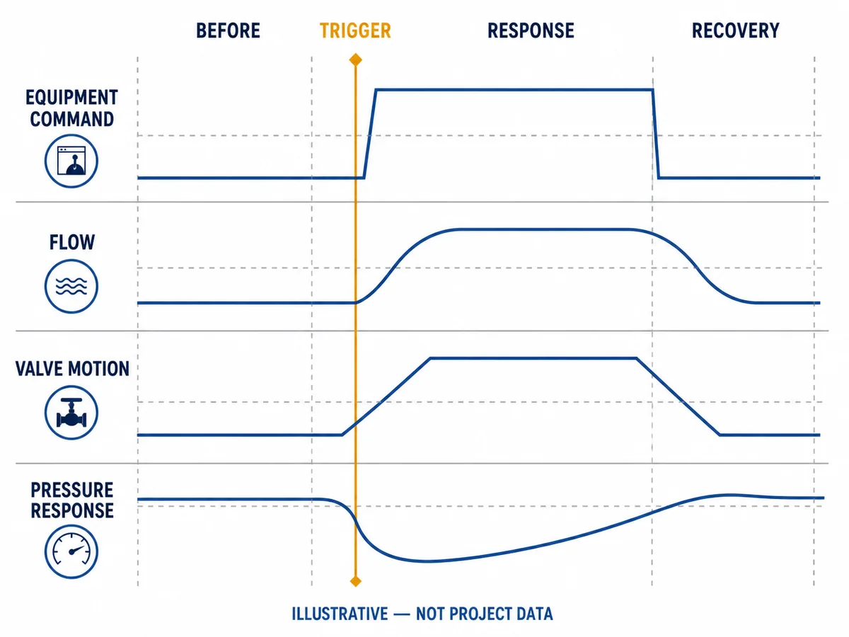
Example synchronized timeline for equipment command, flow, check valve motion and pressure response
Example diagnostic timeline, not measured project data. Event order must be reconstructed from the actual system records.

Why Check Valves Chatter

Insufficient Stable-Opening Margin

A check valve opens according to fluid forces, spring or gravity force, moving-element weight, friction, and geometry. At low or fluctuating flow, the closure member may not remain stable.

Fully-open Cv or Kv does not prove stable operation. The check valve sizing and stable-opening guide explains why line size and pressure class are insufficient. Request the exact model’s opening-position or stable-flow basis and its conditions.

Disturbed, Pulsating, or Multiphase Flow

Elbows, reducers, branches, rotating equipment, control actions, gas fraction, or pulsation can create changing loads. Their influence depends on piping geometry and valve construction.

Do not apply a universal number of straight pipe diameters. Use the approved installation instructions for the exact model, verify the as-built piping, and review whether the operating disturbance matches the event timeline.

Valve Condition and Internal Friction

Wear or damage can change motion. Inspect the closure member, hinge/pin/guide, bushings, spring, stops, seat, deposits, foreign material, looseness, misalignment, and damaged surfaces.

A new noise after maintenance may indicate assembly, setting, or parts issues; gradual onset may point toward wear or changed duty. Neither proves the cause.

Orientation and Installation

Gravity, spring direction, orientation, piping strain, support, and local geometry can affect motion. Horizontal or vertical acceptability must come from the exact valve’s controlled drawing and IOM.

Why Check Valves Slam

Flow Deceleration and Reverse-Flow Exposure

If the system decelerates quickly and the valve has not seated before flow reverses, reverse flow can build and then be arrested at closure. Consider valve and system response together.

Reverse velocity is not fixed by valve family. A supplier curve or calculation is relevant only when its size, spring, travel, fluid basis, and deceleration conditions match the project duty.

Travel, Inertia, Force, and Friction

Travel, moving mass, spring force, friction, stops, guides, hinges, and seat geometry affect response. A spring may assist closure while also changing opening behavior and pressure loss, so family rankings can mislead.

Use the dual-plate versus axial-flow comparison or the swing versus lift check-valve comparison to screen construction differences. Final approval still requires exact-model data.

Pump and Piping-System Interaction

Pump trip, coast-down, static head, line profile, parallel pumps, non-return paths, and control events can change the transient. High-consequence service may require responsible hydraulic transient analysis.

A quieter valve does not prove pressure remains within the limit; an audible event does not quantify the excursion.

Matrice Prove sul Campo – Causa – Verifica

Symptom or condition Possible causes Evidence to collect Verification owner Hold point
Repeated motion at minimum flow Opening instability, pulsation, friction, wear Flow and differential-pressure trend, model opening data, vibration/motion evidence, inspection Operations, valve supplier, and project engineering No size or spring change without a complete review
Impact at shutdown Delayed closure, reverse velocity, interacting equipment Synchronized trip, pressure and flow record; line profile; model closing evidence Hydraulic/system engineer and supplier Do not close the transient question from noise alone
Noise after a piping change Disturbed flow, altered support, new operating point As-built layout, change record, vibration and flow comparison Piping and reliability teams No universal straight-run conclusion
Leakage after repeated events Seat/internal damage, debris, misalignment Isolated inspection and controlled leakage test Maintenance and quality Test result does not identify the initiating cause
Motion in vertical or special orientation Gravity, spring, guide, or installation interaction Approved orientation, drawing, IOM, and operating data Supplier and project engineering Orientation remains open without model approval
Event in pulsating service Cyclic differential pressure, compressor/pump interaction, spring response High-resolution operating timeline and pulsation data Rotating-equipment/system specialist Steady-flow data alone are insufficient
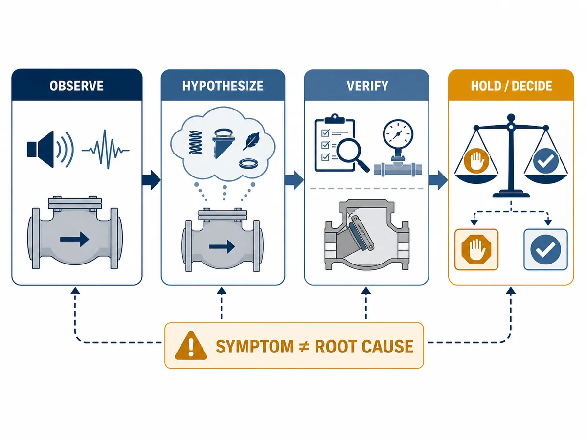
Field evidence workflow from observed check valve symptoms through hypothesis, verification and engineering decision
Example evidence workflow. A symptom identifies what to investigate; it does not prove the root cause.

Corrective Direction: Use a Hierarchy

1. Confirm the Symptom and Control Immediate Risk

Follow approved site procedures and let the responsible owner decide whether operation can continue. Preserve event records before changes. Do not perform live adjustment or intrusive inspection from an online guide.

2. Correct an Operating or Installation Cause When Evidenced

The review may identify operating, control, minimum-flow, pulsation, support, or installation issues. Any change requires the responsible technical approval; this article defines no safe setpoint.

3. Inspect and Restore the Existing Valve When Justified

After safe isolation, inspect the closure member, hinge/pin/guide, spring, stops, seat, clearances, deposits, damage, and assembly. Use controlled documents. A replaced part does not prove why damage began.

4. Re-select or Modify Only with Exact-Model Evidence

A different size, construction, spring, travel, damping, or installation may be considered. Each can alter loss, opening, closing, maintenance, and system interaction. Normalize evidence first.

5. Escalate to System Transient Analysis

Escalation is particularly relevant when the event involves significant pressure excursions, repeated trips, high static head, long lines, multiple pumps, hazardous media, or unacceptable consequences. The model should use controlled system inputs and be reviewed by the responsible engineering authority.

Normalize Corrective Options Before Approval

A corrective proposal should state the intended mechanism, the new risks it introduces, the evidence required before implementation, and the owner of acceptance. “Replace the valve” or “change the spring” is not a complete technical proposal.

Evaluation direction Intended question Rechecks required before approval Acceptance owner
Operating or control-sequence change Can the evidenced instability or reversal be reduced without changing the valve? Required production cases, minimum-flow route, control interactions, operating limits, and shutdown/trip response Process, controls, and system engineering
Inspect and restore the existing valve Is wear, damage, assembly, deposits, looseness, or friction responsible for the observed motion? Safely isolated inspection, controlled dimensions/clearances where specified, correct parts and assembly, functional or leakage test, and return-to-service criteria Maintenance, quality, supplier, and site authority
Evaluate a smaller nominal size Would a different opening margin better fit the required flow envelope? Pressure loss and capacity at every required case, connection/layout effects, velocity, stable-opening evidence, closing response, and transient consequence Process/hydraulic and project engineering
Evaluate a spring or internal configuration change Would different opening and closing forces address the verified mechanism? Cracking differential basis, opening position, pressure loss, travel, orientation, reverse-velocity/closing evidence, parts identity, and supplier approval Exact-model supplier and project engineering
Evaluate a different check-valve construction Does another exact model better fit the hydraulic, dynamic, installation, and maintenance requirements? Normalized curves, dynamic evidence, drawing, orientation, materials, tests, access, spares, deviations, and full system duty Project engineering and procurement
Evaluate system transient mitigation Is the unacceptable consequence controlled mainly at system level? Pump coast-down, controls, bypass or minimum-flow paths, surge devices where proposed, line profile, failure cases, safeguards, and approved transient study Hydraulic transient specialist and responsible engineer

The chosen direction should close the verified cause and meet predefined acceptance criteria. It should not be selected only because the noise changes or because a marketed valve name appears to match the symptom.
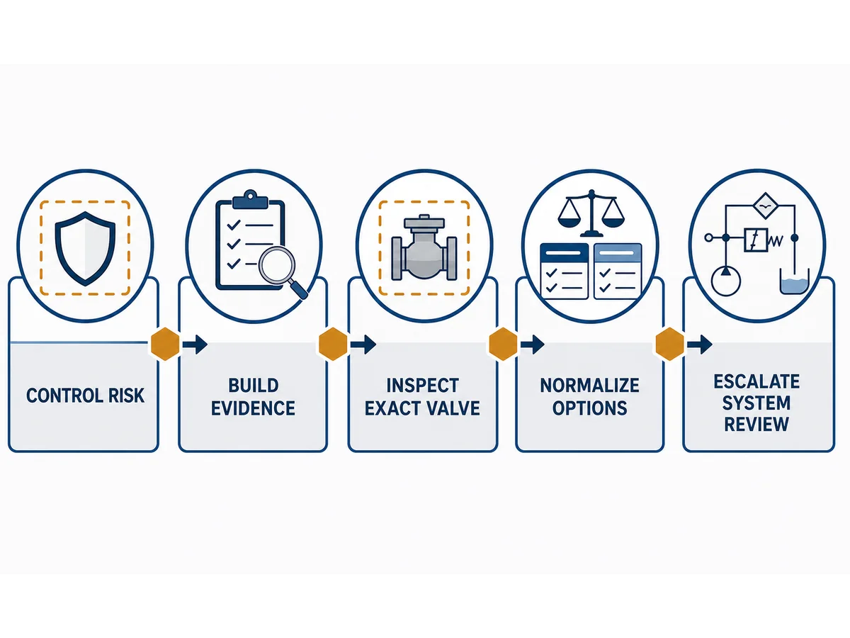
Flowchart from risk control and evidence collection to exact valve inspection, option review and system analysis
Example corrective workflow. Site procedures and responsible engineering approval remain controlling.

Quando la sostituzione della valvola può essere appropriata

Replacement may be defensible when evidence shows that:

  • the exact valve cannot remain stable across the required operating envelope;
  • inspection finds non-recoverable damage or unacceptable wear;
  • approved orientation or installation requirements cannot be met;
  • the model’s dynamic evidence is inadequate for the transient consequence;
  • or normalized alternatives demonstrate a better fit after system review.

Replacement is an evidence-based conclusion. Define acceptance criteria and post-installation verification for the new valve.

Supplier Proposal and Technical Bid Normalization

Comparison field Existing valve/condition Corrective proposal A Corrective proposal B Evidenza richiesta
Exact model and construction Record State State Disegno controllato
Minimum, normal, and maximum flow Record Di ritegno Di ritegno Input di progetto
Opening position/stability basis Unknown or record Provide Provide Model data or calculation
Cv/Kv or pressure-loss curve Record if available Provide Provide Stated fluid and conditions
Spring, cracking, and travel basis Record Provide Provide Controlled supplier data
Closing/reverse-velocity basis Record if available Provide Provide Evidenza dinamica
Orientation and installation limits Record Conferma Conferma Approved IOM/drawing
Internal component materials Record Provide Provide Component schedule
Inspection, tests, and documents Record Definire Definire Order requirement
Deviations and residual risks Record Disclose Disclose Responsible disposition

Align the technical basis before comparing price or nominal type. A lower-loss option may lack stable-opening evidence; a fast-closing option may lack evidence for the system deceleration case.

Standard e registrazioni di prova: cosa dimostrano e cosa non dimostrano

API’s current public updates identify API 594 as a check-valve standard and list the ninth edition dated February 2022. Because API work on later editions can proceed before publication, the purchaser should verify the effective edition and project applicability at the time of order. A construction standard reference does not establish the dynamic performance of a particular valve in a particular system.

ISO 5208:2015, confirmed current by ISO in 2025, addresses examinations and tests for pressure-boundary integrity, closure tightness, and structural adequacy within its stated scope. Those tests do not establish minimum stable flow, chatter-free operation, reverse velocity, slam severity, or pump protection.

Document or evidence What it may support Cosa non dimostra
Applicable check-valve construction standard Construction and purchaser requirements within verified scope Stable opening or system transient response
Pressure/seat leakage test report Specified pressure-boundary or closure acceptance Original cause of chatter or slam
Face-to-face dimensional reference Dimensional interchangeability within applicable scope Hydraulic or dynamic suitability
Supplier opening/pressure-loss curve Model behavior within its stated test/calculation basis Performance outside that basis
Reverse-velocity or closing-response evidence Dynamic comparison for stated model and deceleration cases Complete system pressure response without system analysis
Site pressure and flow record Actual event behavior at instrument locations Valve internal motion unless it is measured or otherwise verified

Tie standards, reports, drawings, and calculations to the exact model, revision, order, and acceptance scope. A general certificate or standard number is not order-specific evidence.

Pacchetto dati per la risoluzione dei problemi delle valvole di ritegno
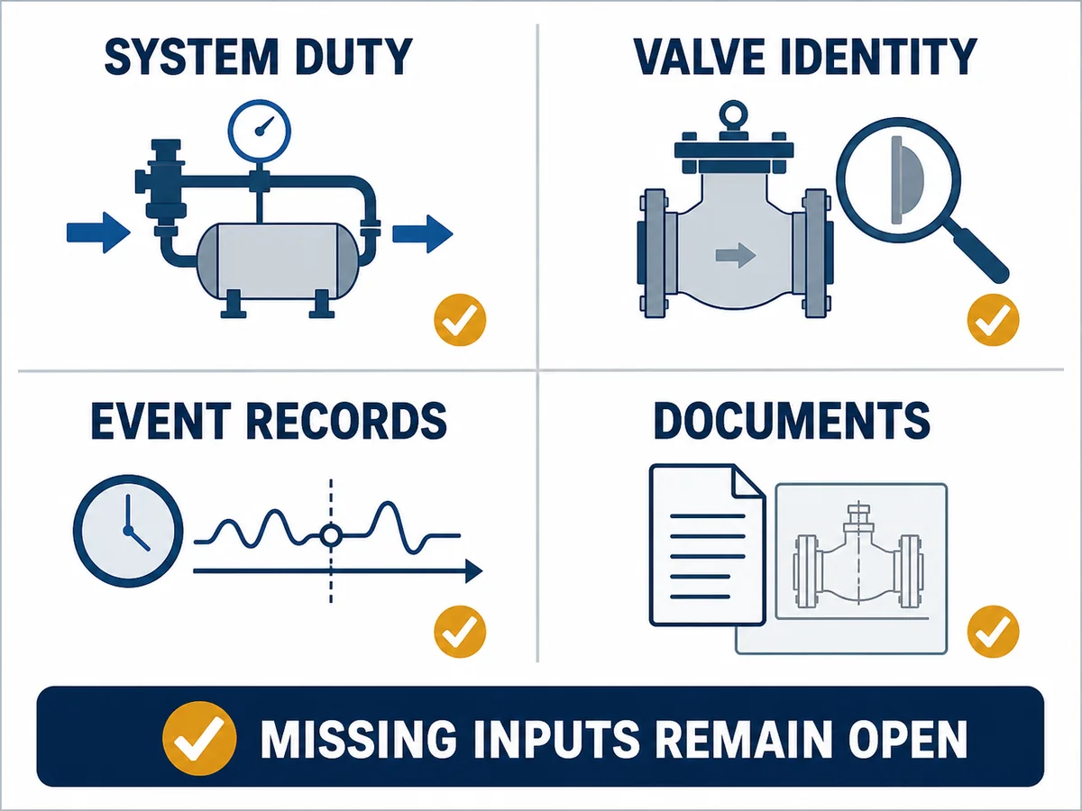
Check valve troubleshooting checklist covering system duty, valve identity, event records and documents
Example troubleshooting checklist. Missing fields remain project inputs and may prevent a defensible corrective decision.

System Duty

  • medium, phase, density, temperature, solids, and gas fraction;
  • operating and design pressure;
  • minimum, normal, and maximum flow;
  • allowable steady pressure loss and transient limit;
  • pump or compressor curve and operating sequence;
  • line profile, static head, orientation, and nearby fittings;
  • normal cycling plus startup, shutdown, and trip cases.

Valve Identity

  • manufacturer, exact model, size, pressure class/PN, and end connection;
  • construction, flow arrow, and approved orientation;
  • spring, cracking, travel, and opening-position data where applicable;
  • GA/sectional drawing and IOM;
  • body, closure member, hinge/pin/guide, spring, seat, and hardfacing schedule;
  • operating and maintenance history.

Event Evidence

  • timestamped pressure, flow, equipment command, vibration, acoustic, and motion records;
  • as-built piping and support information;
  • safely obtained post-isolation photographs;
  • inspection and test records;
  • details of recent process, piping, valve, pump, controls, or maintenance changes.

Verificare la correzione prima della chiusura del caso

Define acceptance criteria before implementation. Within the authorized commissioning plan, repeat the relevant minimum, normal, maximum, startup, shutdown, trip, and cycling cases.

Verify both valve behavior and system response. Record pressure, flow, motion or vibration evidence, leakage or functional results where applicable, component settings, residual risks, deviations, and approved documents. Do not call the case resolved because the noise disappeared during one observation.

Conclusione

Check valve chatter, slam, and water hammer require different evidence. Start by classifying the event, building a synchronized timeline, and separating closure-member motion from the wider system response. Then inspect the exact valve, test the possible causes, normalize corrective proposals, and verify the result across the required operating cases.

There is no universally correct valve family or one-step fix. The gamma di valvole di ritegno industriali provides the commercial route, while final selection and corrective approval depend on the exact model, complete system duty, controlled documents, and responsible engineering review.

Request a Check Valve Troubleshooting Review

Send the event timeline, medium and phase, pressure and temperature, minimum/normal/maximum flow, pump or compressor curve and shutdown sequence, piping profile and orientation, exact valve model and drawing, vibration/acoustic or pressure evidence, inspection findings, and required corrective documentation.

Request a check valve troubleshooting review

Submission starts an evidence review. It does not by itself confirm root cause, final valve sizing, transient acceptance, pump protection, or an approved corrective package.

Domande frequenti

What is the difference between check valve chatter and slamming?

Chatter is repeated unstable movement during an operating period. Slam is a closing impact, often associated with rapid deceleration or reverse-flow exposure. Water hammer is the related system pressure wave and needs separate confirmation.

Una valvola di ritegno sovradimensionata può causare vibrazioni (chatter)?

It can contribute when the required flow cannot hold the exact closure member in a stable position, but oversizing should not be diagnosed from line size or noise alone. Compare the operating points with exact-model opening data and inspect other possible causes.

Does a loud bang prove the check valve caused water hammer?

No. The sound may coincide with valve closure, pipe movement, or a pressure wave generated elsewhere. Use synchronized pump, flow, pressure, vibration, and valve-event data.

Will a non-slam check valve always stop surge?

No. “Non-slam” is not a system-performance guarantee. Exact-model closing evidence and the piping-system transient must support the conclusion.

What field data should be collected before replacing a check valve?

Collect the event timeline, operating flow and pressure cases, pump/compressor sequence, line profile, valve identity and orientation, model data, vibration/acoustic or pressure records, inspection findings, and recent system changes.

Can changing the spring or using a smaller valve solve chatter?

Either may be an evaluation direction, but both can change opening pressure, pressure loss, stable operation, and closing response. Review the exact option against the full duty before implementation.

When is hydraulic transient analysis needed?

It may be warranted for material pressure excursions, high static head, long lines, repeated trips, multiple pumps, hazardous service, or other consequences that cannot be closed through simple field evidence.

Which tests prove that the corrective action worked?

No single test covers every case. Use project-defined acceptance criteria and verify the relevant operating and trip cases, valve behavior, system pressure response, leakage or functional results, and documentation after the correction.

Riferimenti ingegneristici e limiti

This article supports preliminary diagnosis and RFQ preparation. It does not replace the approved datasheet, project specification, controlled standard editions, IOM, risk assessment, hydraulic transient study, site procedures, or responsible-engineer approval.

Lascia un commento

Il tuo indirizzo email non sarà pubblicato. I campi obbligatori sono contrassegnati *

it_ITItalian
Torna in alto