Check Valve Chatter vs Slamming: Causes, Field Evidence and Corrective Direction

Check Valve Troubleshooting Guide

Check valve chatter and check valve slam both involve closure-member movement, but they occur under different operating conditions and require different evidence. Noise alone does not prove oversizing, internal damage or an incorrect valve type.

Diagnose the event by when it occurs, not only by how it sounds.

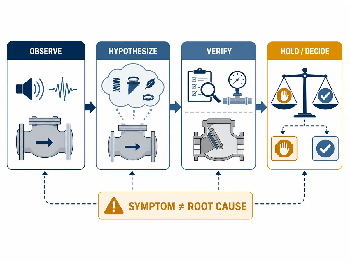
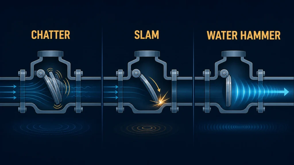
Chatter is repeated unstable movement during flow; slam is a closure event associated with deceleration or reversal. Correlate either symptom with operating history, equipment sequence, valve movement, piping layout and inspection evidence before approving a change.

Page scope This page diagnoses chatter and slam observed in an installed system. It does not perform check valve sizing or replace a valve-construction comparison. Use exact-model data and the project engineering process for final selection.

Immediate Engineering Triage Before Root-Cause Work

Before continuing the investigation or changing the valve, the plant’s authorized team should classify the evidence and potential consequence.

Monitored investigation

Low-consequence symptom

No recorded pressure excursion, support movement, containment concern, process-affecting reverse leakage or indication of internal breakage. Collect synchronized data only under an approved monitoring plan.

Controlled inspection

Evidence of deterioration

Repeated chatter, increasing vibration, changed pressure loss, reverse leakage or suspected component wear. Plan isolation and inspection under approved depressurization, draining or purging procedures.

Engineering escalation

Potential system consequence

Pressure excursions, severe support movement, suspected broken internals, containment risk or repeated protective trips require prompt review under the site’s shutdown and safety process.

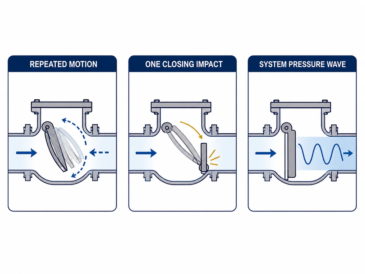
Check Valve Chatter and Slamming Are Different Events

What Check Valve Chatter Means

Chatter is repeated or unstable motion of the closure member during flow, often between a partial-open position, the open stop and the seat.

  • Repeated tapping or metallic rattling
  • Noise that changes with flow rate
  • External lever or position-indicator movement
  • Guide, hinge, stop, spring or seat wear

What Check Valve Slamming Means

Slam is a closure event in which decelerating or reversing flow is stopped rapidly as the closure member seats.

  • A heavy event after pump shutdown or trip
  • A pressure pulse following deceleration
  • Pipe or support movement
  • Repeated events during parallel-pump switching
Diagnostic boundary Internal damage may be a cause or a consequence. A worn guide can create unstable movement, while repeated unstable movement can also create guide wear.

Quick Diagnostic Table: Chatter vs Slamming

Diagnostic field Chatter direction Slamming direction Evidence needed
Typical timing During normal, variable or low-flow operation During shutdown, trip or flow reversal Timestamped operating record
Sound pattern Repeated tapping, rattling or oscillation One or several heavy closure events Acoustic record linked to equipment status
Flow condition Unstable, pulsating or below stable-opening range Rapidly decelerating or reversing Flow trend and shutdown sequence
Valve movement Repeated partial travel One closing stroke following deceleration Position indication or safe external observation
Pressure behavior Fluctuating differential pressure may be present A transient pressure event may be present Upstream and downstream pressure traces
Main review Stable opening and installation Closing dynamics and system transient Exact-model and piping-system data

Common Causes of Check Valve Chatter

Insufficient Force to Maintain Stable Opening

Cracking, initial opening and stable full opening are different conditions. A line-size selection may leave the closure member at unstable partial travel, especially at minimum flow.

Oversizing is one possible cause, but confirm it against minimum, normal and maximum flow plus exact-model data. Use the check valve sizing and closing-dynamics guide for the full sizing workflow.

Variable or Pulsating Flow

Variable speed, compressor pulsation, unstable control, cyclic demand or pump switching may move the closure member repeatedly. Confirm that the motion follows the operating fluctuation.

Disturbed Inlet Flow

Nearby elbows, tees, reducers, pump discharge or control equipment may produce non-uniform inlet flow. Apply the exact model’s installation instructions rather than one universal straight-run rule.

Incorrect Installation Orientation

Confirm flow direction, horizontal or vertical approval, shaft position and whether gravity or spring force is required. Physical fit does not prove dynamic suitability.

Internal Friction, Wear or Obstruction

Inspect for hinge or guide wear, galling, deposits, foreign material, spring damage, loose parts, distortion, stop damage and seat wear. Decide whether damage caused the instability or resulted from it.

Accessory Condition or Adjustment

Lever, counterweight, spring, travel-stop and dashpot settings affect opening and closure. Do not adjust them from noise alone.

Common Causes of Check Valve Slamming

Rapid Pump or Compressor Shutdown

Closing response depends on equipment inertia, static head, line length, friction, fluid properties and interaction with other operating units—not valve type alone.

Reverse Velocity Before Full Closure

A typical liquid-pipeline sequence is forward-flow decay, closure-member movement, possible reverse flow after the flow passes through zero, and rapid interruption of that reverse flow. The dynamic-characteristics method relates reverse velocity at closure to liquid-column deceleration, but the result remains model- and system-specific.

Service boundary The reverse-velocity sequence described here is primarily a liquid-pipeline model. Gas, steam, compressible-fluid and two-phase systems require service-specific analysis because pressure-wave behavior and equipment interaction can differ materially.

Long Travel, Moving Mass or Delayed Movement

Mass, travel, hinge geometry, friction, spring force, orientation and deposits affect closure. Shorter travel or spring assistance may help, but faster closure is not a universal solution.

Mismatch Between Valve and System Dynamics

Labels such as “silent,” “non-slam,” “nozzle” or “axial-flow” do not approve a replacement. Verify flow range, loss, stable opening, closure data, orientation, medium, fouling and maintainability.

Where a construction change is justified, compare the available industrial check valve range only after the operating mechanism and required dynamic response have been defined.

Parallel Pumps and Complex Piping

Common headers, bypasses, elevated mains, long pipelines and interacting valves may require system transient analysis rather than a valve-only explanation.

Field Evidence to Collect Before Naming the Cause

Operating Evidence

  • Date and time of each event
  • Valve type, exact model and nominal size
  • Medium, phase and operating temperature
  • Minimum, normal and maximum flow
  • Operating pressure and measured differential pressure, where available
  • Pump or compressor state, speed and load
  • Control-valve position and operating frequency

Dynamic Evidence

  • Upstream and downstream pressure trends
  • Flow trend
  • Pump-speed or motor trip signal
  • Compressor load or unload signal
  • Vibration and acoustic timing
  • Valve-position indication
  • Shutdown or trip sequence

Installation Evidence

  • Actual flow direction and orientation
  • Hinge, shaft or guide-axis position
  • Nearby elbows, tees, reducers and control valves
  • Distance from the pump or compressor
  • Pipe and valve support condition
  • Modifications since commissioning

Internal Inspection Evidence

After approved isolation, depressurization, draining or purging, inspect seat contact, impact marks, guide wear, hinge and shaft condition, spring condition, closure-member deformation, stop damage, deposits, corrosion, erosion, galling and loose components.

Evidence quality ladder
  1. Observation: sound, operator report or unsynchronized video; useful for locating the event, not approving a design change.
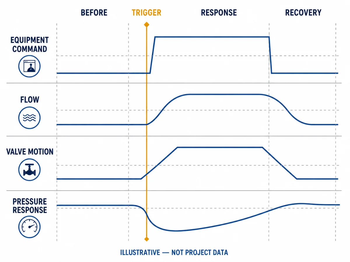
  2. Synchronized record: flow, pressure, equipment state, valve indication and vibration on one time base.
  3. Model and installation evidence: exact drawing, IOM, performance data, orientation limits and piping layout.
  4. Physical or system confirmation: inspection, calibrated transient data or a reviewed model.

Approval rule: higher consequences require stronger evidence before changing the valve, equipment sequence or piping.

Field Evidence–Cause–Verification Matrix

Field observation Possible cause direction Supporting evidence Evidence that weakens it Corrective direction
Repeated noise only near minimum flow Unstable opening Noise stops as flow increases; position is unstable at low flow Noise continues at stable high flow Review actual flow envelope and valve sizing
Heavy event after every pump trip Closing transient Pressure event follows pump-speed decay Noise occurs during steady forward flow Review shutdown sequence and dynamic closure
Chatter began after piping modification Inlet-flow disturbance New elbow, reducer or control valve is close to the valve Local flow path did not change Review piping arrangement and model-specific installation limits
Noise persists at every operating point Wear, friction or obstruction Inspection finds a guide, hinge, spring or debris problem Internal parts move freely and show no abnormal wear Repair verified damage or investigate another source
Severe pipe movement occurs after closure Pressure transient Pressure trace and support reaction align with the event No corresponding transient is measured Perform piping-system surge review
Reverse leakage appears after repeated events Seat or closure damage Seat inspection confirms impact, erosion or distortion Seat remains within applicable acceptance criteria Repair damage and correct the initiating mechanism

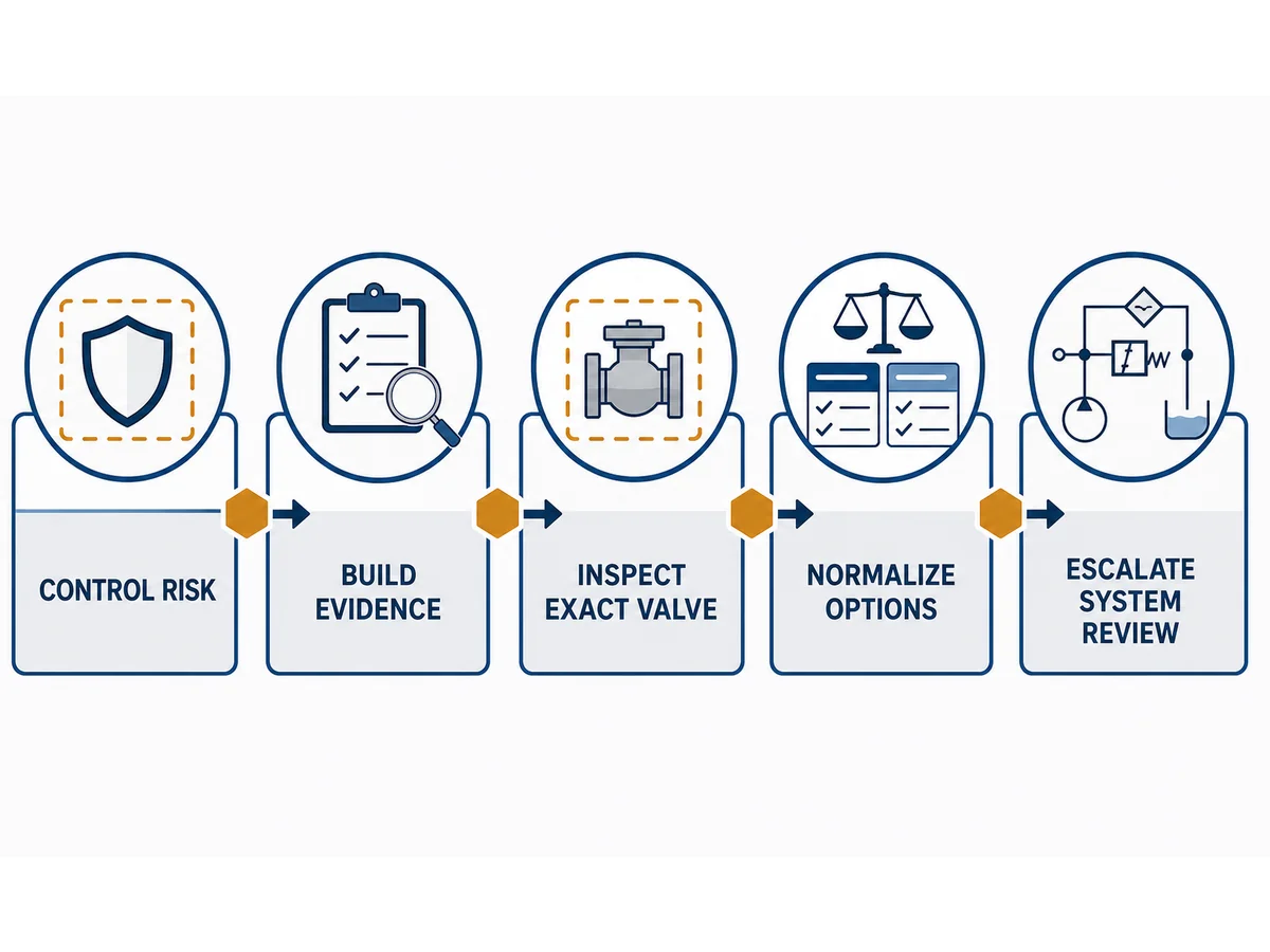
Corrective Direction: Use a Hierarchy, Not a One-Step Replacement

  1. Confirm the symptom. Separate check valve movement from pump vibration, cavitation, loose external linkage, support movement and adjacent equipment noise.
  2. Verify the operating envelope. Compare actual minimum, normal and maximum flow, pressure differential, equipment speed and trip sequence with the design basis.
  3. Correct installation or local piping issues. Restore approved orientation, review nearby disturbances, correct support problems and follow the exact IOM.
  4. Inspect and repair verified damage. Identify approved parts, wear limits, materials, seat acceptance and post-assembly testing.
  5. Recheck valve size and construction. Use exact-model pressure-loss, stable-opening, travel, spring, orientation and dynamic data.
  6. Review pump or compressor control. Examine coast-down, sequencing, parallel-unit coordination, bypass behavior and control-valve operation.
  7. Escalate to transient analysis where required. Use system-level analysis for repeated damaging events, long lines, high static head, rapid trips or interacting equipment. A 2024 review of check valves in unsteady liquid flow explains why dynamic valve behavior must be evaluated within the connected piping network rather than as an isolated component.
Engineering approval gate Do not approve a size, spring, counterweight, dashpot or valve change from sound alone. Confirm the operating envelope, exact construction, installation, internal condition and system response.
No-data, no-change gate Record unknown model data, operating conditions and acceptance criteria as technical deviations; do not fill them with generic assumptions before changing size, travel, spring, damping or sequence.

When Valve Replacement May Be Appropriate

Replacement may be justified when evidence shows that the installed valve cannot remain stable across the required flow range, cannot meet the approved closing response, has damage beyond repair limits or cannot satisfy orientation, maintenance or model-specific performance requirements.

The replacement must still be checked for pressure-temperature rating, materials, connections, dimensions, leakage, capacity, stable opening, closing response, installation, testing and documentation. The swing versus lift check valve comparison supports preliminary screening but does not replace exact-model approval.

Supplier Evidence Required for a Corrective Proposal

Supplier submission Why it matters Acceptance boundary
Exact offered-model drawing Confirms construction, movement, orientation and replaceable parts Must match the quoted valve
Pressure-loss or flow curve Supports operating-point review Generic family data may be insufficient
Stable-opening guidance Supports chatter assessment Assumptions and orientation should be stated
Dynamic closing information Supports slam assessment Size, construction and system basis should be identified
Installation and maintenance manual Confirms approved mounting and service requirements Must match the supplied design
Inspection and test scope Defines manufacturing acceptance Does not prove installed dynamic performance
Technical deviation schedule Identifies differences from the datasheet Deviations must be resolved before approval
Material, trim and spring details Supports compatibility, wear and repair review Must be checked against medium, temperature, solids and environment
Repair limits and replacement-part criteria Supports a controlled return-to-service decision Must be model-specific and linked to inspection findings
Selection basis and stated assumptions Shows how the proposed correction was derived Must identify missing project data and excluded operating cases
Post-change verification plan Defines how the correction will be checked in service Must include measurable acceptance criteria and a rollback path

Corrective Proposal Comparison Matrix

Compare proposals on one technical basis; the lowest-cost component change may not be the lowest-risk system correction.

Proposed direction Minimum technical basis Approval question Common hidden risk
Operating-envelope change Confirmed minimum flow, equipment duty and process constraints Can the required operating range be maintained without transferring risk elsewhere? The process cannot reliably remain inside the proposed range
Installation or support correction As-built orientation, local piping geometry, support survey and IOM Does the change correct the verified disturbance or movement mechanism? The valve remains dynamically mismatched after the local correction
Internal repair Inspection findings, wear limits, approved parts and repair procedure Is the damage the initiating cause, a consequence or both? New parts fail again because the operating cause remains
Resize or change valve construction Actual flow range, pressure loss, stable-opening and closing-response data Does the offered model cover every required operating and trip case? Improved closure response but excessive pressure loss, fouling or maintenance difficulty
Pump, compressor or control-sequence change Equipment curves, coast-down or unload behavior, logic and system boundaries Is the revised sequence safe for all interacting equipment? A valve symptom is reduced while another transient or control problem is created
System transient mitigation Reviewed model, boundary conditions, measured event data and acceptance limits Does the proposal reduce the governing pressure consequence with adequate margin? Incorrect boundary assumptions produce a misleading solution

Standards and Test Records: What They Do and Do Not Prove

API 594

API’s official advisory confirms publication of API Standard 594, ninth edition, for specified check-valve constructions. Confirm the project-required edition and scope; product-standard conformity does not prove installed dynamic performance.

ASME B16.34

ASME B16.34-2025 covers ratings, dimensions, tolerances, materials, examination, testing and marking for applicable new construction; it does not replace stability or transient assessment.

Pressure and Seat Testing

ISO 5208:2015 covers pressure-boundary integrity, closure tightness and closure-mechanism adequacy. Shop testing does not reproduce low-flow instability, disturbed inlet flow, coast-down, reverse velocity or system surge.

Testing boundary Shop shell, seat and functional tests are necessary acceptance evidence, but they are not proof that the installed system will be free from chatter or slam.

Check Valve Troubleshooting Data Pack
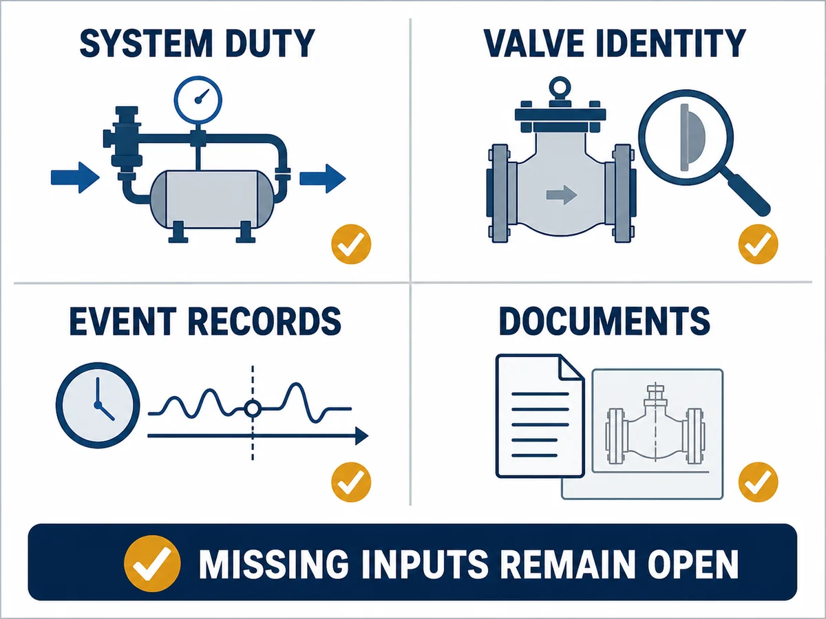
  • Valve type, model and drawing
  • Nominal size, class or PN
  • End connection and orientation
  • Medium, phase and solids
  • Operating and design temperature
  • Operating and design pressure
  • Minimum, normal and maximum flow
  • Pump or compressor type
  • Normal shutdown and trip sequence
  • Pressure, flow and vibration records
  • Piping layout and nearby disturbances
  • Internal inspection photographs
  • Maintenance and repair history
  • Applicable specification and acceptance criteria

Verify the Correction Before Closing the Case

A quiet first restart is not proof. Repeat the governing case, compare it with the baseline and confirm that no new pressure-loss, leakage, vibration or control problem appears.

Before the change

  • Define the symptom and governing event.
  • Capture baseline flow, pressure, vibration and equipment-state data.
  • Record internal condition and relevant wear.
  • Agree measurable acceptance criteria and responsible approvers.

After the change

  • Repeat normal, minimum-flow and relevant shutdown cases under approved procedures.
  • Compare synchronized records with the baseline.
  • Confirm leakage, pressure loss, support movement and valve indication.
  • Document deviations, residual risk, monitoring period and rollback action.
Verification item Baseline Post-change evidence Acceptance direction
Chatter or closure event Timestamp, frequency and operating condition Repeat test under the same relevant condition Event eliminated or reduced to the project’s approved criterion
Pressure response Upstream and downstream trend Comparable synchronized trace No unacceptable new excursion or transferred transient
Flow and pressure loss Normal and minimum-flow operating points Measured or validated post-change performance Required capacity retained within the approved pressure-loss limit
Mechanical condition Wear, leakage, support and linkage condition Inspection and monitored operating record No progressive damage, leakage or abnormal movement
Documentation Original drawing, IOM and maintenance record Approved as-built, test record and deviation closeout Configuration and acceptance basis are traceable

Conclusion

Check valve chatter and slamming are not interchangeable descriptions of a noisy valve. Chatter directs the investigation toward stable opening, flow, installation and internal movement; slam directs it toward deceleration, reverse velocity, closure response and piping-system transients.

The corrective action may involve operating changes, installation correction, repair, a different valve selection, equipment-control review or transient analysis. Approve the action from verified evidence, then compare post-change performance with the baseline.

Request Check Valve Troubleshooting Review

Send the exact model or drawing, size, class or PN, orientation, medium and phase, pressure, temperature, minimum-normal-maximum flow, equipment sequence, piping layout, synchronized records, inspection photos and acceptance criteria. State whether the request concerns operation, repair, replacement or transient review.

Request a Check Valve Review

Frequently Asked Questions

What is the difference between check valve chatter and check valve slam?

Chatter is repeated unstable movement during flowing conditions. Slam is a closure-related event more commonly associated with rapid deceleration or flow reversal. Field timing, pressure, flow and valve-movement evidence are needed to distinguish them.

Does an oversized check valve always chatter?

No. Oversizing may prevent stable opening, but pulsating flow, disturbed inlet flow, incorrect orientation, friction, deposits, wear and damaged components can produce similar symptoms.

Can check valve slamming be identified by sound alone?

No. The sound should be correlated with pump or compressor status, pressure traces, flow behavior, vibration, pipe movement and valve movement.

Will a spring-loaded check valve eliminate water hammer?

Not automatically. Spring assistance can change closing response, but the exact valve still needs to be matched to the installed system, actual flow range, orientation and service conditions.

Can pressure testing prove that a check valve will not chatter?

No. Shell and closure tests evaluate specified manufacturing acceptance conditions. They do not reproduce the installed flow envelope or pump-shutdown dynamics.

When is transient analysis needed?

It should be considered for repeated damaging events, rapid trips, long pipelines, high static head, interacting pumps, severe support movement or uncertain pressure consequences.

Should a noisy check valve be removed from service immediately?

The decision must follow the plant’s authorized risk and safety process. Measured pressure excursions, severe pipe or support movement, suspected broken internals, containment risk, reverse leakage affecting the process or repeated protective trips require prompt engineering review and may justify a controlled shutdown or isolation.

What information should be sent to a check valve supplier?

Send the exact valve model or drawing, size, orientation, medium, pressure, temperature, minimum-to-maximum flow, equipment sequence, piping layout, event timing, operating records and inspection photographs.

Engineering References and Limits

  • API 594 ninth-edition advisory — official publication notice; confirm the project-required edition and scope.
  • ASME B16.34-2025 — ratings, construction, examination, testing and marking scope.
  • ISO 5208:2015 — pressure-boundary and closure-testing scope.
  • Dynamic Characteristics of Check Valves — liquid pumping-system discussion of reverse velocity and valve closing characteristics.
  • A Review of Check Valves in Unsteady Flow — 2024 review of liquid-flow behavior, analysis and design.

This framework is not a project diagnosis. Exact pressure-loss, stable-opening and closing data must come from the offered model; severe events require project engineering and plant safety review.

Engineering note Prepared by the Raymon Valve Technical Content Team. It does not replace the project datasheet, exact IOM, reviewed transient study or responsible-engineer approval.

Review the broader industrial check valve range or request a project review through the contact page.

Share:

Leave a Comment

Your email address will not be published. Required fields are marked *

want totalk
with us?

Leave your details and one of our experts will contact you!

en_USEnglish
Scroll to Top

Contact us

Please fill out this form with a brief description of your issue and we will get back to you as soon as possible.