
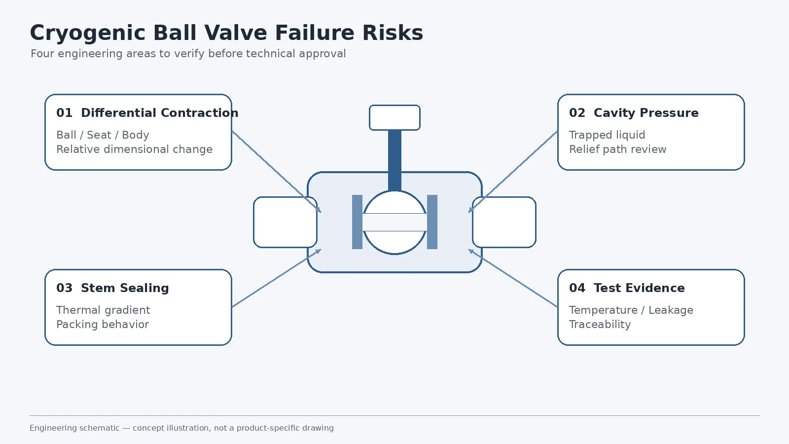
For project screening, start with the complete operating envelope rather than a product label. The proposed valve should be checked against the medium and phase, minimum design temperature, pressure and differential-pressure cases, ball support arrangement, seat system, packing, cavity-relief philosophy, operation method and required inspection documents. For broader construction choices, see the Ball Valve Selection Guide, the current ball valve product family, and Raymon Valve’s Cryogenic Valves engineering solution.
Why Cryogenic Ball Valve Failure Is More Than a Low-Temperature Problem
A cryogenic ball valve is a system of interacting components. The body, ball, seats, stem, packing, gaskets and bolting may use different materials, geometries and loading methods. As the valve cools from ambient temperature toward its minimum design temperature, these parts do not necessarily contract by the same amount or at the same rate.
At the same time, process fluid may remain trapped inside the body cavity. The stem provides a thermal path between the cold internal components and the packing and operator. Seat loading that was acceptable at ambient temperature may also change during cooldown.
| Failure Risk | Physical Mechanism | Possible Consequence | What the Buyer Should Verify |
|---|---|---|---|
| Differential contraction | Ball, seat, body and stem dimensions change differently | Seat-load change, leakage or higher torque | Material pairing, clearances, seat design and low-temperature test evidence |
| Cavity pressure | Cryogenic liquid is trapped and later warms | Body-cavity pressure increase | Seat relief direction, cavity-relief path and external relief requirement |
| Stem sealing | Thermal gradient reaches the stem and packing system | External leakage or packing-performance change | Stem extension, packing location, materials and test scope |
| Seat behavior | Seat properties and contact loading change at low temperature | Shutoff leakage or excessive friction | Seat material, preload philosophy and leakage acceptance |
| Test mismatch | Test conditions do not represent the specified service | Incomplete evidence of suitability | Test temperature, procedure, leakage limits and valve identification |
The practical review question is: what can fail, what design feature is intended to control that failure, and what evidence verifies that feature for the proposed valve?
Differential Contraction: Why the Ball, Seat, Body and Stem Do Not Move Together
What Differential Contraction Means in a Ball Valve
When temperature falls, metallic and non-metallic valve components contract. The magnitude of that dimensional change depends on material, geometry and temperature change. A ball valve may combine a metallic body, ball, stem and seat carrier with polymeric, composite or metallic seating elements. These parts are assembled with specific clearances and loading relationships at ambient temperature.
At cryogenic temperature, the relative dimensions can change. What matters is not simply whether each material can tolerate the temperature independently, but whether the assembled valve maintains the intended relationship between the ball, seats and body.
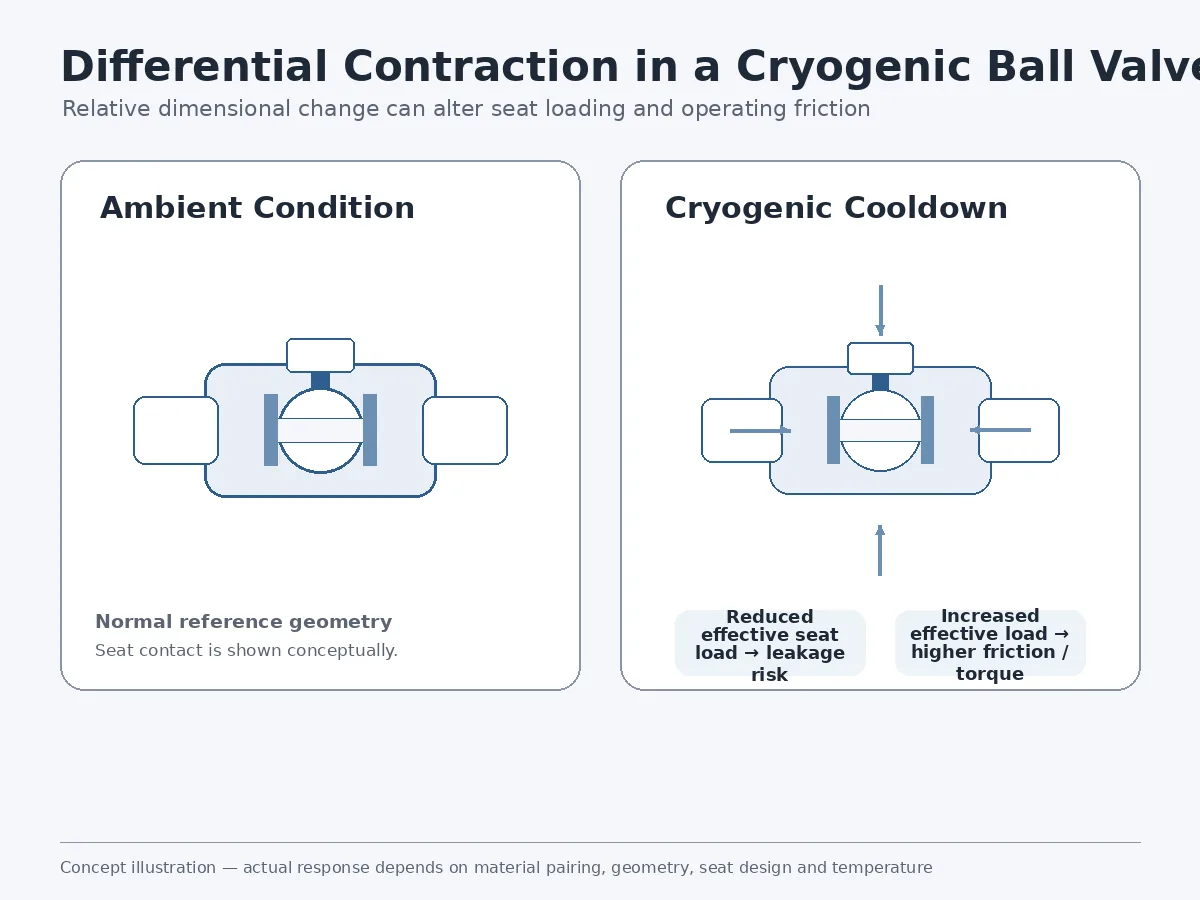
Possible effects include reduced seat contact pressure, increased seat loading, altered stem or ball alignment, higher operating friction, changed breakaway torque or leakage during thermal cycling. These are design-dependent risks rather than guaranteed outcomes.
Too Little and Too Much Seat Load Can Both Be Problems
If effective seat loading falls during cooldown, sealing contact may become insufficient for the specified shutoff requirement. If loading becomes excessive, friction may increase, seat stress may rise and valve operation may become more difficult. Cryogenic seat design therefore has to balance sealing force with friction, deformation and operating torque.
A seat material name alone is not enough for approval. Specifying PTFE, PCTFE, a reinforced polymer or a metal seat does not by itself define cryogenic performance. The review should consider minimum design temperature, pressure, differential pressure, ball support, seat geometry, loading method, material properties, allowable leakage, cycling and the required verification evidence.
For a product-specific engineering route, review the current Cryogenic Ball Valve page, then confirm the final construction against the actual project datasheet and purchase specification.
Trapped Cavity Pressure: A Critical Risk Between the Seats
How Liquid Can Become Trapped
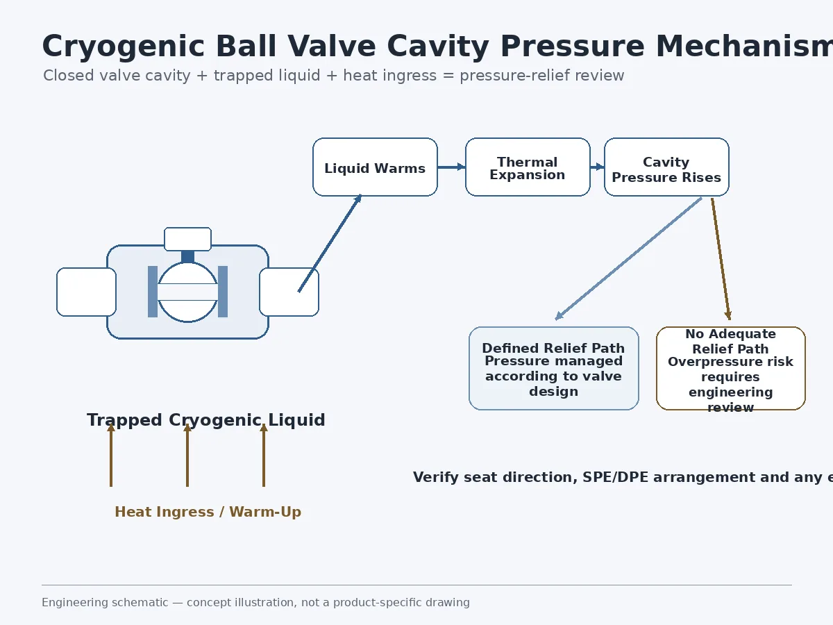
When a ball valve is closed, a volume can remain between the upstream and downstream seats inside the body cavity. What happens to that trapped volume depends on the valve construction and seat arrangement. In trunnion-mounted designs, single-piston-effect and double-piston-effect seat behavior can materially affect the path through which cavity pressure can or cannot be relieved.
Why Warm-Up Matters
A cryogenic valve may later receive heat from the surrounding environment, piping or shutdown conditions. If liquid is trapped in a closed cavity and its temperature rises, thermal expansion can increase cavity pressure. The actual pressure response depends on the fluid state, trapped volume, temperature change and available relief path.
“Self-Relieving Seat” Is Not a Complete Specification
A datasheet statement such as “self-relieving seat required” does not fully define the required behavior. The purchaser should establish which seat provides relief, the direction of relief, the pressure source, the SPE/DPE arrangement, whether isolation requirements restrict seat-based relief, whether external cavity relief is required, where that relief is routed and how the function will be verified.
A sectional drawing is particularly valuable because it allows the engineering team to review seat orientation, cavity arrangement and the proposed pressure-relief path.
Stem and Packing Sealing: Managing the Thermal Path
Why the Stem Matters
The valve stem mechanically connects the internal ball to the external operator or actuator. It also provides a path for heat transfer between the cold valve internals and the upper stem, gland and packing region. If the packing region becomes colder than intended, sealing characteristics can change. Thermal cycling can also affect gland loading and packing response.
Potential concerns include packing contraction, change in gland load, stem-seal leakage, external condensation or icing, altered stem friction and repeated cold/warm cycling effects. Seat leakage and stem leakage should be treated as separate failure modes because they involve different sealing interfaces and may require different acceptance criteria.
Why Extended Stems or Bonnets Are Used
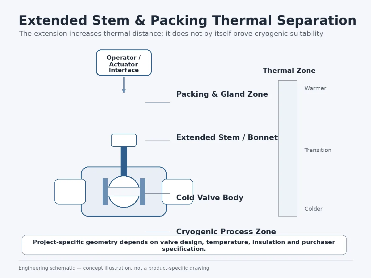
Cryogenic valves commonly use an extended stem or body/bonnet extension to increase thermal distance between the cold process zone and the packing or operating interface. The objective may include keeping the packing farther from the coldest region, reducing thermal influence on the gland and packing, accommodating insulation and maintaining operator or actuator clearance.
An extended bonnet should not be treated as proof of cryogenic suitability by itself. Extension geometry depends on valve size, construction, insulation, service temperature, applicable standard and purchaser specification.
Cryogenic Seat Leakage and Operating Torque Are Connected
Ball valve shutoff and operating torque are not independent. Increasing seat contact load may improve sealing under one condition, but it can also increase friction between the seat and ball. At cryogenic temperature, differential contraction may alter this relationship further.
The engineer should review both leakage performance and operating torque for the relevant service condition. Important cases may include breakaway torque, running torque, end-to-close torque, maximum differential pressure and temperature-dependent torque.
Thermal Cycling Can Reveal Problems That One Cold Test May Miss
Cryogenic service is not always a single cooldown followed by permanent steady-state operation. A valve may experience cooldown, stabilization, low-temperature operation, shutdown, warm-up and repeated service cycles. During this sequence, seat loading, packing load, gasket behavior and dimensional relationships can change and partially recover.
A single cold leakage reading therefore answers only the question defined by that particular test. Where cycling is important, the purchaser should determine whether the project requires repeated cold/warm cycles, valve operation during the test or another qualification sequence. Cycle count and acceptance criteria should come from the applicable standard and project specification rather than an arbitrary generic requirement.
What Cryogenic Testing Actually Proves — and What It Does Not
Testing terminology must remain precise. Shell, closure/seat, functional, cryogenic production, type, NDE, PMI and fugitive-emission activities answer different questions; passing one does not automatically prove another. Use the dedicated Cryogenic Valve Testing & Qualification resource for detailed cooldown, stabilization, leakage measurement and qualification planning. This article focuses on whether the submitted evidence actually closes the identified failure risk.
Ambient Shell and Seat Testing
An ambient pressure test can provide evidence of pressure-boundary integrity and seat performance under the specified ambient test condition. It does not automatically demonstrate shutoff performance at cryogenic temperature, differential-contraction behavior, cryogenic stem-packing performance, low-temperature operating torque or performance after thermal cycling.
ISO 28921-1:2022 — Production Requirements
ISO 28921-1:2022, Industrial valves — Isolating valves for low-temperature applications — Part 1: Design, manufacturing and production testing, covers low-temperature isolation-valve design, manufacturing and production testing within its stated scope. It should be treated as one layer of the specification rather than proof that a proposed valve is automatically suitable for every cryogenic service.
ISO 28921-2:2015 — Type Testing
ISO 28921-2:2015 addresses type testing rather than routine production testing. ISO currently lists the 2015 edition as the published edition while a revision project is under development, so the contractual edition should be confirmed before purchase-order release.
ANSI/MSS SP-134-2025
ANSI/MSS SP-134-2025 provides additional cryogenic-valve requirements, including body/bonnet extension and other low-temperature design, fabrication, examination and pressure-testing considerations. It should be used with the applicable parent valve standard and project specification.
For detailed cooldown, stabilization, leakage measurement and qualification planning, use the dedicated Cryogenic Valve Testing & Qualification resource. For a broader map of design, dimensional, material and test requirements, see Valve Standards.
Do API 6D or API 608 Alone Prove Cryogenic Suitability?
No. API 6D and API 608 can define base ball-valve requirements within their respective scopes, but citing a product standard does not by itself close the low-temperature design and testing requirement.
Cryogenic standard / project specification → low-temperature-specific requirements
Purchaser datasheet → actual medium, phase, temperature, pressure, seat arrangement, leakage acceptance, operation and documentation scope
A line item such as “API 6D cryogenic ball valve” may therefore leave important technical requirements undefined.
Cryogenic Ball Valve Failure Verification Matrix
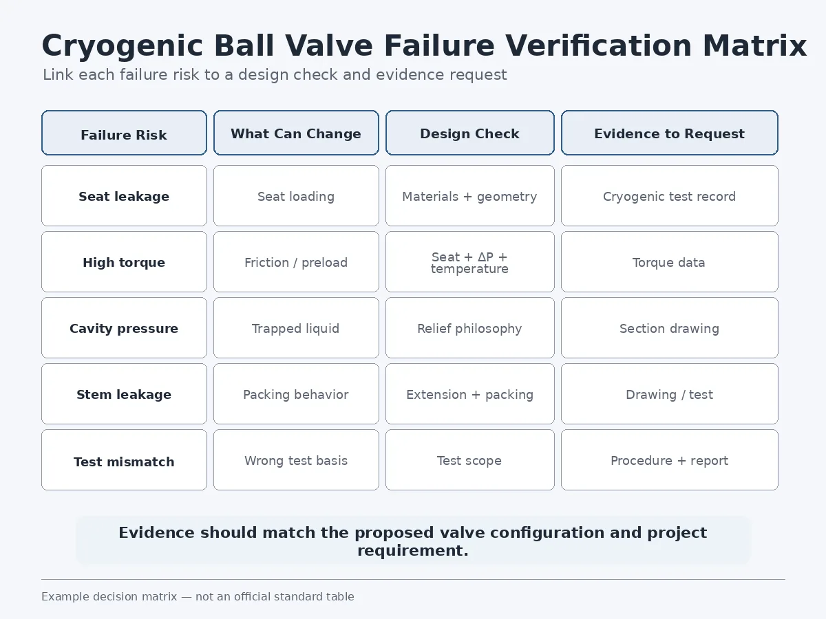
| Risk | Possible Cause | What to Review | Supplier Evidence |
|---|---|---|---|
| Seat leakage after cooldown | Differential contraction or inadequate seat load | Ball/seat materials, geometry and cold-test condition | Applicable cryogenic test report |
| High operating torque | Increased seat friction or thermal dimensional change | Seat design, differential pressure and temperature | Torque calculation or test data where required |
| Cavity overpressure | Trapped liquid with inadequate relief path | Seat arrangement and cavity-relief philosophy | Sectional drawing and engineering confirmation |
| Stem leakage | Packing response or gland-load change | Packing material, location and stem design | Drawing, specification and test record |
| Leakage after cycling | Repeated thermal movement | Test sequence and valve operation | Qualification or project test record |
| Incorrect relief direction | Seat configuration does not match pressure case | SPE/DPE direction and pressure source | Sectional drawing |
| Inadequate test evidence | Test differs from actual requirement | Temperature, pressure, procedure and acceptance | Approved test procedure and report |
What Should Be Included in a Cryogenic Ball Valve RFQ?
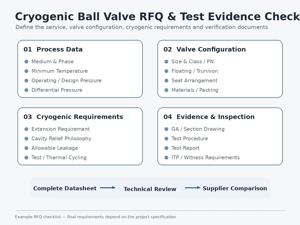
A useful cryogenic RFQ should give the supplier enough information to evaluate the complete service envelope. For the broader tag-level structure, use the ball valve datasheet requirements guide.
Process Data
- Process medium and composition where relevant
- Liquid, gas or two-phase condition
- Minimum design temperature and normal operating temperature
- Design and operating pressure
- Maximum differential pressure
- Startup and shutdown cases where relevant
Valve Configuration
- Valve size and Class / PN
- Floating or trunnion-mounted construction
- Full or reduced bore
- End connection
- Body, ball and stem materials
- Seat arrangement and seat material
- Packing and gasket requirements
- Manual or actuated operation
Cryogenic-Specific Requirements
- Minimum service or design temperature
- Stem or bonnet extension requirement
- Installation orientation and insulation interface
- Body-cavity pressure-relief philosophy
- SPE/DPE and flow-direction requirements
- Allowable leakage
- Cryogenic production or type-test requirement
- Thermal-cycling or operating verification where required
- Oxygen-service cleaning or contamination-control requirement where applicable
Inspection and Documentation
- Material certificates and traceability
- PMI or NDE where required
- Dimensional inspection
- Pressure-test records
- Cryogenic test procedure and report
- Inspection and test plan
- Purchaser or third-party witness points
- GA and sectional drawings
- Final manufacturing record dossier
How to Review Supplier Evidence Before Approval
Drawing Review
Check whether the drawing identifies the extended stem or bonnet arrangement, seat direction, body-cavity configuration, relief path, principal pressure-containing materials and operator or actuator interface.
Datasheet Review
Check whether the datasheet states the minimum temperature, design pressure, valve construction, seat material and arrangement, packing requirement, allowable leakage and required testing.
Test Procedure Review
Before accepting a cryogenic test scope, review the target test temperature, stabilization requirement, test pressure, valve orientation, valve operation during the procedure, leakage measurement method, acceptance criteria and required witness or hold points.
Test Report Review
The final report should be traceable to the supplied valve or a clearly defined qualified design. Useful fields include valve identification, configuration, test temperature, test pressure, measured leakage or acceptance result, test procedure reference, test date and witness information where required.
A generic certificate should not automatically be treated as evidence for every valve size, pressure class or construction.
Engineering Decision Flow
2. Confirm the base valve product standard
3. Review materials and differential-contraction risk
4. Review ball support, seat arrangement and cavity relief
5. Review stem, packing and thermal-extension arrangement
6. Define allowable leakage and relevant torque conditions
7. Define production and/or type-test requirements
8. Review drawings, procedures and valve-specific documentation
If the Valve Is Already in Service
Failure-risk review also matters after commissioning. New leakage or operating changes during cooldown should be treated as evidence to investigate rather than corrected by trial-and-error adjustment under live cryogenic conditions.
| Observed Symptom | Possible Review Direction | Immediate Evidence to Check |
|---|---|---|
| Seat leakage appears after cooldown | Seat loading, differential contraction, debris or damage | Leakage trend, temperature, differential pressure and prior test baseline |
| Operating torque rises materially | Seat friction, icing, alignment or actuator margin | Torque/current trend, temperature, pressure differential and actuator condition |
| Stem or packing leakage | Packing load, thermal gradient or stem-seal condition | Leak location, temperature profile, gland condition and maintenance history |
| Abnormal icing around the packing area | Thermal path, insulation condition or external leakage | Leak check, insulation boundary and surface-temperature pattern |
| Unexpected cavity-pressure indication | Trapped liquid, seat-relief path or blocked external relief | Valve position, seat arrangement, vent/relief line condition and pressure history |
Supplier Technical Evaluation: What Is Enough for Preliminary Approval?
A cryogenic valve quotation becomes easier to compare when every supplier is asked to answer the same technical questions. The objective is not to create a universal pass/fail rule, but to make differences in design assumptions, test scope and documentation visible before purchase-order release.
| Review Item | Minimum Evidence to Request | Why It Matters | Typical Approval Question |
|---|---|---|---|
| Minimum temperature | Datasheet value + applicable material/design basis | Confirms the proposal is tied to the actual service condition | Is the quoted construction reviewed for the specified minimum temperature? |
| Seat arrangement | Sectional drawing or clearly identified seat configuration | Controls isolation direction, cavity behavior and relief philosophy | Which seat can relieve cavity pressure, and in which direction? |
| Stem / packing arrangement | GA or sectional drawing showing extension and packing location | Allows review of the thermal path and insulation interface | Where is the packing located relative to the cold zone? |
| Leakage requirement | Defined acceptance criterion linked to a test procedure | Prevents “tight shutoff” from becoming an undefined commercial phrase | What leakage criterion will be measured, at what condition? |
| Operating torque | Manufacturer calculation or test data for the relevant configuration when required | Supports actuator review and avoids generic sizing assumptions | Does the torque basis reflect the seat design, differential pressure and temperature case? |
| Cryogenic testing | Applicable procedure + traceable report or qualification record | Distinguishes design intent from demonstrated test evidence | Is this type testing, production testing or another defined verification activity? |
| Traceability | Valve identification linked to drawings, materials and test records | Reduces the risk of accepting generic evidence for a different configuration | Can the report be traced to the proposed valve or qualified design family? |
Evidence Hierarchy: Design Intent vs. Verification Evidence
Not every document proves the same thing. During technical review, separate documents that describe the proposed design from documents that demonstrate a verified result.
| Document | What It Can Support | What It Does Not Prove by Itself |
|---|---|---|
| Datasheet | Specified service condition and proposed construction | Actual low-temperature performance |
| GA drawing | Overall arrangement, extension, dimensions and interfaces | Internal seat-relief behavior unless clearly shown |
| Sectional drawing | Seat direction, cavity arrangement and internal construction | Measured leakage or torque |
| Test procedure | Planned test sequence, condition and acceptance method | That the proposed valve actually passed |
| Test report | Recorded result for the identified test article | Automatic applicability to every other size, class or configuration |
| Material certificate | Material identity and traceability for listed components | Complete cryogenic valve suitability |
For procurement, this distinction is important because a technically complete bid should show both what is proposed and what evidence supports the proposed configuration.
Conclusion
Cryogenic ball valve approval should not depend on a “cryogenic” product label, an extended stem or a material name alone. The review should connect each important failure mechanism to both a design control and a verification method.
Differential contraction should lead to seat-load and clearance review; trapped liquid should lead to cavity-relief review; the stem thermal path should lead to packing and extension review; low-temperature sealing should lead to defined leakage acceptance; operating friction should lead to relevant torque verification; and qualification claims should lead to traceable type or production-test evidence.
This page is intended for preliminary engineering review, RFQ preparation and supplier technical comparison. It assumes an industrial isolation-ball-valve application and does not replace the project specification, piping-code requirements, responsible-engineer approval or manufacturer-specific calculations.
Project-specific confirmation is required for material compatibility, pressure-temperature rating, seat arrangement, allowable leakage, cavity-pressure management, operating torque, actuation, test scope and documentation. Where a supplier claims compliance, qualification or tested performance, the purchaser should request evidence that is traceable to the proposed valve configuration.
Prepared as technical content by Raymon Valve Technical Content Team; no individual professional license or third-party approval is implied. For related selection, standards, testing and troubleshooting resources, visit the industrial valve Knowledge Center.
Frequently Asked Questions
Why can a cryogenic ball valve leak after cooldown?
Cooldown can change the dimensional relationship between the ball, seats, body and stem. Depending on the materials, seat design and preload, differential contraction can reduce or increase contact loading. Leakage can also be influenced by pressure differential and thermal cycling.
Why is cavity pressure a concern in cryogenic ball valves?
Liquid can remain trapped between the valve seats. If that liquid later warms in a closed cavity, thermal expansion can increase cavity pressure. The engineering review should identify the seat arrangement, actual relief path, pressure direction and any external relief requirement.
Why do cryogenic ball valves use extended stems or bonnets?
An extension increases the thermal distance between the cold process region and the stem packing, gland, operator or actuator interface. It can also provide insulation clearance. The required geometry depends on the valve construction, temperature, size, insulation and project specification.
Do API 6D or API 608 automatically make a ball valve suitable for cryogenic service?
No. These standards can define base ball-valve requirements within their applicable scopes, while cryogenic service introduces additional low-temperature design, testing and project-specific acceptance requirements.
Is BS 6364 still a current cryogenic valve standard?
BSI lists BS 6364:1984 as withdrawn since July 2021. If a legacy project specification still references it, confirm the contractual requirement and the purchaser’s accepted current standard route rather than silently replacing or ignoring the specified document.
What should a cryogenic ball valve test report include?
Depending on the project, the report should provide valve identification, configuration, test procedure, test temperature, pressure, measured leakage or acceptance result, date and required witness information. The purchaser should also identify whether the document represents type testing, production testing or another defined test.
What information should be included in a cryogenic ball valve RFQ?
Provide the medium and phase, minimum design temperature, operating and design pressure, valve size and pressure class, construction, materials, seat and packing requirements, cavity-relief philosophy, allowable leakage, operation method, cryogenic testing requirement and inspection/documentation scope.
Submit Your Cryogenic Ball Valve Datasheet
For a project-specific review, send the medium and phase, minimum and normal temperature, operating and design pressure, valve size and pressure class, floating or trunnion construction, seat arrangement, seat and packing materials, cavity-pressure-relief philosophy, installation orientation, insulation interface, allowable leakage, operation method, required cryogenic test, inspection points and documentation scope.
Useful attachments: valve datasheet, project specification, line or equipment number, preferred product standard, required test procedure, ITP requirements and any purchaser-approved drawing format.
Submit Datasheet for Technical ReviewSuggested external authority references for technical review: ISO 28921-1, ISO 28921-2, ANSI/MSS SP-134, the applicable API ball-valve product standard, and the BSI status record for BS 6364. Always verify the project-specified edition and scope before purchase-order release.
 English
  German
  Arabic
  French
  Spanish
  Italian
  Portuguese
  Russian