
Pressure-balanced and conventional lubricated plug valves differ in how their designs manage pressure-induced plug loading—not in whether sealant is used. Pressure balancing may reduce unfavorable contact forces and improve torque behavior in a specified design, but cannot guarantee a lower total operating torque. Conventional construction remains viable when verified torque and sealing performance meet the duty. Compare maximum opening and closing differential pressure, flow direction, plug geometry, sealant compatibility, idle period and manufacturer torque evidence before selecting a valve or actuator.
1. Pressure-Balanced vs Conventional Lubricated Plug Valve: Key Differences
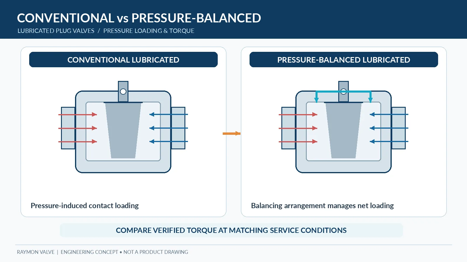
Both constructions use a rotating plug to provide the specified flow path and shutoff duty. The pressure-balancing feature is a load-management detail, not a separate proof of seat tightness, bidirectional sealing, fire-safe performance or suitability for a particular fluid. For a broader overview of product-family differences, see industrial plug valve configurations.
| Evaluation item | Conventional lubricated | Pressure-balanced lubricated |
|---|---|---|
| Pressure loading | Depends on pressure-exposed plug geometry, cavities and support arrangement. | Adds design-specific balancing provisions intended to manage net plug loads. |
| Axial contact / wedging | Unfavorable axial loading may increase tapered-plug seating contact. | May reduce selected axial loading components; no universal load reduction. |
| Breakaway torque | Must be validated for governing ΔP, temperature and idle condition. | Must still be validated under the same specified conditions. |
| Running / closing torque | Depends on friction, packing, sealant and flow/pressure state. | Same contributors remain; balancing does not remove all friction. |
| Sealing system | Injected sealant and approved service procedures typically remain central. | Injected sealant and approved service procedures may still be necessary. |
| Pipeline selection | Can be suitable with substantiated torque and sealing performance. | Worth evaluating when pressure-related loading is a material constraint. |
A valid bid comparison uses the same valve size, operating pressure differential, flow/pressure direction, temperature, sealant assumptions and duty cycle. A construction label without these conditions does not establish an operating advantage.
2. How Pressure Loading Acts on a Conventional Lubricated Plug Valve
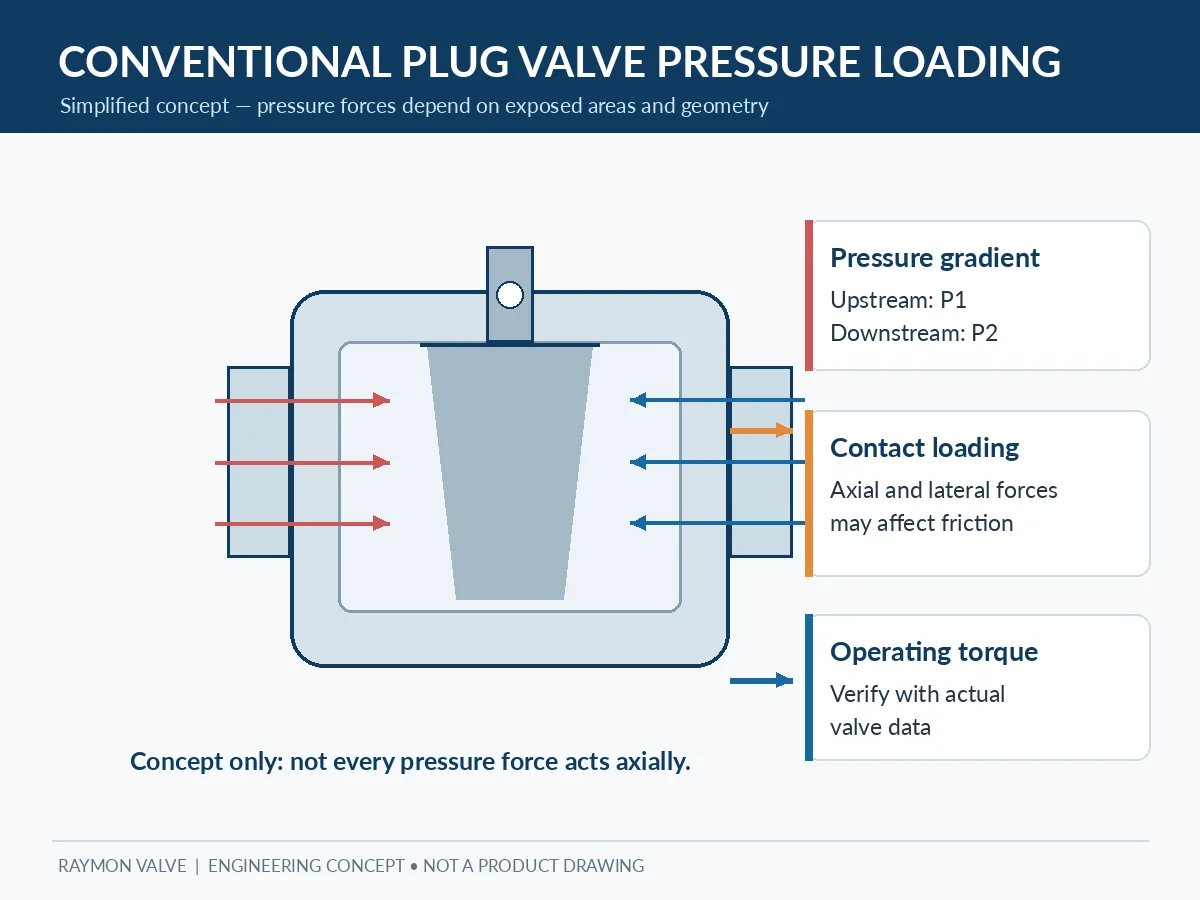
Pressure distribution and tapered-plug geometry
Pressure acts on the plug surfaces exposed to each communicating region. Its resultant depends on the projected areas, direction of loading, cavity pressure, plug position and mechanical support. A tapered plug can develop axial loading that changes contact pressure between the plug and body. Pressure can also create transverse loads; it would be incorrect to describe every pressure-induced force as purely axial.
Contact loading and breakaway friction
In a conventional arrangement, an unfavorable load can press the plug more firmly into its seating interface. Higher contact force may increase the friction contribution to the torque required to initiate rotation. Sealant condition, surface finish, deposits, packing friction and changes from thermal cycling also matter. The actual force and torque require manufacturer-specific design information.
Pressure rating is not operating differential pressure
The body pressure-temperature rating establishes a pressure-boundary envelope under the applicable rules. The differential pressure acting across the closure during opening or closing is a separate operating input. Two valves with the same class can require very different operating torque if one opens near equalized line pressure and the other must open against high differential pressure.
RFQ example — same class, different required torque: Two valves can carry the same pressure class while only one must open against the full upstream-to-downstream differential. The pressure rating describes the applicable pressure-boundary rating at temperature; it does not identify the differential pressure during operation. Action: specify the worst credible opening and closing pressure cases, including reverse direction where required, and compare torque on that basis.
The RFQ should identify the maximum differential pressure at which the valve must operate, including pressure direction and any credible trapped-cavity or reverse-pressure cases.
Practical load check: which pressure acts where?
For a specific valve, request a sectional pressure-boundary sketch for the fully closed position and for the operating position that produces the governing torque. Identify upstream pressure, downstream pressure, any trapped or communicating cavity pressure, the plug’s projected areas, and mechanical support forces. A simplified axial-force statement is net axial force = sum of signed pressure × projected-area terms + mechanical axial contributions. This is a bookkeeping concept only; it does not predict torque without contact-force distribution, friction behavior, geometry and validated manufacturer data.
3. How Pressure-Balanced Designs Manage Internal Forces
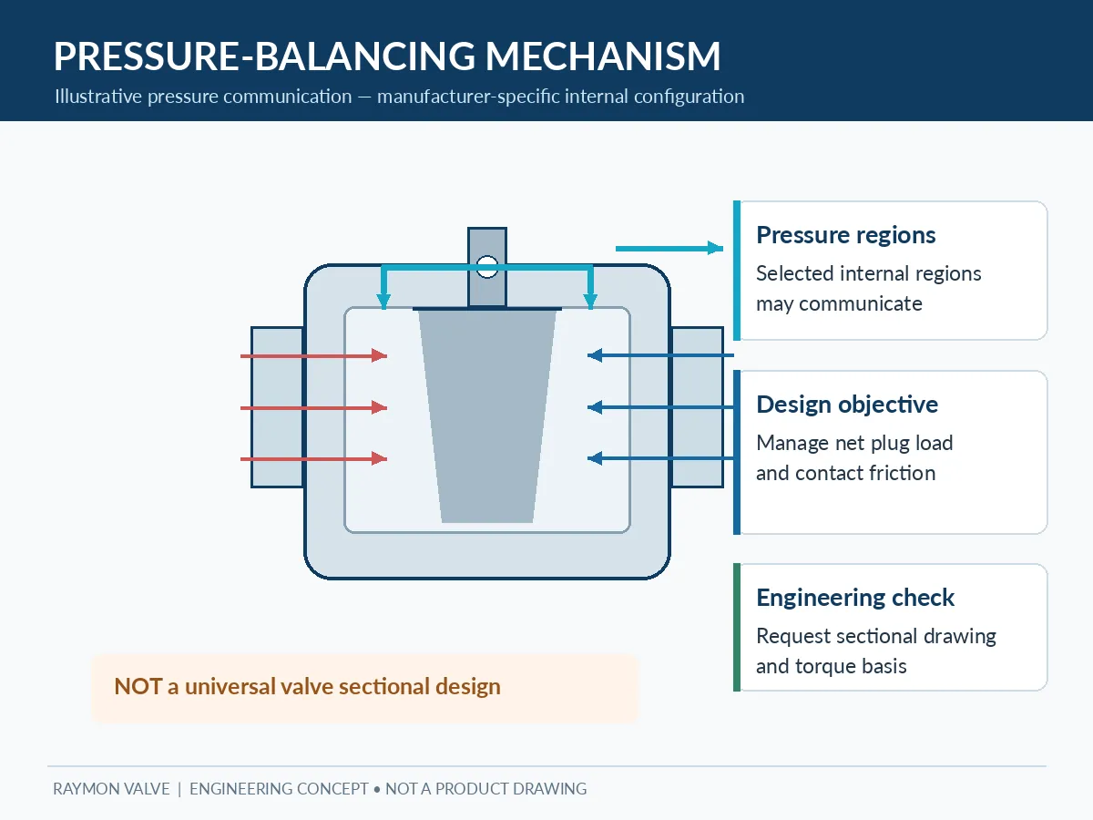
Interpretation limit: The conceptual arrows illustrate possible pressure communication; they do not establish which cavity is pressurized in every valve position, prove that balancing occurs in either pressure direction, or define a validated pressure path for a Raymon Valve model. Ask for the actual manufacturer sectional drawing and operating-pressure cases.
Pressure communication and net plug load
A pressure-balanced lubricated plug valve uses a defined internal arrangement to change how pressure acts on the plug. Depending on the design, passages, chambers or support features can alter net axial loading and the resulting contact friction. An illustrative force balance is the sum of pressure acting on signed projected areas plus mechanical contributions; it is not a universal pressure-balanced-valve sizing formula.
Force-balance boundary: Conceptually, the resultant force follows the vector sum of pressure acting over exposed projected areas together with mechanical supports and contact reactions. An improvement in one axial or seating-load component need not produce a proportional reduction in total stem torque; transverse loading, packing friction, sealant resistance and other contributors can remain dominant. The exact pressure path and response to reversal must be checked against the offered valve’s sectional drawing.
Construction-specific details
Some products use an inverted tapered plug; others use different balancing passages and mechanical retention features. A balancing passage must not be confused with a sealant-injection groove, and an internal balancing arrangement should not be confused with a bypass that equalizes upstream and downstream pipeline pressure.
For technical approval, request a sectional drawing showing plug orientation, support and retention, balancing passage locations, sealant injection paths and stem sealing.
What pressure balancing cannot establish
Pressure balancing does not automatically guarantee a fixed torque reduction, eliminate static friction, establish allowable leakage or demonstrate compliance with an application standard. It addresses only those load components the particular design is intended to manage.
Pressure-path verification before technical approval
Require the bidder to show whether the balancing route remains functional in the specified open, closed and intermediate positions, how the design responds to pressure reversal, and whether the process medium could obstruct the relevant passages. These are questions for the specific offered model—not general claims that every pressure-balanced plug valve behaves identically. A balancing path is not a line bypass or an automatic upstream/downstream equalizer.
4. Operating Torque: Breakaway, Running and Actuator Requirements
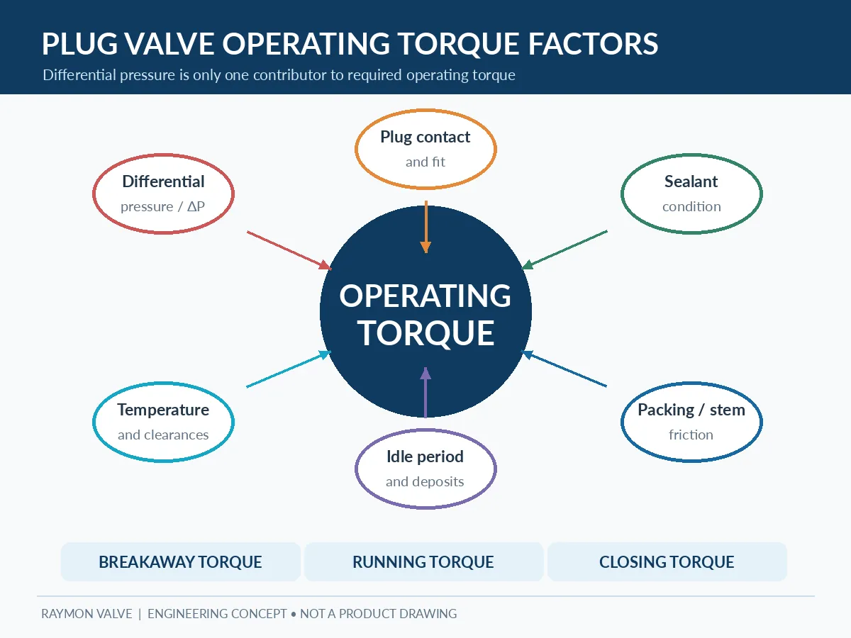
Pressure-load-to-torque boundary: A reduction in one pressure-induced axial or seating load component may reduce one friction contributor, but cannot be converted directly into an equal percentage reduction of total stem torque. Transverse contact reactions, packing friction, injected-sealant behavior, support friction and operating position may dominate particular cases. Compare complete torque envelopes, not inferred savings from force balance alone.
Breakaway, running and closing torque
Breakaway torque starts plug movement; running torque maintains movement; closing torque reflects the loads met during final closure. The peak requirement may occur at different positions for different designs and services. A single unspecified “operating torque” number is insufficient for critical actuator selection.
| Condition | Why it matters | Supplier evidence |
|---|---|---|
| Opening breakaway | Stationary friction and pressure-related loading may be highest at initiation. | Torque basis at governing ΔP and temperature. |
| Running / closing | Resistance can vary throughout the quarter-turn. | Torque-versus-position or justified maximum values. |
| Reverse pressure | Different pressure direction can change contact loading. | Directional torque and sealing scope. |
| Extended idle | Sealant changes, deposits and static friction can affect restart. | Specified idle-period assumptions. |
| Operator sizing | Gear efficiency, utility supply and required margin affect sizing. | Complete actuator/gear calculation and torque margin. |
Avoid universal torque-reduction claims
A published percentage reduction is meaningful only when the comparison basis is defined: equal valve geometry, pressure differential, operating direction, temperature, sealant condition and measurement method. Do not transfer a percentage from one manufacturer or valve series to another.
Actuator and manual-operator verification
For actuated packages, check maximum valve torque versus available operator output across travel at the least favorable supply condition, with required safety margin and stem capacity. Include cycle time, fail action and torque-transmission losses when relevant. For manual packages, verify gearbox, input force and access. Neither valve size nor pressure class alone can determine actuator size.
Minimum comparable torque-data basis
A torque number without its governing conditions cannot be used reliably to compare competing bids or size an actuator. Request the following information for each proposed construction.
Bid-review example — noncomparable torque figures: Supplier A quotes breakaway torque after a defined idle period at the maximum required operating differential pressure, while Supplier B quotes running torque at a lower differential pressure. The numbers cannot be ranked as alternatives. Action: request both opening and closing torque envelopes for the same pressure, temperature, direction and valve condition, together with the gearbox and actuator output basis.
| Parameter | Required reporting basis | Risk if omitted |
|---|---|---|
| Torque condition | Opening breakaway, running peak, closing and seating as relevant | Unclear maximum duty |
| Differential pressure | Magnitude, direction and timing of governing ΔP | Incomparable quotes |
| Fluid and temperature | Specified service medium, minimum/maximum relevant operating temperature | Invalid friction/packing assumption |
| Valve condition | Sealant type, prior operation, expected idle period and cleanliness assumption | Underestimated restart demand |
| Basis of evidence | Model-specific calculation, qualified test or documented engineering method, with limitations | Unsupported actuator selection |
| Actuator output | Minimum available utility conditions, gearbox effects, chosen margin and stem capacity | Insufficient deliverable torque |
Bid-normalization rule: compare the maximum required valve torque under the same specified operating cases before applying an agreed actuator margin. Do not subtract a generic pressure-balance percentage or infer a final actuator size from nominal pressure class.
5. Sealant Systems: What Changes and What Stays the Same?
Sealant film, grooves and injection access
Both conventional and pressure-balanced lubricated designs can rely on injected compound to support the sealing and sliding interface. The approved sealant, injection fittings, grooves, compatibility envelope and access requirements should be identified for the actual valve. Pressure balancing does not eliminate the sealing compound by definition. Review the lubricated plug valve product information as a product reference; obtain model-specific documentation before relying on any performance claims.
Injection pressure versus balancing pressure
Sealant-injection pressure delivers compound into its designated passages. Balancing pressure is process pressure distributed across specific plug surfaces. These are different functions. Manufacturer-defined service limits and isolation precautions must govern sealant injection; improvised high-pressure injection to overcome unexplained torque is inappropriate.
Compatibility and servicing
Review fluid composition, solvent exposure, temperature, solids, product cleanliness and allowable contamination before accepting a lubricated sealing system. Sealant replenishment intervals depend on service and vendor guidance; a balancing feature is not proof of longer service intervals. Fouling risk around balancing passages also requires construction-specific review where relevant.
Leakage or high torque after sealant servicing
If shutoff or operating torque deteriorates, do not assume additional injection will correct the problem. The cause may involve unsuitable compound, incorrect servicing, wear, deposits, blocked distribution features or mechanical damage. Isolate and depressurize only under the approved site procedure and use the manufacturer’s maintenance instructions; do not force operation or exceed specified injection limits.
Maintenance example — rising torque after a long shutdown: Increased breakaway resistance may reflect aged or incompatible sealant, deposits, packing friction, corrosion or unfavorable plug loading. Pressure balancing is not a universal corrective measure. Action: record the symptom and operating history, isolate and depressurize under the site’s approved procedure before intrusive maintenance, and seek the manufacturer’s diagnosis if the required torque exceeds the approved limit. Do not force the stem or apply improvised sealant-injection pressure.
6. Pipeline Selection: When Is Pressure Balancing Worth Considering?
Selection boundary: High differential pressure, large nominal size, infrequent operation or restricted operator space are screening triggers, not pass/fail thresholds or automatic reasons to reject conventional construction. Confirm each bidder’s allowable opening and closing differential pressure, actual torque, pressure direction, sealant requirements and operator capacity before choosing.
When to evaluate pressure-balanced construction
Pressure-balanced construction deserves particular attention when the specified opening differential pressure creates significant plug-loading or operating-torque concerns, a manual gearbox is constrained, remote actuation is required or the valve will remain stationary for prolonged periods. Those conditions justify comparison, not an automatic selection.
When conventional lubricated construction remains viable
A conventional lubricated valve may remain appropriate when the manufacturer verifies the required pressure-temperature envelope, differential-pressure duty, shutoff performance, torque, sealant compatibility and servicing. Do not exclude conventional construction merely because a project is described as “high pressure.”
Special conditions requiring review
- Solids, sludge and fouling that could affect the sealing interface or pressure-communication passages.
- Corrosive fluids requiring checks of all wetted components and approved sealing compound.
- Thermal cycling or low-temperature duty that changes clearances and sealant behavior.
- Fire-safe, fugitive-emission or safety-related actuation needs requiring separate evidence.
- Continuous throttling, where port geometry, velocity and erosion require a different duty review.
Service risk and supplier-verification matrix
| Observed or anticipated issue | Possible contributors, not diagnosis | Evidence to request |
|---|---|---|
| High opening breakaway torque | Pressure-related contact load, long idle period, packing, deposits or sealant condition | Torque-vs-ΔP basis, idle assumptions, maintenance history and sectional drawing |
| Torque differs after pressure reversal | Asymmetric loading, cavity communication or seating response | Bidirectional operating torque and pressure-path evidence |
| Torque increases after thermal cycling | Expansion, packing preload or sealing-compound changes | Specified temperature-dependent torque case |
| Uncertain balancing function in fouling service | Obstruction of passages or deposits in contacting regions | Passage layout, contaminant limits and maintenance provisions |
| Leakage after extended service | Sealant degradation, wear, surface damage or service mismatch | Leakage test basis and approved servicing procedure |
7. Applicable Standards, Testing and Technical Documentation
Standards must be specified by their applicable scope and project-agreed editions. They cannot replace model-specific confirmation of pressure balancing, sealing or actuator torque. Review the industrial valve standards resource and valve pressure-testing overview as background, while relying on the governing purchase specification for acceptance.
| Reference | Purpose in this article | What it does not prove |
|---|---|---|
| API 599 (where applicable) | Metal plug-valve product requirements within its defined scope. | A fixed pressure-balancing torque reduction. |
| API 6D (where applicable) | Pipeline/piping valve product and purchaser requirements within scope. | Automatic suitability of every plug-valve configuration. |
| ASME B16.34 (where applicable) | Pressure-temperature and relevant valve design/rating requirements. | Allowable operating ΔP or torque for a specific model. |
| API 598 / agreed test standard | Inspection and pressure/closure testing when specified. | Operating-torque performance under all service conditions. |
The supplier should provide an approved datasheet and GA/sectional drawings, material records, approved sealant specification, operating-torque basis, actuator calculation where needed, inspection and test plan, test records and operation/maintenance manual. Shell tests, closure tests, functional checks and torque tests establish different characteristics and are not interchangeable.
Edition and scope control: The API Standards Plan lists API 599, Ninth Edition (October 10, 2025), for metal plug valves and API 598, Eleventh Edition (February 8, 2023), for valve inspection and testing. The API 6D latest updates identify the 25th Edition with Addendum 3 (March 2025). ASME B16.34-2025 addresses valves within its stated construction and material scope, including pressure-temperature ratings. Agree the governing edition and any addenda in the purchase specification. A product or inspection standard does not independently establish allowable operating differential pressure, verified actuator torque or a guaranteed pressure-balancing advantage for a particular model.
Official reference: API Standards Plan. As one design-specific illustration rather than cross-brand proof, Flowserve’s Dynamic Balance product documentation explicitly links its stated operating behavior to its own balancing construction and sealant distribution design.
8. Pressure-Balanced vs Conventional Selection Matrix
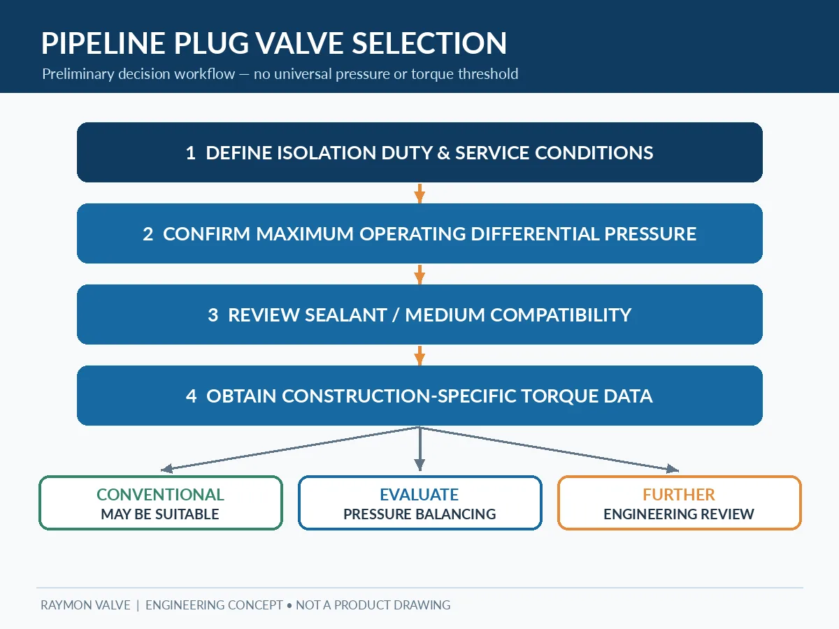
The decision table is a preliminary screening tool, not a substitute for a certified datasheet.
| Service scenario | Initial comparison direction | Evidence needed |
|---|---|---|
| Moderate ΔP with acceptable verified torque | Conventional lubricated may be sufficient. | Torque and shutoff records. |
| High governing operating ΔP / seating-load concern | Evaluate pressure-balanced and conventional options. | Actual balancing design and operating torque. |
| Large size and restricted operator effort | Compare complete valve + operator packages. | Stem, gearbox and torque envelope. |
| Extended idle or infrequent operation | Evaluate restart assumptions for both. | Sealant, idle period and breakaway basis. |
| Fouling or abrasive service | No default winner. | Flow path, passages, materials and maintenance. |
| Process contamination restrictions | Reconsider lubricated sealing route. | Acceptability of injected sealant. |
| Remote or safety-related actuation | Project-specific operator review. | Torque, utility and required fail behavior. |
Decision sequence: define isolation duty → establish maximum operating differential pressure and direction → confirm sealant acceptability → review pressure-loading arrangement → obtain manufacturer torque basis → verify operator package → agree tests and documents.
9. Plug Valve RFQ Checklist and Bid Normalization
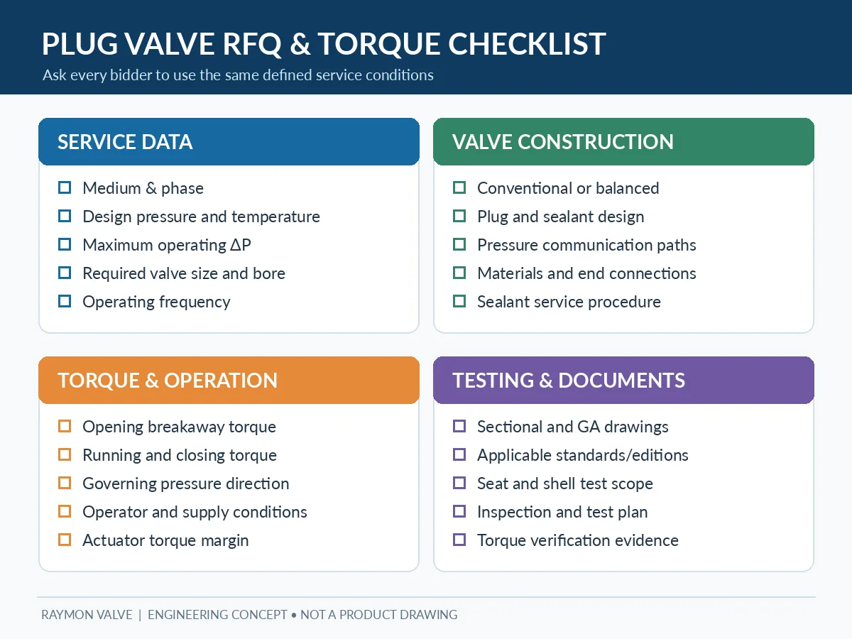
Missing torque assumptions can make two quotations appear comparable even when their operating duty is different. Use the same conditions for each bidder and request documentation for the actual offered construction.
| RFQ input | Buyer should specify |
|---|---|
| Process conditions | Fluid/composition, solids, phase, normal/design pressure and temperature. |
| Operating load | Maximum opening/closing ΔP, pressure direction and credible abnormal cases. |
| Valve construction | NPS/DN, bore, class/PN, ends, plug configuration and materials. |
| Sealing | Shutoff/leakage acceptance, approved sealant and servicing access. |
| Operation | Frequency, idle period, manual/gear/pneumatic/electric/hydraulic package. |
| Torque evidence | Opening breakaway, running and closing conditions, basis and margin. |
| Verification | Applicable standard editions, inspection/test plan, records and deviations. |
Pressure-balancing evidence to request
- Sectional drawing identifying balancing regions, plug support and sealant passages.
- Maximum operating differential pressure and torque in each required pressure direction.
- Sealant grade, injection procedure and process compatibility confirmation.
- Opening, running and closing torque under the governing scenario.
- Operator calculation with minimum available supply, applicable margin and stem capacity.
- Test procedure, acceptance criteria, material traceability and list of technical deviations.
Technical bid normalization before purchase approval
| Offer comparison | Supplier A / conventional | Supplier B / pressure-balanced | Buyer decision gate |
|---|---|---|---|
| Maximum opening/closing ΔP | To be stated | To be stated | Same operating case and direction? |
| Breakaway / running / closing torque | To be evidenced | To be evidenced | Same temperature, fluid and idle assumption? |
| Operator package | Include full scope | Include full scope | Margin and minimum utility output confirmed? |
| Sealant / maintenance | Document servicing | Document servicing | Compatible and accessible? |
| Inspection and documents | Include agreed ITP | Include agreed ITP | Same deliverables and deviations? |
Purchase hold point: do not accept either construction solely on claims of easier operation. Close unresolved torque, leakage, sealant and documentation deviations before technical approval.
10. Frequently Asked Questions
What is the main difference between pressure-balanced and conventional lubricated plug valves?
They differ in how pressure-induced forces acting on the plug are managed. Pressure-balanced construction adds a design-specific arrangement intended to control unfavorable loading; both require separate sealing, torque and service verification.
Does a pressure-balanced plug valve always require less operating torque?
No. Balancing may reduce some load-related friction, but packing, sealant, deposits, temperature and other factors still influence torque. Compare vendor data under equivalent duty.
How does differential pressure affect lubricated plug valve operation?
Differential pressure changes forces on pressure-exposed plug surfaces and can alter contact friction. The actual effect depends on geometry, cavity pressure and support; the maximum operating ΔP must be stated separately from class.
Do pressure-balanced lubricated plug valves still require sealant injection?
Many designs still use an approved sealant injection system. Pressure balancing addresses process-pressure loading; sealant injection supports the sealing interface. Maintenance must follow model-specific instructions.
When should pressure-balanced construction be considered for pipeline isolation?
Consider it when verified operating ΔP, operator limitations or long idle periods create important pressure-loading concerns. Final selection needs vendor-specific torque, sealing, material and documentation review.
Conclusion: Select by Pressure Loading and Verified Torque
Pressure-balanced construction is valuable when its specific design helps control the loading that limits operation. It is not universally preferable to a conventional lubricated valve. Confirm the actual duty, sealant compatibility, operating torque, actuator requirements and supplier evidence before choosing the construction. Buyers evaluating other sealing architectures can separately review industrial plug valve configurations and the lubricated plug valve product information.
Product-page evidence note: Product-family pages are navigation aids, not a substitute for a model-specific sectional drawing, torque report or approved compliance documentation.
Request a Plug Valve Torque & Pressure-Balancing Review
Share the process fluid, valve size, design and operating pressure/temperature, maximum opening and closing differential pressure in each required direction, sealing criteria, operating frequency/idle period, preferred operator or actuator and test requirements. Request construction-specific balancing details and torque evidence for the offered valve.
Submit Your Valve Datasheet for Technical ReviewEngineering note: These are preliminary selection considerations. Actual suitability, torque, balancing arrangement, applicable standards and documentation must be verified for the offered valve and project.
 English
 German
 Arabic
 French
 Spanish
 Italian
 Portuguese
 Russian