
Control Valve Engineering · Trim Selection
Balanced control valve trim reduces the net static pressure force on the plug; unbalanced trim generally carries a greater pressure-induced load under comparable conditions. This difference can change actuator thrust requirements and the maximum shutoff differential pressure the assembled valve can handle. It does not by itself determine seat leakage or control accuracy. Choose between the designs by reviewing the plug and balance-seal arrangement, shutoff class, governing pressure cases, fluid and temperature limits, and verified actuator output. The comparison and RFQ checks below show what to request from suppliers.
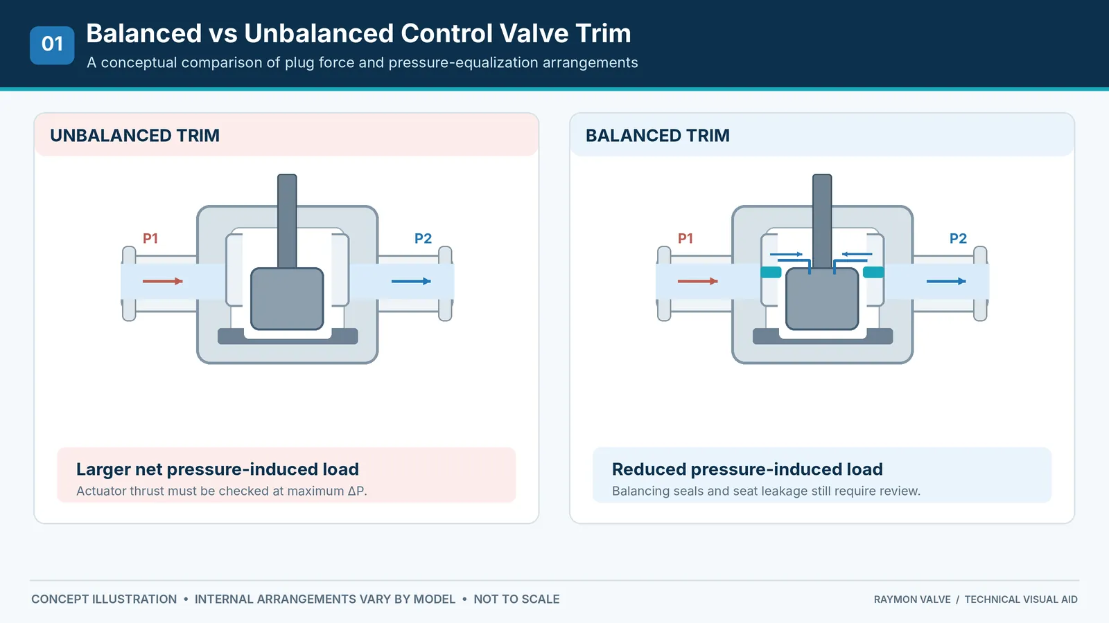
Balanced vs Unbalanced Control Valve Trim: Key Differences
The key distinction is pressure-force management, not an automatic difference in quality, controllability or shutoff class. Buyers comparing control valves should check the entire assembly rather than choosing from the trim label alone.
| Comparison factor | Balanced trim | Unbalanced trim |
|---|---|---|
| Pressure force | Opposing pressure areas reduce the net static plug force. | Often experiences a larger net static plug force. |
| Actuator thrust | May reduce the force needed to overcome differential pressure. | May demand higher thrust for a large effective unbalanced area or high ΔP. |
| High shutoff differential pressure | Often worth evaluating, subject to actual seat and seal capability. | May require a larger actuator or another construction. |
| Seat leakage | Depends on seat, balance seal and complete-valve test results. | Depends on seat design, load, materials and test results. |
| Dynamic friction | Balancing seals may introduce additional friction. | No equivalent balance-seal friction in designs without a balance seal. |
| Maintenance | Inspect balance seals and pressure-equalization features where fitted. | Inspect seats, guides, packing and other model-specific wear points. |
How Balanced and Unbalanced Control Valve Trim Works
Unbalanced Trim: Pressure Force Acting on the Plug
In unbalanced trim, upstream and downstream pressures act on plug surfaces and create a net pressure-induced force. The direction and magnitude depend on valve geometry, the effective pressure-exposed area, pressure distribution and flow orientation. This force can assist or oppose the actuator, depending on the specified operating case.
An unbalanced construction can still be an appropriate choice when the actuator is capable of meeting the operating and shutoff loads and the seat design satisfies the leakage requirement. Simpler internal sealing arrangements may be attractive, but they should not be assumed for every unbalanced model.
Balanced Trim: Pressure Equalization and Sealing Elements
A pressure-balanced plug uses a pressure-equalization arrangement so that pressure acts on opposing effective areas, reducing the net static load. Common designs may include passages and a balancing seal between the plug and surrounding structure. The actual geometry and sealing method vary by manufacturer and model.
Pressure balance reduces one component of actuator demand; it does not cancel flow forces, seat loading, stem friction or balancing-seal friction. It may also introduce internal leakage paths or service limitations that must be assessed independently.
Why Cage-Guided Does Not Automatically Mean Pressure-Balanced
Cage-guided identifies an internal guiding and trim arrangement. It does not, by itself, confirm whether the plug is pressure-balanced. A cage-guided control valve can incorporate different pressure-force and sealing arrangements. Review the actual sectional drawing, plug passages and balance-seal details before classifying the offered trim.
How Differential Pressure Affects Actuator Thrust
Pressure Differential and Effective Unbalanced Area
The simplified relationship below explains the static pressure-force component for an idealized plug area:
Here, ΔP represents the relevant pressure difference and Aeffective is the net effective unbalanced area projected in the direction of plug travel. For an actual plug, pressure acts on different surfaces and the axial resultant depends on their geometry and pressure distribution; the direction of the force may reverse between operating cases. This simplified expression is not the final actuator-sizing equation. Fluid-dynamic forces, seat load, packing friction, balance-seal friction and available actuator output must be evaluated for the actual construction.
Do Not Confuse Operating Pressure Drop With Shutoff Differential Pressure
Actuator review should cover the specified normal operating ΔP, the maximum operating ΔP and the maximum shutoff ΔP. These values may occur at different flow and valve positions. A valve that modulates acceptably under normal conditions can encounter its governing load during closing, opening or a required failure condition.
Illustrative engineering check — shutoff case: A valve may throttle at a modest normal pressure drop while the closed valve is required to hold a much higher upstream pressure during a blocked-outlet condition. If the RFQ only shows normal running ΔP, one bidder may size the actuator for the wrong load case. Compare the process pressure-case schedule with the specified maximum shutoff differential pressure, then request opening, closing and seating force calculations for the offered trim at the minimum available supply.
Flow-to-Open, Flow-to-Close and Seating Force
Flow direction changes how pressure and dynamic fluid forces act on the plug. Depending on the design, the forces may assist or resist valve movement. Required seat load and leakage criteria also influence the closing case. Do not assume all flow-to-close designs share the same force sign or that every balanced plug has negligible operating force.
Friction, Supply Pressure and Fail Action
The actuator must provide adequate output throughout the required stroke and at the minimum available supply condition. For spring-return pneumatic actuators, spring characteristics and fail action can materially alter available thrust. Packing, guiding and balance-seal friction must be assessed under relevant pressure and temperature conditions. For a separate review of utility requirements and failure behavior, see pneumatic vs electric actuator selection; either approach still requires model-specific force verification.
Illustrative actuator check — utility margin: A supplier may quote actuator thrust at nominal plant-air pressure although the project specifies a lower guaranteed minimum at the valve. The package can appear adequate on paper yet lack force at the governing seating or spring-return condition. Normalize bids at the guaranteed minimum supply, review the complete force-versus-travel information and confirm accessories and failure action in the assembled package.
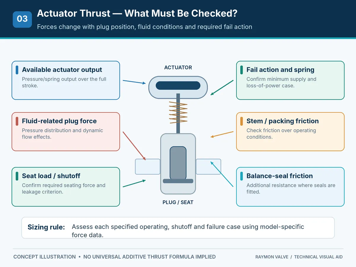
Actuator Review: Identify the Governing Pressure and Failure Cases
A supplier should show how the offered actuator handles the limiting case, which may not be the same at every plug position. At minimum, align the valve, actuator and project teams on the conditions below. Include the direction of the force and the minimum available driving energy rather than reporting a single peak-thrust number.
| Case to evaluate | Why it can govern | Minimum evidence in the offer |
|---|---|---|
| Normal modulating range | Flow force, packing friction and positioner response can influence controllability even if static pressure force is small. | Relevant flow/pressure cases and any performance assumptions. |
| Maximum operating differential pressure | The greatest differential pressure during required travel may occur away from normal flow. | Direction of travel, pressure-force model and actuator output along the stroke. |
| Maximum specified shutoff differential pressure | Closing or holding the plug on the seat may require a different net force from modulating operation. | Seat-load requirement, leakage criterion, force balance and available closing thrust. |
| Loss of supply / specified fail action | The spring-return or stored-energy case may have less available force than powered operation. | Fail direction, minimum supply assumptions, spring range and demonstrated travel/seating capability. |
For reversing or bidirectional differential-pressure conditions, the manufacturer should assess each required direction. A calculation that proves movement in one direction is not automatically evidence for the opposite case.
Balanced vs Unbalanced Trim: Seat Leakage and Shutoff Performance
Seat Leakage, Balancing-Seal Bypass and Stem Packing Leakage Are Different
Seat leakage refers to flow across the closed plug-and-seat interface. Balancing-seal bypass is internal flow past a balance seal in designs that contain such a seal. Stem packing leakage is escape from the pressure boundary toward atmosphere. These are distinct paths and may be assessed using different requirements.
Internal balancing-seal bypass can contribute to total closed-valve leakage in some arrangements, but not all pressure-balanced trims have the same sealing layout. The buyer should request confirmation of the complete offered valve design rather than assuming the seat interface alone determines shutoff performance. Ask for a model-specific sectional drawing that identifies which internal cavities can communicate across the closed valve and whether any balancing-seal bypass is part of the specified seat-leakage acceptance boundary.
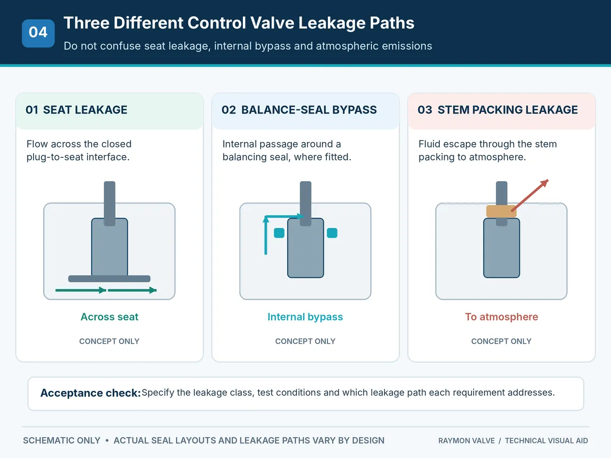
Can Balanced Trim Meet Class V or Class VI?
There is no valid universal rule that all balanced trim fails to achieve Class V or Class VI, or that all unbalanced trim automatically achieves tighter shutoff. Leakage capability depends on the seat design, pressure direction, loading, materials, balancing-seal arrangement and the tested valve assembly. Some constructions can be engineered for demanding leakage requirements, but the result must be demonstrated for the offered model.
Illustrative bid comparison — leakage: Two quotations may both state “Class V” while one references a bare seat design and the other documents a complete pressure-balanced valve with its installed balancing seal. The label alone does not make the offers equivalent. Require the same applicable leakage standard, pressure direction, test differential pressure, medium and offered trim configuration, and resolve any deviation before technical approval.
Define the required class and test conditions under the applicable project specification. ANSI/FCI 70-2-2021 addresses control-valve seat leakage testing; it does not promise zero leakage under all process conditions. IEC 60534-4:2021 covers inspection and routine testing within its published scope.
What a Seat-Leakage Test Does—and Does Not—Demonstrate
To normalize supplier claims, identify the complete tested assembly and test boundary. The requested record should state the test method, declared class, test medium, pressure differential and direction, applicable seating/actuation conditions and acceptance result. Confirm whether the offered balance-seal configuration was included in that test.
Meeting a specified seat-leakage test is evidence of performance under the documented test conditions; it is not proof that field leakage will remain identical at every service temperature, medium composition or differential pressure. A generic seat specification, a catalogue label or a test certificate for a different construction should not be substituted for the agreed acceptance evidence.
Fail-Close Does Not Automatically Mean Tight Shutoff
Fail-close specifies the intended failure position. Tight shutoff requires a separately defined acceptance criterion and proof that the complete valve and actuator assembly can develop the necessary seat load in the applicable conditions. Record both requirements in the RFQ.
Control Accuracy, Friction and Maintenance Considerations
Friction and Modulating Response
Balanced trim can reduce pressure-induced plug force while introducing balance-seal friction. Both balanced and unbalanced designs remain sensitive to packing friction, guiding, actuator selection, positioner setup and process conditions. No trim type should be described as inherently more accurate without relevant response data.
Balance-Seal Wear and Temperature Effects
Dynamic seals and clearances may change behavior with operating temperature, thermal expansion, wear and process fluid compatibility. Request model-specific limits for the proposed seat and balancing-seal materials, especially in high-temperature or repeated-cycling duties.
Contamination, Fouling and Maintenance Access
Particles, deposits, crystallization and polymerization can interfere with pressure-equalization passages, guiding clearances or sealing faces. This does not make all balanced trim unsuitable for dirty media, nor does it make unbalanced trim automatically suitable. Compare the actual passage sizes, seal arrangement, expected solids loading and maintenance method. Neither construction should be presented as maintenance-free.
Illustrative service review — fouling: For a crystallizing or particle-bearing liquid, a pressure-balancing passage or moving seal can become an additional maintenance concern even when the calculated actuator load is favorable. Ask for a sectional drawing identifying minimum clearances and wetted seals, review the medium at start-up and shutdown temperatures, and agree on cleaning access and spares before accepting the construction. An unbalanced alternative still requires its own erosion, flow-force and seat-wear assessment.
Failure Mode and Maintenance Verification Matrix
Use the following symptom-to-evidence checks when evaluating a proposal or preparing a maintenance plan. They identify investigation priorities, not a diagnosis or instructions to operate a damaged valve.
| Observed concern | Potential contributors | Evidence or follow-up |
|---|---|---|
| Higher-than-expected closing leakage | Seat damage, inadequate seat loading, balance-seal bypass in applicable designs or off-design test conditions. | Leakage test result, test conditions, trim drawing, seat and balance-seal condition. |
| Sluggish response / deadband | Packing friction, balancing-seal friction, guide wear, actuator/positioner setup or changing process loads. | Travel trends, instrument-air checks and documented friction/actuator assumptions. |
| Sticking after temperature change | Thermal clearances, seal expansion, deposits or material incompatibility. | Verified temperature limits, material data and manufacturer inspection instructions. |
| Recurring seal wear or fouling | Solids, abrasion, polymerization, deposits or incompatible seals. | Medium analysis, particle/deposit description, passage dimensions and spare-part plan. |
Safety boundary: Plant troubleshooting, disassembly and testing must follow the site’s isolation, depressurization and maintenance procedures. Escalate unexpected leakage or actuator force deficiency to the responsible engineering team and equipment manufacturer.
When Should You Choose Balanced or Unbalanced Control Valve Trim?
High Differential Pressure Services
Evaluate balanced trim when the calculated pressure-induced plug load makes actuator sizing or shutoff capability difficult. Simultaneously assess high pressure-drop phenomena such as noise, cavitation, flashing and erosion where applicable. Pressure balance is not a substitute for appropriate flow-path design.
Tight Shutoff and Low-Leakage Applications
Start with the required leakage criterion, not the trim label. Unbalanced trim may be attractive when its construction avoids an additional balancing-seal bypass, while a suitable balanced design may also satisfy stringent leakage requirements if supported by evidence.
Steam, Gas, Clean Liquid and Fouling Media
Medium names alone do not select trim. Clean steam or gas may call for temperature, noise and high-ΔP review; liquids may raise cavitation or flashing concerns; contaminated fluids require assessment of solids, narrow passages, wear and maintenance. Consider material compatibility and full operating conditions for each proposed construction.
High-Temperature and Severe Service
Confirm thermal expansion behavior, seal materials, friction, seat loading and leakage performance at the relevant temperature and pressure. If special low-noise, anti-cavitation or erosion-resistant trim is needed, evaluate that requirement separately from plug pressure balance.
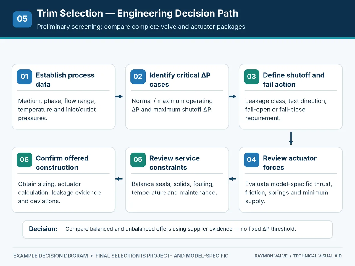
Balanced vs Unbalanced Trim Selection Matrix
The following matrix is intended for initial technical screening and RFQ normalization, not as a replacement for valve sizing or supplier calculations. It assumes comparable valve duties and defined shutoff conditions; no fixed differential-pressure threshold can determine the correct trim independently of plug diameter, effective area and actuator output.
| Service condition | Preliminary selection direction | Evidence to obtain |
|---|---|---|
| High maximum shutoff ΔP | Evaluate pressure-balanced trim. | Plug-force calculation, actuator output and shutoff capability. |
| Limited pneumatic supply | Compare force requirements of both designs. | Minimum air pressure, spring data and full-stroke available thrust. |
| Strict leakage requirement | Choose according to verified complete-valve performance. | Leakage class, test method, differential pressure and seal design. |
| Frequent modulating duty | Either, depending on dynamic response. | Seal friction, positioner response and wear considerations. |
| Dirty or fouling process | Construction-dependent engineering review. | Passages, clearance, solids, deposits and cleaning plan. |
| High-temperature service | Review materials and thermal effects for either. | Seat/balance-seal limitations and force at operating temperature. |
| Cavitation, flashing or severe noise | Separate severe-service trim evaluation. | Flow-capacity calculation, pressure recovery and mitigation approach. |
| External leakage or fugitive-emission requirement | Review stem/bonnet sealing separately from seat leakage. | Applicable stem-seal specification, offered packing construction and specified evidence. |
RFQ Checklist: What to Specify Before Selecting Control Valve Trim
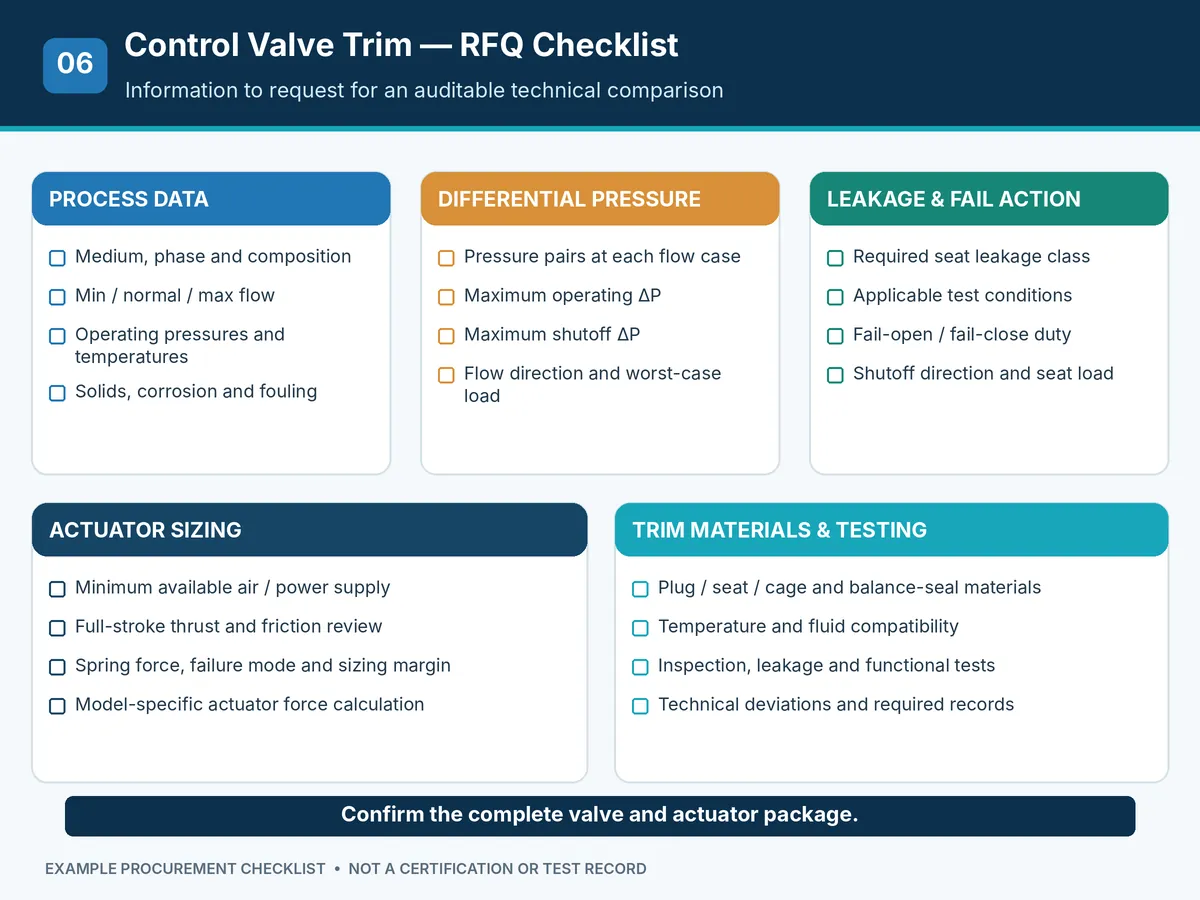
Comparable quotations require suppliers to use the same process cases and acceptance criteria. A general valve description is not enough to approve the trim or actuator. State the valve function, upstream/downstream piping conditions, allowable installation envelope and control objective in addition to the shutoff requirement.
Process and Differential Pressure Data
- Fluid composition, phase, density and other relevant properties.
- Minimum, normal and maximum flow with corresponding inlet/outlet pressures.
- Operating and design temperatures; maximum specified shutoff ΔP.
- Solids, erosion, corrosion, cavitation, flashing or fouling concerns.
Leakage, Fail Action and Actuator Requirements
- Required leakage class, applicable standard, test medium and conditions.
- Fail-open, fail-close or other specified failure position and expected closing load.
- Actuator type, minimum air/electric/hydraulic supply and full-stroke force basis.
- Required seat load, relevant friction assumptions, accessories and operating time.
Trim, Inspection and Bid Normalization
- Plug, cage, seat, packing and balancing-seal construction and materials.
- Supplier valve-sizing and actuator-sizing calculations for governing cases.
- Applicable leakage test, inspection plan and material documentation.
- List of deviations, exclusions, spare parts and unresolved design assumptions.
- Dimensioned or sectional trim drawing identifying pressure-equalization passages, balance seals and seat sealing surfaces.
- Clarification of whether quoted leakage applies to the complete supplied valve under the stated test conditions.
The supplier should confirm the complete valve and actuator assembly against the project specification and explain any unavailable or substituted information.
Supplier Technical Bid Comparison: Six Approval Gates
When two vendors propose different trim constructions, compare the same design cases and acceptance criteria before comparing actuator size, price or delivery. The table below can serve as an EPC technical-bid clarification checklist.
| Approval gate | What to request | Hold point / unresolved condition |
|---|---|---|
| 1. Process duty | Common minimum/normal/maximum process cases, fluid state and design temperature. | Vendors use different pressure/flow assumptions or omit a governing case. |
| 2. Trim construction | Sectional drawing; balanced/unbalanced classification; seat, cage and balance-seal arrangement. | Balance-seal design or internal bypass path is unspecified. |
| 3. Actuator capability | Force calculation for governing opening, closing, seating and fail-action cases at minimum available supply. | Only nominal actuator size or idealized supply pressure is provided; full-stroke output, mounting/access limitations or required accessories are omitted. |
| 4. Shutoff acceptance | Required leakage class, test method and test conditions for the offered assembly. | Claimed leakage class has no applicable model/design evidence. |
| 5. Materials and maintenance | Plug, seat, packing and balancing-seal materials; operating limits, service access, seal/seat replacement method, spare-part scope and estimated spare-part lead time (subject to supplier confirmation). | Temperature, fouling or compatibility assumptions are unresolved. |
| 6. Documentation and deviations | Calculation package, inspection/test plan, required material records, IOM documentation, technical deviations, accessory scope and exclusions. | Unaccepted deviations or test/document gaps remain before purchase-order approval. |
Compare the installed package and ownership scope—not only purchase price. For each offer, record actuator envelope and available installation/maintenance clearance, auxiliary air or electrical requirements, positioner and accessory inclusions, access needed to replace balancing seals or trim, recommended spares, IOM availability and spare-part supply assumptions. Maintenance intervals and lifecycle costs must be taken from supplier evidence or a stated project assumption; do not invent expected service life or savings.
Model-specific evidence request: Ask for the offered trim sectional drawing and revision, valve sizing results for governing cases, the actuator force/output basis at minimum supply, complete-valve leakage acceptance and applicable test records, and a clearly marked deviation schedule. A generic catalog, a certificate for another model or a schematic on this page cannot substitute for these deliverables. For broader procurement evidence gates, see the valve manufacturing and verification process resource; it is a process reference, not proof of this offered model.
Standards, Leakage Testing and Engineering Verification
Valve sizing, actuator force and leakage acceptance are separate engineering checks. A stated Cv/Kv or nominal size does not independently prove controllability across the required travel range or sufficient actuator thrust. A seat-leakage test does not prove the pressure-containing boundary, stem-emission performance or process suitability; those require their own defined evidence and acceptance criteria.
| Reference | Relevant purpose | Does not prove on its own |
|---|---|---|
| ANSI/FCI 70-2-2021 | Control-valve seat leakage testing. | Actuator sizing or universal process suitability. |
| IEC 60534-4:2021 | Inspection and routine testing for control valves within the specified scope; actuator requirements apply only to pneumatic actuators. | Electric or hydraulic actuator sizing, tests outside its scope, or hazardous-service qualification. |
| IEC 60534-2-1:2011 | Flow-capacity sizing equations for compressible and incompressible flow under installed conditions; the stated incompressible-flow equations are not intended for slurries, non-Newtonian fluids or liquid-solid conveyance systems. | Final actuator thrust, shutoff performance or applicability beyond the specified fluid model. |
| Model-specific manufacturer calculations | Plug-force cases, actuator output and construction limits. | Independent test acceptance unless supported by the specified records. |
| ISA75.24 technical committee | Industry work addressing forces on control-valve closure parts and actuators; relevant to the actuator-sizing evidence review. | Conformance to a published actuator-sizing standard or a model-specific force calculation. |
For further background, consult the Raymon Valve Knowledge Center and the site’s valve pressure testing resource. Project requirements and current standard applicability take precedence over general articles.
For IEC 60534-4:2021, the published scope includes control valves with pressure ratings not exceeding Class 2500, and it excludes certain hazardous applications such as fire safety testing and radioactive service. A project-specific hazardous-service specification may therefore require separate or overriding tests. The ISA75.24 committee describes ongoing technical work on forces and actuator sizing; its committee scope is not itself a certificate or a substitute for a supplier calculation.
External Technical References
- Fluid Controls Institute — ANSI/FCI 70-2 control-valve seat leakage standard listing.
- IEC 60534-4:2021 — Industrial-process control valves, inspection and routine testing.
- IEC 60534-2-1:2011 — Flow capacity and sizing equations under installed conditions (subject to fluid-model scope restrictions).
- Emerson Control Valve Handbook — control-valve construction, actuators and application background.
- ISA75.24 — Control Valve Actuator Sizing and Selection committee scope (technical background, not an implied product certification).
Frequently Asked Questions
What is the main difference between balanced and unbalanced control valve trim?
Balanced trim reduces net static pressure force by equalizing pressure across opposing effective plug areas. Unbalanced trim generally experiences a larger net pressure-induced force under comparable conditions. Seat leakage and overall suitability still depend on the actual valve design.
Does balanced trim always require a smaller actuator?
No. Balanced trim may reduce the fluid-force component, but final sizing also depends on packing and balance-seal friction, flow forces, seat load, actuator springs, minimum supply pressure and required fail action.
Can balanced control valve trim achieve Class V or Class VI shutoff?
That depends on the offered construction and verified test performance. The specified leakage class, test conditions, seat design and any balancing-seal bypass path must be reviewed together.
Is unbalanced trim better for tight shutoff applications?
Not universally. Some unbalanced designs avoid a balancing-seal bypass path, but actual shutoff performance depends on seat design, loading, materials, pressure conditions and the specified leakage test.
How does differential pressure affect control valve actuator thrust?
Differential pressure produces a net force over the effective unbalanced area. Balanced trim reduces that component, but an actuator calculation must also consider force direction, fluid forces, friction and seating requirements.
What data are required to select balanced or unbalanced trim?
Provide the medium, full flow and pressure cases, temperature, maximum shutoff differential pressure, leakage class, material limits, operating direction, minimum actuator supply and fail action. The supplier should confirm the complete valve and actuator package.
Final Selection: Review the Complete Valve and Actuator Package
Balanced trim is useful to evaluate when pressure-induced plug force is a major actuator-sizing constraint. Unbalanced trim may be appropriate where the calculated force, sealing arrangement and maintenance requirements suit the service. Neither option can be approved solely from a typical pressure differential, valve size or leakage-class label.
Before purchasing, require the supplier to document the governing pressure and force cases, applicable leakage acceptance, material and seal limitations, and the selected actuator’s available output. Final selection depends on the complete datasheet, applicable project requirements and model-specific evidence.
Request Control Valve Trim & Actuator Review
Describe your control-valve duty, minimum/normal/maximum flow cases with corresponding inlet and outlet pressures, maximum shutoff differential pressure, medium and temperature, required leakage class, trim materials, fail action and minimum actuator supply. Use the enquiry page to request a model-specific trim and actuator review and coordinate the exchange of the datasheet or RFQ documents.
Request Control Valve Engineering Review English
 German
 Arabic
 French
 Spanish
 Italian
 Portuguese
 Russian