
To select a butterfly valve, define the medium, operating duty, pressure, temperature, flow cases and required shut-off first. Then compare concentric, double-offset and triple-offset construction, end connections, wetted materials, seat systems and actuation as one assembly. This butterfly valve selection guide helps engineers and buyers build a shortlist, prepare an RFQ and compare supplier evidence. Matching pipe size and flange drilling is only an interface check: final approval also requires the proposed valve’s ratings, closure capability, disc clearance and operating torque to meet the project requirements.
In this guide
- How to Select a Butterfly Valve: A Practical Decision Sequence
- Define the Service Conditions Before Comparing Valve Types
- Compare Concentric, Double-Offset and Triple-Offset Designs
- Choose Wafer, Lug or Double-Flanged End Connections
- Select Body, Disc, Shaft, Seat and Packing Materials Together
- Verify Ratings, Shut-Off Duty and Flow Performance
- Match Manual, Pneumatic or Electric Operation to the Duty
- Screen Butterfly Valve Options by Application
- Specify Standards, Testing and Required Documents
- Prepare a Butterfly Valve RFQ and Compare Supplier Offers
- Frequently Asked Questions
- Request a Butterfly Valve Selection Review
- References
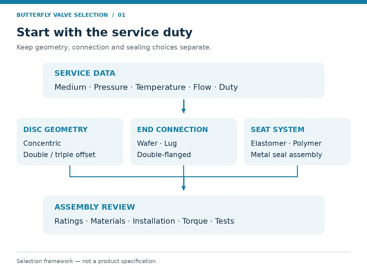
1. How to Select a Butterfly Valve: A Practical Decision Sequence
Treat selection as a sequence of acceptance gates. Resolve the duty before comparing construction, then verify the complete assembly before releasing the purchase order.
On small screens, scroll tables horizontally to view all columns. Keyboard users can focus a table and use the arrow keys.
| Selection gate | Decision to make | Evidence needed before approval |
|---|---|---|
| Service | Isolation, throttling or modulating control? | Operating cases, failure consequence and flow requirements |
| Construction | Which geometry and sealing system can meet the duty? | Section drawing, seat description and operating envelope |
| Materials | Are all exposed components compatible? | Component material list and service compatibility review |
| Installation | Does the valve fit the pipeline and maintenance arrangement? | General arrangement, flange details and disc-clearance drawing |
| Operation | Can the operator move and seat the valve under the specified conditions? | Valve torque basis, actuator output and utility conditions |
| Acceptance | What demonstrates that the supplied valve meets the specification? | Approved deviations, inspection plan and required records |
Keep classification dimensions separate. “Triple-offset” describes sealing geometry; “lug” describes a body connection arrangement; “metal-seated” describes a sealing system. These terms may form part of one specification, but none completes it. Compare the available industrial butterfly valve options after defining these requirements.
2. Define the Service Conditions Before Comparing Valve Types
Start with the actual fluid and the full operating envelope. Include composition, concentration, phase, solids, cleaning chemicals and credible upset conditions. A water designation may conceal seawater, treatment chemicals or abrasive sediment. A chemical name without concentration and temperature is insufficient for material review.
Record normal and design pressure and temperature separately. State upstream and downstream pressure for relevant flow cases, as well as the maximum differential pressure across a closed valve. Consider startup, shutdown, reverse pressure, vacuum and transients where applicable.
Define shut-off acceptance in measurable terms: test standard, leakage criterion, test fluid, pressure, duration and direction. Also state operating frequency, anticipated idle periods and the consequences of failure to open or close. These inputs affect seat selection, shaft design, actuation and inspection scope.
For modulating duty, provide minimum, normal and maximum flow cases. Pipe diameter alone cannot establish the required valve capacity or usable control range.
Illustrative RFQ scenario — design conditions omitted: an enquiry lists normal cooling-water conditions but no design case or minimum temperature. A quote based only on normal operation leaves pressure-boundary and sealing limits unresolved. Confirm the owner’s design envelope, minimum temperature and thermal cycles, then check the proposed body, bolting, seat, stem seals and flange gaskets against those cases before approval.
When the Data Are Incomplete
Mark a missing value as an open item, with a responsible party and a required response. A preliminary quotation may state explicit assumptions; technical approval should wait until the requirements affecting suitability are resolved.
| Open condition | Hold the decision on | Request before technical approval |
|---|---|---|
| Maximum shut-off differential or reverse pressure is unknown | Closure rating and actuator selection | Defined pressure cases and required pressure direction |
| Downstream pipe removal is required | Dead-end use of the proposed valve | Model-specific retained-pressure limits and required hardware |
| Cleaning exposure or vacuum is unspecified | Seat, lining and secondary seals | Cleaning conditions and minimum absolute pressure |
| Modulating duty has no flow cases | Valve size and usable control travel | Minimum, normal and maximum flows with corresponding pressures |
3. Compare Concentric, Double-Offset and Triple-Offset Designs
Concentric Butterfly Valves
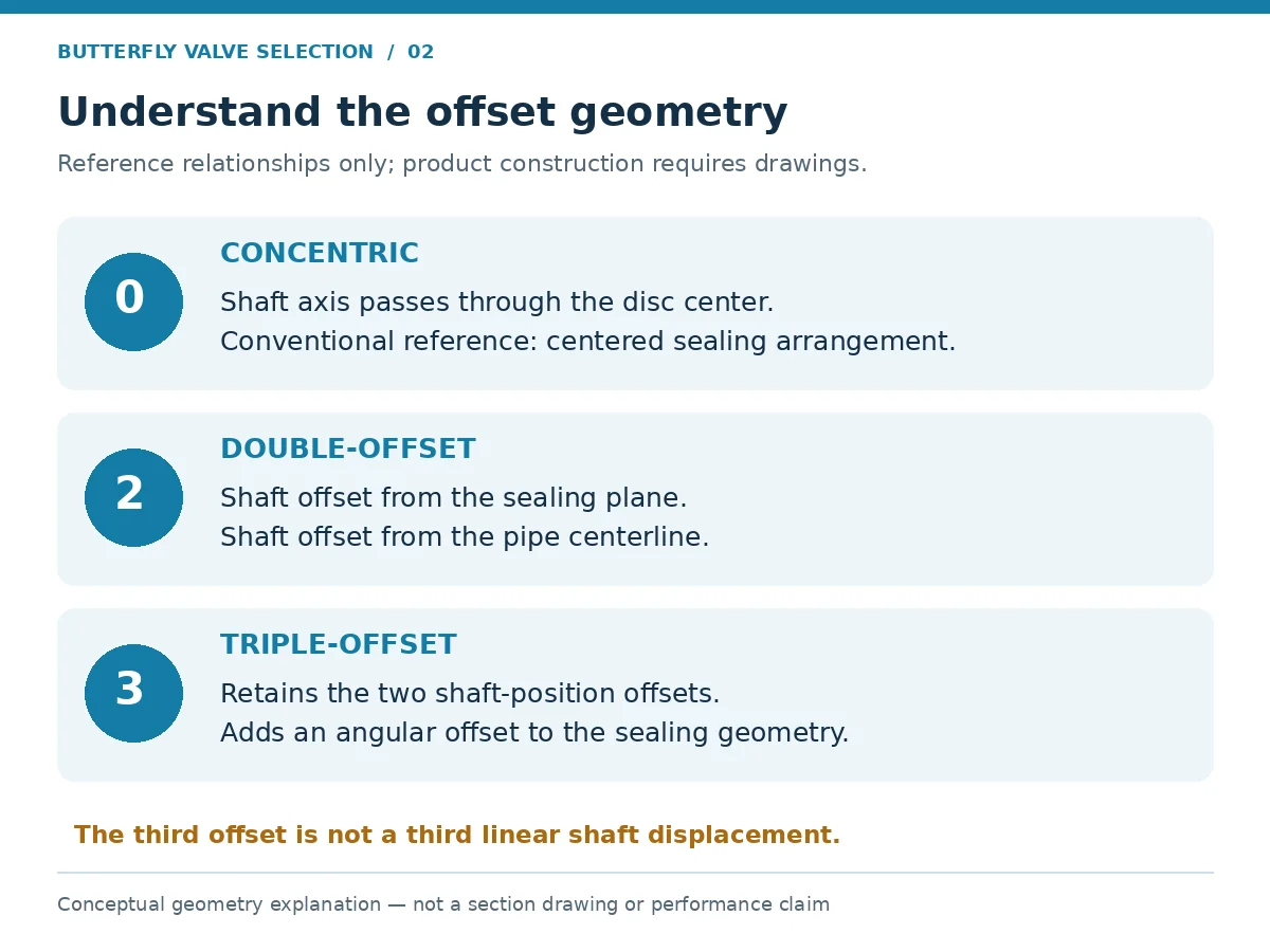
In a conventional concentric design, the shaft axis passes through the disc center and the sealing arrangement commonly uses a resilient seat. This is a starting point for evaluating utility isolation where the proposed seat compound and valve rating match the service.
Check the actual liner construction, retention and replacement method. Confirm whether the liner isolates the body from the fluid and what happens at shaft penetrations and flange interfaces. Do not assume that every concentric valve has the same pressure rating, material exposure or maintenance procedure.
Double-Offset Butterfly Valves
Double-offset geometry displaces the shaft from the sealing plane and the pipe centerline. The opening motion can lift the disc clear of the seat over much of its travel; a manufacturer technical manual illustrates this cam action for a specific design. Seat construction and performance still require separate review. [5]
Evaluate the proposed design for process isolation or control using its pressure-temperature envelope, differential-pressure limits and leakage data. “High performance” is a product description, not a substitute for those records.
Triple-Offset Butterfly Valves
Triple-offset designs add an angular offset to the sealing geometry. Common industrial designs use metal sealing systems and torque seating. They are candidates for duties where temperature or other service requirements exclude the proposed resilient or polymer seat.
Specify the complete seal assembly, including any laminated elements, retainers and secondary seals. Confirm closing torque and sealing direction. Triple-offset construction alone does not prove fire-test qualification, bidirectional shut-off or suitability for abrasive solids.
| Design route | Initial screening question | Required follow-up |
|---|---|---|
| Concentric / resilient-seated | Can the seat and complete valve meet the utility or process duty? | Compound compatibility, pressure-temperature limits and liner details |
| Double-offset | Does this construction improve the fit for the stated isolation or control cases? | Seat system, flow data, differential-pressure limits and torque |
| Triple-offset / metal-seated | Does the duty justify this sealing construction? | Seal assembly, closure acceptance, torque and qualification coverage |
Use these screening directions to build an evidence-backed shortlist.
4. Choose Wafer, Lug or Double-Flanged End Connections
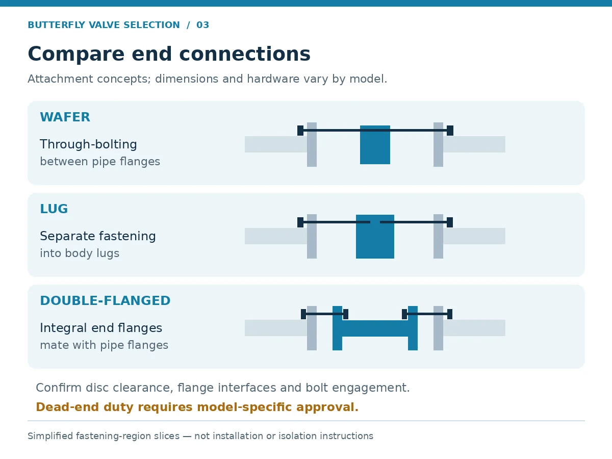
This guide focuses on wafer, lug and double-flanged installations. Other specified interfaces require their own approved connection, dimensional and installation details; the three arrangements below are not an exhaustive list.
Wafer valves fit between mating pipe flanges and commonly use through-bolting. Lug valves use body lugs that allow separate fastening to each adjoining flange in many designs. Double-flanged valves have integral end flanges. Confirm the actual arrangement from the manufacturer’s drawing rather than the product name alone. [1]
Dead-End Service and Downstream Pipe Removal
Dead-end duty means the valve may retain pressure with the downstream pipe or flange removed. Specify this condition explicitly, including pressure, temperature, pressure direction and support arrangement.
Do not authorize dead-end use merely because a valve is lugged. Obtain a model-specific statement of allowable duty and any reduced pressure rating, restrictions or required downstream hardware. Bolting independence and pressure-retaining capability are separate questions. Downstream maintenance must follow the plant’s approved isolation and depressurization procedures.
Illustrative replacement scenario — flanges fit, disc clearance is unknown: a replacement valve matches the flange drilling, but the actual lined-pipe bore or adjacent fitting may intrude into the disc swept envelope. Compare the manufacturer’s clearance drawing with the installed bore and equipment arrangement before acceptance. An apparent nominal-size match does not authorize operation or field modification.
Disc Clearance, Dimensions and Flange Compatibility
Compare the disc swept envelope with the actual pipe bore, lining, adjacent fittings and equipment. The cited manufacturer IOM provides model-specific minimum pipe-bore clearance requirements, illustrating why nominal size alone is insufficient. Obtain the equivalent drawing or clearance requirement for the proposed valve. [6]
Check face-to-face dimensions, flange standard, facing, bore and drilling together. The cited double-offset IOM specifies flange gaskets for that construction. This is a model-specific instruction, not a universal rule for wafer or lug valves. Confirm gasket requirements, bolt engagement, tightening, alignment and external-load limits from the supplied valve’s approved instructions. [6]
| Connection | Useful screening consideration | Approval condition |
|---|---|---|
| Wafer | Compact installation between flanges | Bolting, centering, liner interface and disc clearance are confirmed |
| Lug | Separate flange fastening and maintenance layout | Thread details and any dead-end duty are explicitly approved |
| Double-flanged | Flanged piping interfaces and project layout | Rating, dimensions, loads, support and clearance are verified |
5. Select Body, Disc, Shaft, Seat and Packing Materials Together
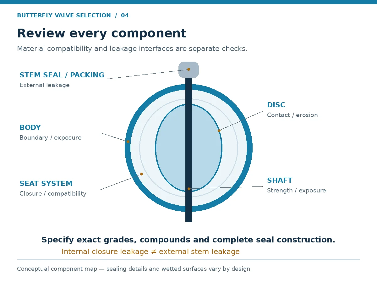
The body material is only one part of the corrosion and sealing review. Identify every wetted component and every barrier relied upon to prevent fluid contact. Include the disc edge, shaft interfaces, fasteners, seal retainers and secondary seals.
Ductile iron, carbon steel, stainless steel, bronze and special alloys may appear in different constructions. Their suitability depends on the precise grade, manufacturing condition, medium and service envelope. A coating or lining adds its own requirements for integrity, adhesion, damage inspection and operating limits.
For chemical or seawater review, record concentration, pH, chloride level and cleaning exposure where relevant, together with temperature, velocity, solids and shutdown conditions. Ask which degradation mechanisms need assessment: pitting or crevice attack, stress-corrosion cracking, erosion-corrosion, elastomer swelling or permeation. If H₂S is present, specify the actual environment and applicable material-qualification requirements; an alloy name alone does not resolve that review.
Elastomer Seats: Compound-Specific Compatibility
EPDM, NBR and FKM are material families. Specify the actual compound and review its process and cleaning exposure at the relevant temperatures. Parker’s O-ring material-selection resource uses temperature, polymer group or hardness, and fluid compatibility as separate selection inputs. This supports the need for detailed seal inputs; an O-ring selection tool does not approve a butterfly-valve seat or its assembled operating envelope. [7]
For a proposed EPDM water-service seat or NBR oil-service seat, document the actual fluid, additives, concentration and cleaning conditions. A material-family label or higher purchase price does not close compatibility review.
PTFE-Based Seats and Linings
Distinguish a PTFE-based seat from a fully lined valve. Identify the grade, fillers, backing components and exposed interfaces. Review deformation, retention, permeation and vacuum capability with the manufacturer where relevant. Chemical resistance of the polymer alone does not establish the pressure-temperature rating of the assembled valve.
Metal Seats and Seal Assemblies
Review the mating materials, surface treatment, seal construction and achievable leakage criterion under specified test conditions. A metal seat may address a temperature requirement while introducing different torque, leakage or particle-damage considerations.
Do not treat metal seating as automatic protection against slurry wear. Solids concentration, particle size, hardness, velocity and cycling determine the severity of abrasion and seat contamination.
Packing also needs a separate review. Internal seat leakage and external stem leakage are different acceptance questions; evidence for one does not resolve the other.
Turn Material Descriptions into Reviewable Requirements
| Offer description | Clarification to request | Acceptance basis |
|---|---|---|
| EPDM, NBR or FKM seat | Exact compound and relevant service restrictions | Compatibility review covering process and cleaning exposure |
| PTFE-based seat or lined valve | Grade, fillers, backing and exposed components | Assembly envelope including any vacuum restrictions |
| Metal-seated construction | Seal materials, secondary seals and mating surfaces | Specified closure criterion and operating torque basis |
| Stainless or coated disc | Exact grade or coating system and coverage | Material schedule, exposure review and agreed inspection |
6. Verify Ratings, Shut-Off Duty and Flow Performance
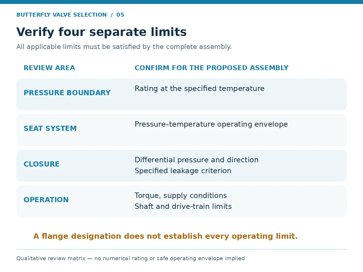
Ask the supplier to distinguish four limits: the pressure boundary rating, the seat pressure-temperature envelope, allowable differential pressure, and operating or actuation limits. Pressure class is a designation, not a fixed allowable pressure: establish the applicable material group, temperature and rating basis. Normal pressure cannot replace design pressure, and seat or secondary-seal limits may control before the pressure boundary does.
A flange drilling designation does not establish seat shut-off capability. Likewise, a closure test performed at one condition does not prove sealing performance throughout the operating envelope. Document the controlling limit and any conditional restrictions in the technical offer.
Isolation Duty Versus Modulating Control
An isolation valve is reviewed primarily for its open-flow and closed-pressure cases, operation and closure acceptance. A modulating valve also requires capacity and stability checks across the expected control range.
Request Cv or Kv data versus opening and identify the conditions and method behind those values. A full-open coefficient is not the capacity at every operating position. Supply fluid properties and corresponding upstream/downstream pressures for each flow case so the reviewer can assess velocity, cavitation, flashing, choking, noise and hydrodynamic torque as applicable. Check minimum-flow control as well as maximum capacity; steady-state sizing does not establish acceptable surge or other transient behavior.
Final Cv, diameter and operating-travel decisions require the actual flow cases and validated data for the proposed design.
7. Match Manual, Pneumatic or Electric Operation to the Duty
Manual operation requires acceptable effort, access and installation space. Pneumatic and electric packages require a defined failure response, duty cycle, operating time and control interface. Include ambient temperature, enclosure or hazardous-area requirements and accessory loads in the package review; an actuator mounting fit does not establish torque or functional suitability.
Obtain the valve torque requirements through the full travel, including unseating, running and seating conditions. Establish their basis: differential pressure, temperature, seat condition, flow direction and service assumptions. Confirm the permitted shaft and drive-train torque as well.
For pneumatic actuators, compare the available output through travel at the specified minimum supply pressure, including spring-stroke capability where applicable. For electric actuators, review output, duty rating, power supply, seating control and torque limits. Loss of power or air does not establish a fail position unless the complete package provides it.
Agree the sizing allowance with the manufacturer and project requirements. Avoid applying an unexplained universal margin. Excessive output can damage the valve, while insufficient output can prevent full travel or seating. Operating time also needs system review where rapid movement can create pressure transients.
Illustrative actuator scenario — catalogue torque looks adequate: the offer compares a catalogue output with a single valve torque value, but omits minimum air supply and the required spring-driven stroke. The comparison is incomplete. Request valve torque and actuator output through travel under the specified conditions, check the failure stroke and permitted drive-train torque, and document the sizing allowance before accepting the package.
8. Screen Butterfly Valve Options by Application
Use application labels to identify questions, then select from the actual service data. The following matrix is a preliminary review tool, not an approved material or construction schedule.
| Application | Candidate direction to evaluate | What can prevent approval? |
|---|---|---|
| Water and HVAC | Compatible resilient-seated construction | Treatment chemicals, surge, temperature, unsuitable flange interface or missing water-contact approvals |
| Chemical processing | Compatible alloy or lined construction | Incomplete composition, exposed incompatible components, permeation or vacuum restrictions |
| Steam and thermal duty | Temperature-qualified seat and sealing assembly | Unsupported seat envelope, thermal cycling, leakage requirement or inadequate operating torque |
| Seawater | Reviewed wetted-material and coating system | Chloride corrosion, galvanic interaction, coating damage or unsuitable shaft/fastener materials |
| Solids-bearing service | Construction supported for the actual solids duty | Particle accumulation, erosion, seat damage or unacceptable operating torque |
| Modulating process duty | Design with usable flow and control data | Inadequate range, cavitation, choking, noise or excessive dynamic torque |
Example Decision Path: Cooling-Water Isolation
Illustrative assumptions: the duty is on/off isolation, with defined water chemistry, no downstream pipe removal, known flange interfaces and operating pressures supplied by the owner. A concentric resilient-seated design can enter the shortlist if its complete rating and materials match those inputs. This is a screening example, not an approved construction.
If the owner instead requires downstream pipe removal, reopen the connection and dead-end review. If the duty changes to continuous modulation, reopen sizing, flow-performance and dynamic-torque review. Changes in function or installation can invalidate a previous shortlist even when nominal size stays the same.
9. Specify Standards, Testing and Required Documents
Build a requirement map rather than a list of standard numbers. The valve standards guide can support the distinction between product, rating, dimensional and test requirements.
| Requirement | Reference and evidence approach | What it does not establish alone |
|---|---|---|
| Butterfly-valve product requirements | Specify the applicable API 609 edition where required; API lists a tenth-edition update dated May 2026 [2] | Compatibility with the actual process or every installation arrangement |
| Ratings and construction | ASME lists B16.34-2025 for valves within its material and construction scope [3] | Universal applicability to every butterfly valve or seat system |
| Pressure and closure testing | ISO 5208:2015 remains current after confirmation in 2025; apply it with the relevant product-standard requirements [4] | Fire performance, emissions qualification or service-life prediction |
| Installation interfaces | Record the applicable flange and face-to-face standards and editions | Disc clearance, support or acceptable piping loads |
| Special qualification | Request applicable fire, emissions, cryogenic or other reports when specified | Qualification of designs outside the documented coverage |
Agree the contract edition and any transition requirements before quotation approval. Publication of a new edition and its application to a particular order are separate matters. General standard references do not prove that a Raymon Valve model is certified or qualified.
Keep shell, closure and functional test records distinct. A pressure test does not prove the absence of all internal material defects or replace specified NDT. PMI checks chemistry within its method and scope; it does not replace mechanical-property or heat-treatment records. Conversely, a material certificate needs identification and traceability to the supplied component. Define any required NDT method, coverage and acceptance separately. Review valve pressure testing when setting the inspection plan.
Required records may include an approved drawing and datasheet, material certificates, traceability records, pressure-test reports, functional results, actuator sizing documentation and the installation and maintenance manual. Define hold, witness and review points before production where the project requires them.
10. Prepare a Butterfly Valve RFQ and Compare Supplier Offers
Make each supplier answer the same requirement. A quotation that lists size, body material and actuator model can still leave the seat compound, maximum shut-off differential pressure and acceptance basis undefined.
| RFQ field | Buyer input | Supplier confirmation / acceptance record |
|---|---|---|
| Function and process | Isolation/control; fluid composition, phase and solids | Suitability statement and open technical questions |
| Operating envelope | Normal/design pressure and temperature; vacuum and transients | Applicable ratings and exclusions |
| Flow and closure cases | Relevant flows and pressures; maximum shut-off differential | Capacity review, closure direction and allowable differential |
| Mechanical interfaces | Size, flange details, face-to-face, pipe bore and lining | Approved drawing and disc-clearance confirmation |
| Maintenance arrangement | Dead-end duty, removable downstream piping and supports | Specific approved duty and restrictions |
| Materials | Body, disc, shaft, seat, packing and coating requirements | Component material schedule and deviations |
| Leakage acceptance | Standard, criterion, fluid, pressure, duration and direction | Test procedure and required report |
| Operation | Frequency, travel time, fail action and available utilities | Torque basis and operator/actuator selection |
| Inspection and documents | Records, witness points and special qualifications | Agreed inspection plan and document list |
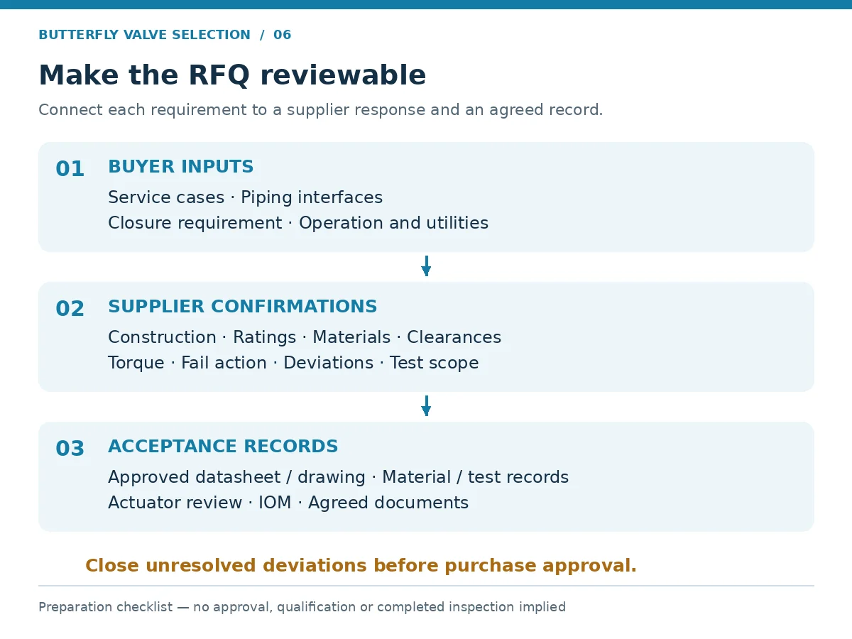
Record deviations explicitly. Mark missing information as unresolved, rather than treating silence as compliance. Close the approved material schedule, operating envelope, installation interfaces and test scope before purchase approval.
When reviewing suppliers, connect capability claims to relevant evidence and the order scope. The Raymon Valve company information provides background; the technical offer and agreed records must establish the supplied assembly’s requirements.
Normalize the Technical Bid Before Comparing Price
| Difference between offers | Make the comparison equivalent | Close with |
|---|---|---|
| Same body class; different shut-off capability | Specified differential pressure, temperature and direction | Supplier-confirmed valve and seat limits |
| Same actuator label; different sizing assumptions | Valve torque basis, minimum utility and fail stroke | Sizing record and drive-train limit review |
| Same leakage claim; different test conditions | Fluid, pressure, duration, direction and acceptance criterion | Agreed procedure and report scope |
| Different inspection or documentation inclusions | Required records, witness points and exclusions | Priced scope and approved deviation schedule |
Classify each requirement as confirmed, deviation requiring approval or open. Assign each open item an owner; record accepted deviations in the datasheet, drawing and order before comparing the final commercial scope.
11. Frequently Asked Questions
How do I choose between concentric, double-offset and triple-offset butterfly valves?
Screen the required temperature, pressure differential, medium, leakage acceptance and operating duty against each proposed design. Compare actual seat systems and manufacturer data. Geometry alone does not determine suitability. What is the difference between wafer, lug and double-flanged connections?
They describe different piping attachment arrangements. Compare them using the project’s flange interfaces, space, support and maintenance requirements, then confirm the proposed assembly drawing. Can a lug butterfly valve be used for dead-end service?
Only when the manufacturer confirms that duty for the exact construction, size, pressure, temperature and pressure direction, including required hardware and restrictions. Lugged construction alone is insufficient approval. How should butterfly valve seat materials be selected?
Review the exact compound or seal assembly against the process fluid, concentration, temperature, differential pressure, cleaning exposure, solids and cycling. Check the assembled valve’s limits as well as material compatibility. Can a butterfly valve be used for throttling?
An appropriate design may be evaluated for throttling, but it needs flow data and review of the intended operating range, pressure drop, noise, cavitation and dynamic torque. An isolation rating does not establish control performance. What information is needed to size the actuator?
Provide the manufacturer’s valve torque data and basis, operating differential pressure, seat system, temperature, movement time, cycle duty, minimum utility conditions and required failure action. Confirm drive-train limits and the agreed sizing allowance. What should a butterfly valve RFQ include?
Include service cases, size and interfaces, construction and materials, shut-off acceptance, actuation, maintenance conditions, applicable standards, inspection scope and documents. Request a clear deviation schedule.
12. Request a Butterfly Valve Selection Review
Submit your existing datasheet or provide the valve function, medium and composition, size and flange standard, normal and design pressure and temperature, maximum shut-off differential pressure, leakage requirement and operation method. For control duty, include the flow cases. Add drawings and flag dead-end duty, vacuum, solids and special qualification requirements.
If information is unavailable, identify it as open and request a review of the missing inputs, proposed construction, technical deviations and required documents. Keep assumptions visible in the enquiry so the offer can address them explicitly.
Request Butterfly Valve Selection Review
Engineering Note
This guide supports preliminary screening and RFQ preparation. Its examples and review tools are illustrative; no model-specific rating, compatibility approval, torque calculation or qualification is established here. Final acceptance requires the project requirements, manufacturer evidence and responsible engineering review.
References
- DeZURIK — Butterfly Valve Selection: Key Styles and Application Factors, August 2025. Primary manufacturer overview; cited for end-connection descriptions only. It does not establish Raymon Valve product performance.
- API — Monogram and APIQR Latest Updates. Official listing includes the API 609 tenth-edition update dated May 2026. Confirm the purchased standard and contract requirements before specifying detailed clauses.
- ASME B16.34 — Valves: Flanged, Threaded, and Welding End. Official page lists the 2025 edition and scope.
- ISO 5208:2015 — Industrial valves: Pressure testing of metallic valves. Official page confirms current status following review in 2025 and describes its relationship to product requirements.
- Bray 4-Cx Double Offset Butterfly Valve Technical Sales Manual, design discussion, printed page 4 (2025). Supports the mechanism example only; its ratings, service-life statements and qualifications are not Raymon Valve claims.
- Bray 4-Cx Installation, Operation and Maintenance Manual, piping compatibility and installation, printed pages 13 and 18 (2024). Supports the model-specific clearance and gasket examples only; use the supplied valve’s approved IOM for installation.
- Parker O-Ring Selector: Material Selection Inputs. Supports temperature, material and fluid-compatibility input review for elastomeric seals. It does not establish butterfly-valve seat compatibility, dimensions or pressure-temperature limits.
 English
 German
 Arabic
 French
 Spanish
 Italian
 Portuguese
 Russian