
Functions of Control Valves in Process Control
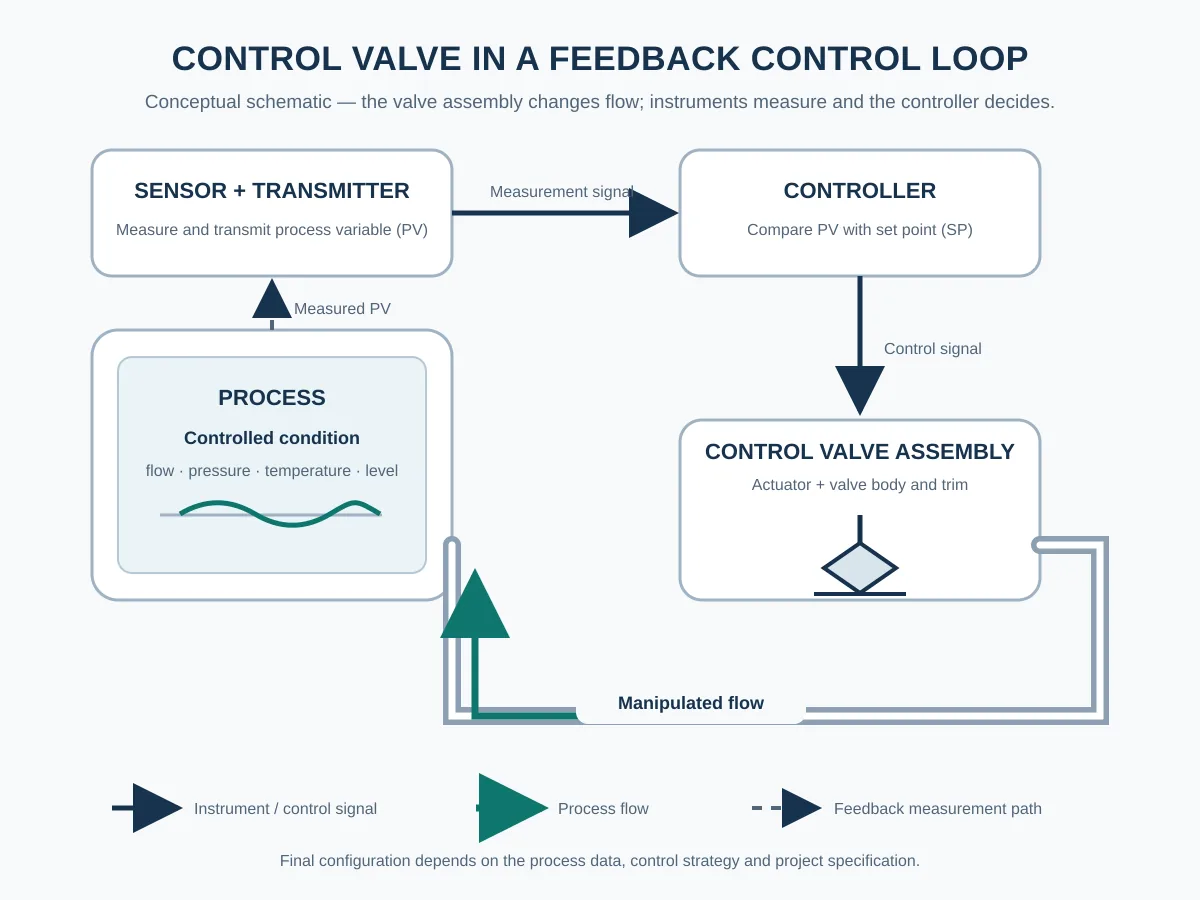
Industrial control valves change fluid flow so a control loop can maintain flow, pressure, temperature or liquid level within its required operating range. In an externally actuated feedback loop, instruments measure the process, a controller compares the measurement with its set point, and the valve assembly responds to the control signal. For engineers and buyers, the practical task is to define the operating cases, shutoff requirements and supplier evidence before selecting a valve package.
How Industrial Control Valves Work in a Control Loop
A typical feedback loop includes a sensor, transmitter, controller and final control element. The controller sends a signal to the valve assembly. The actuator moves the closure member, changing the available flow area. A positioner may help the actuator follow the requested position, depending on the selected package.
Review globe control valve configurations against the confirmed duty, trim requirements and operating cases.
The performance of industrial control valves depends on the whole loop: instrumentation, control strategy, valve capacity, actuator response and process conditions must support the required performance. Valve position alone does not determine actual flow; pressure drop, fluid properties and the installed system also affect the result.
Which Process Variables Can Industrial Control Valves Regulate?
The valve manipulates fluid flow. The measured variable and the process arrangement determine whether the loop controls flow directly or influences pressure, temperature or liquid level.
| Control objective | Valve contribution | Data to define |
|---|---|---|
| Flow | Changes the flow area to adjust process flow. | Minimum, normal and maximum flow, fluid properties and available pressure drop. |
| Pressure | Changes flow to influence pressure at the specified sensing point. | Upstream and downstream pressures, control-point location and supply or demand changes. |
| Temperature | Adjusts heating or cooling medium flow within a temperature-control loop. | Temperature range, heat load, utility conditions and required response. |
| Liquid level | Adjusts inlet or outlet flow in response to level feedback. | Level range, vessel conditions, inflow/outflow cases and required fail action. |
These duties describe what industrial control valves must achieve within the loop. Valve construction, trim, actuator and control strategy must be reviewed against the actual operating cases.
Modulating Control, Shutoff and Diversion Duties
Modulating industrial control valves move through intermediate positions to adjust flow. An on-off valve operates between defined open and closed states. Adding an actuator to a valve does not by itself establish stable throttling performance across the required operating range.
For example, a valve that follows the control signal during normal operation may still lack sufficient closing force at the maximum shutoff differential pressure. Assess that condition with the minimum specified actuator supply and the selected seat design; require the actuator assessment and agreed leakage-test evidence before accepting the combined control and shutoff duty.
For industrial control valves, specify shutoff separately from modulating performance. State the allowable leakage, test basis and maximum shutoff differential pressure, together with the actuator supply conditions. If mixing or diversion is required, define the port arrangement, flow paths and transition sequence for a suitable valve construction.
Turn the Control Function into Measurable Requirements
When specifying industrial control valves, a label such as “temperature control valve” identifies the loop objective but leaves the valve package undefined. Specify the operating cases and the evidence needed to assess each duty. Suppliers of industrial control valves should identify assumptions, exclusions and deviations against the same cases.
| Decision area | Purchaser input | Evidence to request |
|---|---|---|
| Capacity across operating cases | Flow, inlet/outlet pressure, temperature and fluid properties for each relevant case; identify units and pressure reference. | A sizing calculation identifying inputs, method, assumptions, selected capacity and predicted operating positions for the proposed trim. |
| Control response | Required control range, response criteria, signal/interface and available actuator supply. | The proposed inherent valve characteristic, its expected installed behavior, actuator/positioner configuration and performance data with the applicable test conditions. |
| Shutoff duty | Maximum shutoff differential pressure, flow direction, supply conditions and leakage acceptance. | Actuator force/torque assessment and a defined seat-leakage test basis. A capacity calculation alone does not establish shutoff performance. |
| Failure response | Required action for the identified loss of air, power or control signal, as determined by the project’s process review. | Package drawings, accessory logic and a functional test procedure addressing the specified failure scenarios. |
In a low-demand operating case, a package may pass the maximum required flow yet provide poor control near its lower operating limit. Compare the proposed trim capacity and predicted travel at minimum demand with the required controllability and supplier performance data. A full-open published Cv is a rated capacity under stated reference conditions, not the flow available at every operating position.
An inherent flow characteristic describes flow versus travel at constant pressure drop. Installed behavior also reflects pressure-drop changes in the actual system. Evaluate the proposed characteristic against the operating cases rather than selecting it from the controlled-variable name alone.
Assess pressure-drop effects on industrial control valves across the operating envelope. Where relevant, request the supplier’s review of cavitation, flashing, choked flow, noise and outlet velocity using the actual fluid properties and proposed construction. A flow-capacity result alone does not resolve these service risks.
Example: Defining a Heating-Medium Control Duty
For a heat exchanger, the measured variable may be process outlet temperature while the valve adjusts heating-medium flow. Identify the sensing point, temperature range, heat-load cases and heating-medium pressure, temperature and phase. Ask the supplier to show the proposed operating positions across the relevant duties. The project control review must determine controller action and failure response; the temperature-control label alone does not establish valve size or fail position.
Information Needed to Review Industrial Control Valves
- Controlled variable, set-point range and required response.
- Medium, composition, phase and relevant fluid properties, including solids or fouling where relevant; identify material, seat and packing constraints.
- Minimum, normal and maximum flow cases, plus relevant startup or upset cases.
- Upstream and downstream pressure and temperature for each operating case, with units and absolute/gauge pressure identified. Provide design pressure and minimum/maximum design temperature separately for pressure-boundary and material review.
- Available or allowable pressure drop, line size, pressure class and connections.
- Shutoff leakage acceptance and test basis, maximum shutoff differential pressure, operating frequency and required fail action for the identified loss of air, power or signal.
- Actuation method, available power or air supply, signal/interface, installation constraints and project documentation requirements.
Review the pressure-temperature rating of the selected construction and materials against the project design conditions. A pressure class is not a fixed allowable pressure at every temperature, and normal operating pressure does not replace the design basis.
To prepare operating cases for industrial control valves, use the control valve sizing input guide to prepare the operating cases for capacity and configuration review.
Selection boundary: Line size alone does not determine the required size or Cv of industrial control valves. Actuator selection also requires the selected valve’s force or torque requirements, differential pressure, operating time, supply conditions and fail action. Final selection depends on the complete datasheet and project specification.
Self-operated regulating valves use process energy and a mechanical or pilot sensing arrangement. Identify the required control method before comparing them with externally actuated control-valve packages.
Control Valve Function FAQ
What is the main function of a control valve?
It changes process-fluid flow to help a control loop regulate a specified variable, such as flow, pressure, temperature or liquid level. Do industrial control valves measure the process variable?
In an externally actuated feedback loop, sensors and transmitters provide the measurement. The controller evaluates it and sends a command to the valve assembly. Is a control valve the same as an on-off valve?
A modulating valve adjusts through intermediate positions. An on-off valve operates between specified open and closed states. Define the required duty and performance when specifying the package. Can a control valve also provide shutoff?
Suitability depends on the valve assembly and stated shutoff requirement. Specify the leakage acceptance, applicable test basis, differential pressure and actuator supply conditions. What information is needed before selecting a control valve?
Provide the controlled variable, medium, flow range, upstream and downstream pressures, operating and design temperatures, available pressure drop, line details, shutoff acceptance and actuator supply/failure-response requirements. Confirm the proposed valve and trim against the complete datasheet.
Request Sizing Support for Industrial Control Valves
Send the medium, control objective, minimum/normal/maximum flow, upstream and downstream pressure, temperature, line size, shutoff requirement and available actuator supply. Attach the datasheet and project specification, identify missing inputs, and state which sizing calculations, actuator assessments, leakage tests and functional records are required for technical approval.Submit Your Control Valve Data
Engineering note: This module explains control functions and RFQ preparation. The example is illustrative and contains no project-specific sizing recommendation. Product performance, materials, acceptance criteria and failure response require review against the approved project documents.
Technical references: Emerson, Control Valve Handbook, Chapters 1–2; ISA — Process Control Basics, Chapter 5. These general references explain control-loop principles; product suitability requires project-specific review.
 English
 German
 Arabic
 French
 Spanish
 Italian
 Portuguese
 Russian