
Industrial process control · Types and selection
The main types of control valves can be classified by body and trim construction, linear or rotary motion, actuator power source, and special service duty. These labels describe different features of the assembly. A globe valve, for example, describes a body style; pneumatic describes an actuator arrangement. The suitable combination depends on the process cases, control objective, pressure drop, shut-off requirement, fluid, materials, installation and project specification. A type name alone does not determine valve size or service suitability. On this page
- Types of Control Valves: Quick Classification
- Service screening matrix
- What makes a valve a control valve?
- Types of Control Valves by Body and Trim
- Linear and Rotary Types of Control Valves
- Types of Control Valves by Actuation
- Types of Control Valves for Special Service
- How to choose a control valve type
- Control valve RFQ checklist
- Compare supplier proposals
- Request a project-specific control valve review
- Frequently asked questions
Types of Control Valves: Quick Classification
| Classification axis | Common options | What the label describes |
|---|---|---|
| Body and trim | Globe and angle bodies; globe trim may use cage guiding. Rotary options include V-port ball, butterfly and eccentric rotary. | The flow path and throttling construction |
| Motion | Linear or rotary | How the closure element moves through its operating range |
| Actuation | Pneumatic, electric or hydraulic | The power and control arrangement that moves the valve |
| Service trim | Standard, low-noise, anti-cavitation, staged or other engineered trim | A design response to defined process conditions |

These classifications apply together to different types of control valves. A rotary V-port ball control valve can be paired with a pneumatic actuator, for example. A regulator that operates from process pressure is a related pressure-control device, but it should not be confused with an externally actuated modulating control valve. For system-level valve functions such as isolation, modulation, non-return and pressure protection, see the valve function guide.
Which service conditions change the shortlist?
Use the following questions to compare types of control valves before shortlisting a body and trim. A candidate remains provisional until the supplier checks every stated operating case.
| Service concern | What to compare | What must be resolved before selection |
|---|---|---|
| Wide flow range or low-flow control | Available trim capacities, travel/rotation at each case, installed characteristic and package response | Minimum and maximum required flow must fall within the proposed assembly’s demonstrated controllable range; a catalog rangeability ratio alone does not establish this. |
| High liquid pressure drop | Body and trim options, pressure-recovery behavior and pressure-staging approach | Assess cavitation, flashing and velocities using actual pressures, temperature and fluid properties; an anti-cavitation label alone is insufficient. |
| Gas or steam noise | Trim proposal, operating travel, outlet conditions and connected piping | Define noise acceptance and prediction basis. Identify all flow cases, gas properties and piping assumptions. |
| Solids, fouling or abrasive service | Flow passages, guiding, clearances, materials and maintenance access | Describe particle size/concentration and plugging or wear risks. Confirm that the proposed passages and trim are appropriate for the actual medium. |
| Demanding shut-off | Seat design, leakage acceptance, differential pressure and actuator load | Name the test standard/edition, class or acceptance criterion, test conditions and direction. A body type alone does not establish shut-off performance. |
| Utility loss or required fail position | Actuator, accessories, stored energy and control circuit | State which supply or signal is lost and the required valve response. Confirm the full assembly and its test basis, rather than inferring failure action from actuator type. |
What makes a valve a control valve?
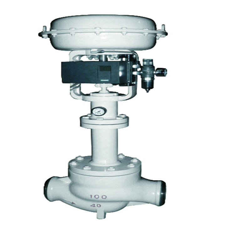
For the externally actuated modulating valves covered here, the control valve assembly changes its flow passage in response to a controller signal. The valve, actuator and required accessories form the final control element. The complete assembly may include the valve body and trim, actuator, positioner, signal converter, solenoid, limit switches and other specified accessories.
The process controller, measurement devices, control logic and valve work together. The valve does not control a process variable simply because it can be partially opened. It must respond over the required operating range, and the installed valve behavior must suit the process. A valve selected only by line size may have poor controllability or may not pass the required flow. A valve selected only by a generic type label may also miss shut-off, material, actuator or documentation requirements.
Control-valve duty is usually modulating, while a simple on/off valve is intended to move between defined open and closed states. Some valve designs may serve more than one duty, but that capability needs to be confirmed for the actual model, service, actuator and acceptance criteria.
Illustrative review scenario: A valve is requested at the same nominal size as the pipe, but the proposed trim passes normal flow near its closed position. The capacity may be excessive for the control duty. Compare required Cv/Kv and predicted travel at minimum, normal and maximum flow, with the actual system pressure drop and model data. Review alternative trim capacities before selecting the body size.
IEC 60534-1:2023 provides industrial-process control-valve terminology and general considerations. Its scope is a terminology/framework reference, not proof of a particular product’s certification or service suitability.
Types of Control Valves by Body and Trim
Compare types of control valves by the required flow path and control task, then check the proposed trim and actuator against every operating case. The comparison below defines screening directions; it does not establish model availability or final suitability.
| Construction | What makes it worth comparing | Selection-changing checks |
|---|---|---|
| Globe body with specified plug, seat and guiding | Compare when the duty calls for a defined throttling characteristic or a choice of replaceable trim arrangements. Cage guiding is one construction feature, not a separate body family. | Required capacity and travel at every case; shut-off; guiding and passage cleanliness; actuator thrust; bonnet and maintenance access. |
| Angle body | Compare when the piping arrangement requires a change in flow direction or the service needs review of an angle flow path. | Exact body/trim geometry, flow direction, outlet conditions, piping loads and access. Flashing or erosion suitability requires application review. |
| Characterized V-port ball | Compare a rotary design when a shaped port is proposed to produce the required throttling response. | Port geometry and capacity curve; installed operating range; pressure recovery; seat/material limits; shut-off and actuator resolution. |
| Butterfly control design | Compare a disc-based rotary construction when package space and flow capacity are key selection considerations. | Disc/seat design, useful controllable travel, differential-pressure limits, recovery/noise behavior and actuator torque across travel. |
| Eccentric rotary design | Compare an offset plug/disc arrangement when its specific seating and throttling geometry is offered for the process. | Manufacturer drawing, flow direction, capacity curve, wear/solids review, required torque and documented shut-off basis. |
| Three-way body | Compare when the process must mix two streams or divert a stream between branches. | Correct mixing/diverting construction and port map, individual branch flows and pressure drops, allowable cross-port leakage and failure response. |
Globe-style control valves
Globe-style control valves use a moving plug or related throttling element and a seat within a globe-pattern body. Seat arrangement and guiding describe different design features. A globe-style valve may use a single-seat or double-seat arrangement; cage guiding is a trim/guiding feature that can occur within a globe-style construction. Identify both the body pattern and the actual trim arrangement in the datasheet. For general construction and port-arrangement context, see Spirax Sarco’s control-valve tutorial. Its steam/water examples do not establish the internal construction or performance of a Raymon product. The guiding and trim arrangement, pressure drop, required capacity, shut-off, maintenance access and fluid cleanliness all affect the selection.
A globe-style label does not state the valve’s capacity, leakage acceptance, control range or suitability for a specific pressure drop. Those details must be specified and checked for the service. Where a particular product is being considered, review its approved datasheet and drawings. Raymon’s globe control valve and cage-guided control valve pages provide product-specific review routes; they do not replace tag-level sizing or approval.
Angle control valves
An angle control valve changes the direction of flow through the body. Its layout may help address a piping arrangement or particular flow-path requirement, but the body form alone does not prove that it will reduce erosion, flashing, noise or pressure loss. Review inlet and outlet conditions, piping loads, flow direction, available space, maintenance access and the actual trim design.
See the angle control valve page for the product-specific configuration questions.
Rotary control valves
Rotary control valves regulate flow through angular movement. Examples include characterized V-port ball, butterfly and eccentric rotary designs. They may be considered where quarter-turn movement or the intended body arrangement fits the installation, but performance depends on the selected construction and the complete operating range.
Compare required flow capacity, installed flow characteristic, shut-off, pressure recovery, actuator output, control resolution, materials and maintenance needs. The V-port ball control valve is one product-specific route for reviewing a characterized rotary design. Do not assume that a general-purpose isolation ball or butterfly valve is suitable for continuous throttling without the manufacturer’s application confirmation.
Three-way, diaphragm and pinch arrangements
Three-way designs may be considered for mixing or diverting duties when the required flow paths, operating cases and leakage criteria are defined. Diaphragm and pinch-style arrangements may be relevant in particular process services, but the media, solids, temperature, pressure, cleaning method, materials and maintenance requirements must be checked against the exact product construction.
Specify these types only after confirming the offered model and its service envelope. For abrasive, corrosive, slurry, hygienic or high-purity duty, document the particular material, construction, cleaning and acceptance requirements.
Two-way throttling or three-way mixing and diverting?
A two-way control valve varies the restriction in one flow path. A three-way arrangement connects three ports for a specified mixing or diverting task. For mixing, define the two inlet streams and combined outlet; for diverting, identify the common inlet and the two outlet branches. Use the supplier’s port diagram rather than assuming port letters or flow arrows are universal.
Supply each branch flow and its corresponding inlet/outlet pressure for the operating cases. Confirm the body/plug arrangement is intended for the specified mixing or diverting direction, plus the allowed cross-port leakage and required response on utility loss. A three-way valve is not automatically interchangeable between these duties. The linked Spirax Sarco tutorial illustrates two-port and three-port arrangements in its steam/water context; apply the exact product and process limits to an industrial project.Illustrative assembly description
“Two-way globe body, single-seat cage-guided trim, pneumatic linear actuator, positioner and specified accessories” combines the body/port arrangement, seat/guiding design, motion and actuator in one description. Capacity, characteristic, materials, shut-off, failure action and test requirements remain separate datasheet decisions. This example is not a product offer or a sizing result.
Linear and Rotary Types of Control Valves

Linear-motion valves move the closure element along a straight path; rotary valves turn it through an angular range. This describes movement, not the power source or the controlled process variable.
| Review point | Linear-motion design | Rotary design |
|---|---|---|
| Movement | Stem travel | Angular rotation |
| Examples | Globe and angle bodies, including applicable cage-guided trim arrangements | V-port ball, butterfly, eccentric rotary |
| Installation questions | Stem clearance, actuator envelope, access and support | Rotation clearance, mounting orientation, actuator interface and access |
| Engineering checks | Required travel, guiding, trim, pressure drop and shut-off | Characteristic, pressure recovery, range, shut-off and actuator output |
The table screens types of control valves by motion. Neither motion type is inherently best for every application. Compare the actual design, process conditions and control-loop requirements.
Types of Control Valves by Actuation

Pneumatic actuation
A pneumatic actuator uses compressed air to move the valve. The specification should define available supply pressure, signal and control interface, required travel or rotation time, operating frequency, accessories and the required response to loss of air or power. Define the required safe state from the process safety and control philosophy; do not infer it from the word “pneumatic.”
Illustrative review scenario: An actuator is selected using normal air supply and normal differential pressure, yet the required failure stroke must occur at a different load. That leaves the worst-case thrust or torque unconfirmed. Check the load throughout travel, maximum applicable differential pressure, minimum utility, packing/seat friction, accessory demand and agreed margin; then verify the specified failure response of the complete package.
Electric actuation
An electric actuator uses electrical power and may include a control unit, position feedback and other package accessories. Confirm supply voltage and frequency, duty, modulation requirements, environmental classification, controls, response time, interface and failure strategy. The exact actuator and valve combination must be checked against the process load throughout travel.
Hydraulic actuation
Hydraulic actuation may be considered where the project provides and accepts a suitable hydraulic power and control arrangement. Confirm the required supply, control interface, response, package scope, failure response and maintenance provisions. Selection depends on the complete installation and service requirements.
Actuator type is a separate choice from body construction. A globe body can be configured with an appropriate actuator, just as selected rotary bodies can be automated, subject to model-specific interfaces and engineering confirmation.
Self-operated pressure regulators
A self-operated regulator uses energy from the process medium or another directly sensed process condition to regulate pressure or another defined variable without the same external controller-actuator arrangement used by a typical modulating control valve. The exact device and sensing arrangement matter. See the regulating valve selection guide when the requirement is pressure regulation by a self-operated device.
Types of Control Valves for Special Service
Some designs use specialized trim or flow paths to address a defined noise, cavitation, flashing, pressure-staging or erosion concern. An “anti-cavitation” or “low-noise” name indicates a design objective; it does not guarantee elimination of the phenomenon or establish a performance limit.
For liquid service, cavitation and flashing review requires relevant pressure and temperature cases, fluid properties and the valve’s recovery behavior. For gas or steam service, noise and velocity concerns require the applicable process data and sizing method. The manufacturer should identify the assumptions, selected construction and evidence supporting the proposal. Review the anti-cavitation control valve or low-noise control valve pages only as product-specific starting points.
How to choose a control valve type
- Define the control objective. Identify the controlled variable, required operating modes and consequence of losing control.
- Provide the operating cases. Include minimum, normal and maximum flow, plus startup, shutdown or upset cases that affect selection. Provide fluid composition and properties, upstream and downstream pressure, differential pressure and temperature.
- Screen body and trim options. Consider required capacity and control range, shut-off criterion, fluid phase, solids, pressure recovery, cavitation/flashing/noise concerns and maintenance access.
- Review materials and interfaces. Specify body, trim, seat, packing and gasket requirements, end connection, pressure-temperature rating, flow direction and installation constraints.
- Coordinate the actuator and controls. Define power or utility, control signal, feedback, accessories, required response time and failure action. Confirm the valve-actuator package against the maximum load cases.
- Complete project sizing and documentation review. Use a recognized sizing method with verified process data and model-specific coefficients. Record assumptions, deviations, acceptance criteria, required tests and turnover documents in the project specification.
IEC 60534-2-1 addresses flow-capacity sizing equations under installed conditions. The published scope limits its incompressible-flow equations to the relevant Newtonian-fluid conditions; it excludes several complex fluid systems and calls for caution with non-vaporizing multicomponent liquid mixtures. Identify the fluid regime and confirm that the selected method applies. Confirm the governing project edition and method before relying on a calculation.
Check rating, materials and seals as one assembly
Pressure class is a rating designation, not a fixed operating pressure. Check the applicable material group and temperature against the governing pressure-temperature basis, then confirm any more restrictive body, bonnet, bolting, trim, seat, packing or gasket limits. Operating conditions do not replace design pressure and temperature. Include minimum temperature, maximum temperature and thermal cycling where relevant.
Review wetted and sealing parts individually against the medium, concentration, temperature, velocity, solids, cleaning fluids and shutdown conditions. A suitable body alloy does not establish compatibility of the stem, trim, seat, packing or gasket. Seat and trim choices affect shut-off and wear; packing affects external leakage, friction and actuator load; gasket selection affects pressure-boundary joints. Sour, cryogenic, emissions or fire requirements need their own applicable scope and evidence when specified.
Illustrative review scenario: A body has an acceptable pressure-temperature rating, but the proposed seat or packing has not been checked against the hottest operating or cleaning case. The assembly limit may therefore be lower than the body rating. Obtain component material limits and confirm the complete proposed construction against all temperature cases before approval.
Specify the data basis, not just the numbers
Identify whether each pressure is absolute or gauge, state flow units, and give the reference conditions for gas volume where relevant. Keep design limits separate from operating cases. Supply inlet and outlet pressures for each corresponding flow case; unrelated maximum values do not define a valid sizing case. Mark missing values as open points for review.
Cv and Kv express flow capacity on different defined reference bases; record which coefficient and units the proposal uses. Rated full-open capacity is different from capacity at the predicted operating position. Use the selected trim’s coefficient-versus-travel data and applicable sizing factors; a published maximum Cv/Kv or line size does not demonstrate low-flow control, acceptable velocity or transient behavior.
Separate inherent and installed flow behavior
Linear and equal-percentage labels describe inherent flow characteristics under specified conditions. The connected system changes the pressure drop available to the valve as flow changes. Ask for the proposed trim characteristic and expected operating travel across the actual system cases; a characteristic label alone cannot establish installed control quality.
Control valve RFQ checklist
To compare types of control valves, provide the following information on the same technical basis:
- Valve tag, quantity, controlled variable and required function.
- Fluid composition, phase, properties and any solids or contamination.
- Minimum, normal, maximum and relevant transient flow cases.
- Inlet/outlet pressure, differential pressure, design and operating temperature.
- Line size, pressure class/rating, end connections, flow direction and installation constraints.
- Required shut-off or leakage criterion, operating frequency and control range.
- Body, trim, seat, packing, gasket and bolting material requirements.
- Noise, cavitation, flashing, erosion or other service limits, when applicable.
- Actuator power or utility, control signal, accessories, feedback, response time and failure action.
- Applicable standards and editions, inspection and test plan, witness points, documents, deviations and acceptance criteria.
Ask the supplier to identify the sizing basis, model and trim, actuator load basis, assumptions and unresolved inputs. Do not use pipe diameter or pressure class alone to determine the control valve size.
What evidence should accompany the proposal?
Compare quotations for different types of control valves against the same process cases and acceptance criteria. Record each assumption and deviation so a lower price cannot hide a different trim, actuator or inspection scope.
| Review item | Required supplier submittal | Purchaser comparison point |
|---|---|---|
| Sizing and trim selection | Sizing sheet identifying tag, process cases, fluid properties, units, method, proposed trim and relevant valve coefficients | Same cases and units; required capacity and proposed travel/rotation; disclosed assumptions and method limits. |
| Installed control behavior | Selected inherent characteristic and case-specific operating range; response information where specified | Confirm the basis for low-flow control and stable modulation; do not treat catalog rangeability as installed turndown. |
| Actuator and controls | Valve torque/thrust load basis, minimum available utility, actuator selection, fail response, signal and accessory schedule | Check the stated load cases, utilities, required stroke time and complete package inclusions. |
| Materials and construction | Tag datasheet, materials list and drawing showing body, trim, seat, packing and piping interfaces | Identify material and construction deviations. Confirm compatibility review against the actual medium and temperature. |
| Inspection and acceptance | Agreed ITP and test schedule, standards/editions, acceptance criteria, witness points and report requirements | Separate shell pressure tests, closure leakage and functional/package tests. Add emissions, fire or other qualification only when required and supported. |
| Final approval | Closed clarification/deviation list and approved datasheet/drawing | Resolve selection-changing open points before manufacturing release; retain the documents that govern supplied scope. |
For pressure-boundary and closure acceptance planning, review the valve pressure-test scope and acceptance records. Specify control-valve leakage and package functional acceptance separately against the applicable project requirements.
Review a product configuration
Use these product pages to review types of control valves and prepare configuration questions before submitting the datasheet. Final availability, construction and documentation depend on the approved scope.
- Globe control valves — body, trim and service-case review.
- Cage-guided control valves — guiding, passage and trim review.
- Angle control valves — flow path and piping-interface review.
- V-port ball control valves — characterized rotary construction review.
- Anti-cavitation configurations — liquid pressure-drop and trim review.
- Low-noise configurations — acoustic target and process-case review.
Request a project-specific control valve review
Send your valve tag or datasheet with the medium, minimum/normal/maximum flow cases, corresponding inlet and outlet pressures, temperatures, line size and control objective. Add the required shut-off criterion, materials, actuator utility and signal, failure response and inspection/document scope. Attach the line class or P&ID if available. Identify missing inputs so the review can first close the data gaps, then establish a project-specific configuration and quotation basis.
Send Control Valve Data for Review
Frequently asked questions
What are the main types of control valves?
Common classifications include body and trim construction (such as globe or angle bodies with the specified trim, V-port ball, butterfly and eccentric rotary), motion (linear or rotary), actuation (pneumatic, electric or hydraulic) and special-duty trim. These are separate classification axes, so a valve can fit one option in more than one category. What is the difference between globe and rotary control valves?
A globe-style valve uses a linear throttling movement in a globe-pattern body, while rotary designs regulate through angular movement. Compare the actual model’s capacity, control range, shut-off, pressure recovery, materials, actuator interface and process duty rather than choosing by type name alone. Are pneumatic and electric control valves different body types?
No. Pneumatic and electric describe actuator power arrangements. The body and trim construction is a separate selection decision, and the complete valve-actuator assembly must be confirmed for the process cases. When should a self-operated pressure regulator be considered?
Consider one when the required pressure-control function and application are suited to a self-operated device. Confirm the sensing arrangement, setpoint and flow range, inlet conditions, outlet or upstream control requirement, shut-off behavior and protection philosophy. The term “regulator” covers different devices, so review the exact configuration. What information is needed to select or size a control valve?
Provide fluid properties, minimum/normal/maximum flow, pressure and temperature cases, required control objective, allowable pressure drop, line and end-connection data, shut-off criterion, materials, actuator requirements and applicable project documents. The manufacturer needs the complete cases and valve-specific coefficients to perform a project sizing review. Does a control valve type determine its Cv or suitability?
No. A construction name does not supply the flow data, operating conditions or model coefficients needed to determine capacity or suitability. Complete sizing and application checks for the actual service are required.Engineering scope
This page supports screening types of control valves and preparing an RFQ. Final size, trim, actuator, materials and acceptance depend on the complete service data and approved project documents. Confirm suitability and supplied scope through the accepted quotation, datasheet, drawings, specifications and required records.








 English
 German
 Arabic
 French
 Spanish
 Italian
 Portuguese
 Russian