
An angle globe valve is a globe-pattern valve with inlet and outlet connections arranged at approximately 90 degrees. It can provide specified shut-off or throttling duty while changing the piping direction inside the valve body, which may simplify a suitable right-angle layout. It is not automatically a low-pressure-drop valve or a substitute for a properly sized control valve. Before selection, confirm the service duty, flow direction, pressure-temperature conditions, trim, materials, piping loads, installation envelope and required inspection evidence.
Engineering boundary: A 90-degree body pattern does not, by itself, prove lower pressure loss, improved control performance or suitability for a particular service. Confirm the selected construction against the approved datasheet, drawings and project specification.
What Is an Angle Globe Valve?
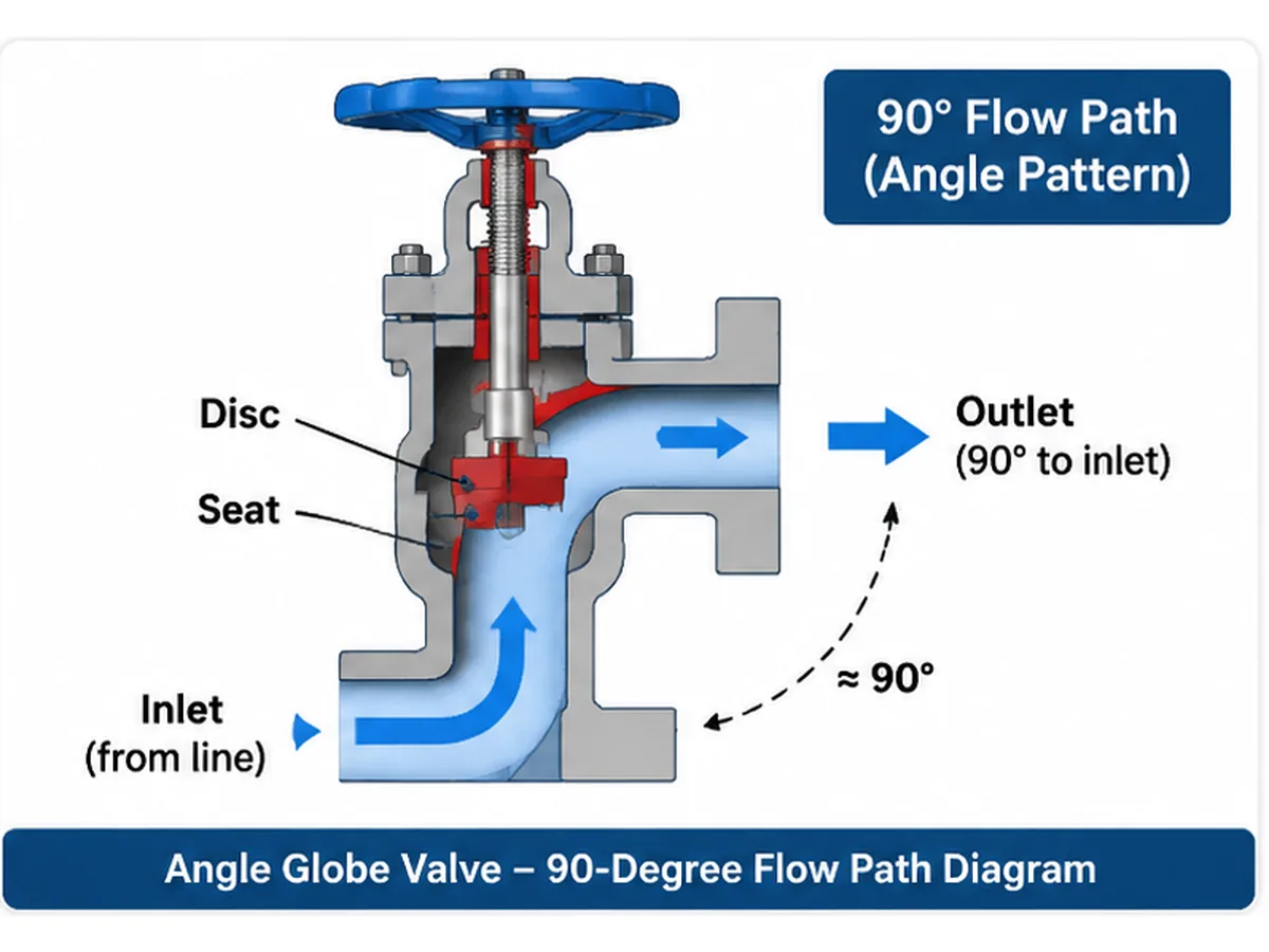
An angle globe valve is a globe-pattern valve whose inlet and outlet are positioned approximately 90 degrees apart. A movable disc or plug approaches or moves away from a stationary seat to change the available flow area. Depending on its design and specified duty, the valve may be used for shut-off, throttling or a defined combination of these functions.
Unlike a conventional straight-pattern globe valve, an angle body changes the flow direction within the valve. In a suitable piping arrangement, this may avoid a separate elbow at the valve location. Whether that arrangement is advantageous depends on the valve dimensions, internal geometry, pressure loss, piping loads, drainage, maintenance access and the total installed piping arrangement. The valve body pattern alone does not establish a lower system pressure drop.
How Does an Angle Globe Valve Work?
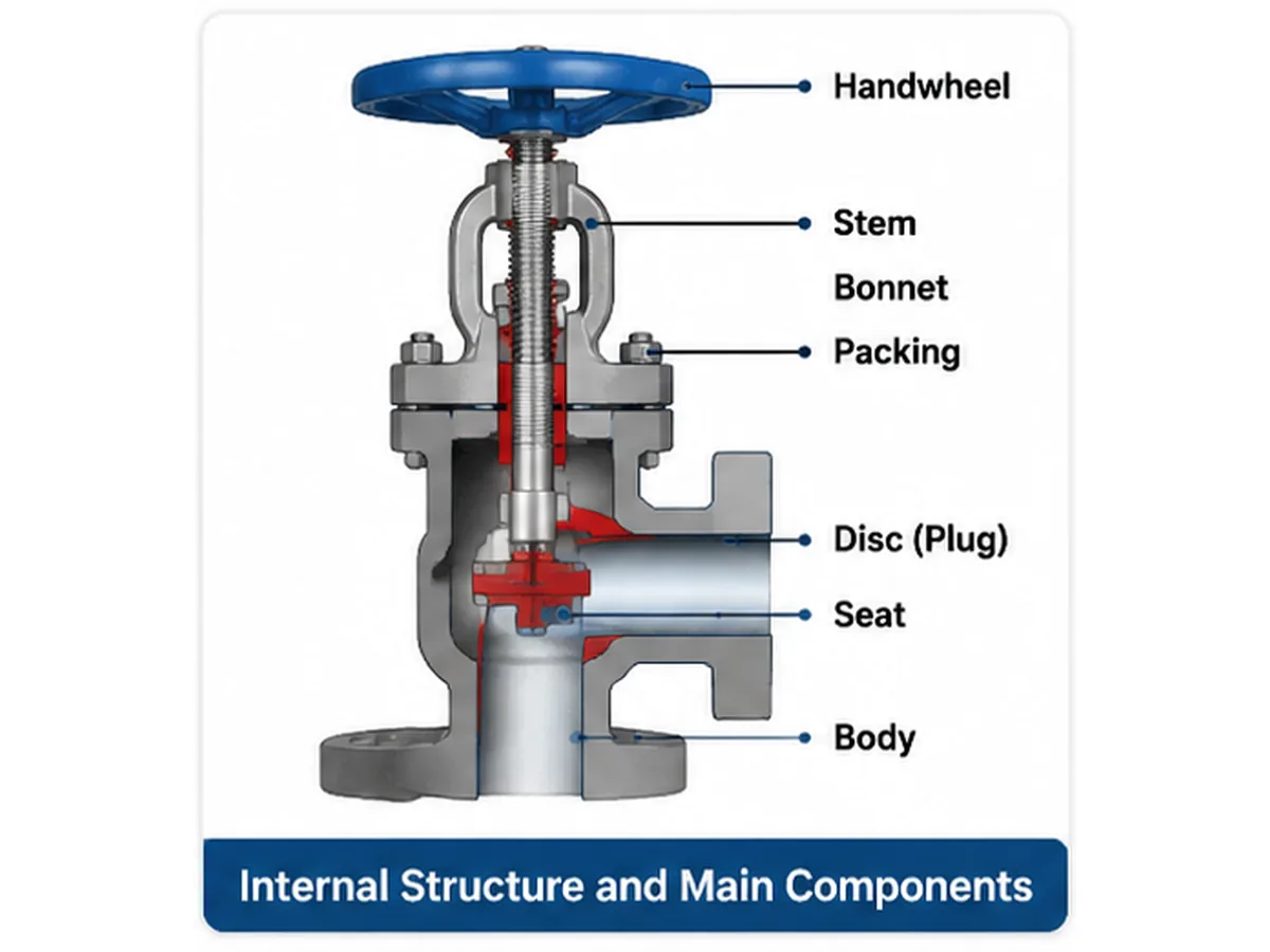
Angled flow passage
Fluid enters through one end connection, passes through the disc-and-seat region and exits through the outlet at approximately 90 degrees to the inlet. The exact passage geometry varies by design. Confirm the specified inlet, outlet and installation orientation from the manufacturer’s approved drawing rather than relying on a generic illustration.
Disc and seat movement
The stem transfers operating movement to the disc or plug. Moving the closure element toward the seat reduces the available flow area; moving it away increases the opening. Seat geometry, trim contour, guiding arrangement, differential pressure and operating direction influence the valve’s behavior and shut-off performance.
Flow direction and pressure drop
Flow direction should be stated in the datasheet and confirmed against the manufacturer’s design. It can affect disc stability, seat loading, stem thrust and operating force. Globe valves introduce flow resistance, and the pressure drop of an angle globe valve depends on the specific body passage, trim, opening position, flow rate and fluid properties. Do not infer a pressure-drop advantage from the 90-degree body pattern alone.
For a manually operated angle globe valve, do not assume that the valve has the characterized flow curve, rangeability or control accuracy of a purpose-designed control valve. If the duty requires continuous modulation, tight process control, anti-cavitation trim or a defined noise limit, specify those requirements and evaluate whether a dedicated angle control valve is required. Obtain model-specific capacity and sizing data before confirming the valve size.
Main Design Features
Body, bonnet and end connections
The angle body combines the valve function and a change in piping direction. Review the body pattern, pressure boundary, bonnet arrangement, end connection dimensions, flow direction, drainage, piping loads and access required for inspection or maintenance.
Disc, plug and seat assembly
The closure element and seat form the principal flow-control and shut-off interface. Their configuration should match the required function, differential pressure, fluid composition, temperature, operating frequency, wear exposure and allowable leakage. The actual trim design must be confirmed from the product drawing and datasheet.
Stem, packing and optional bellows sealing
The stem transmits movement from the handwheel or actuator to the closure element. Packing selection should account for temperature, medium compatibility, operating cycles and external leakage requirements. A bellows-sealed arrangement may be considered where specified, provided the configuration is available and qualified for the service. Confirm any secondary sealing provision and inspection requirements in the RFQ.
Angle Globe Valve vs. Standard Globe Valve
| Comparison | Angle Globe Valve | Standard Globe Valve |
|---|---|---|
| Body configuration | Inlet and outlet are arranged at approximately 90 degrees. | Generally uses a straight-pattern body arrangement. |
| Flow path | Changes direction within the valve body. | Flow path depends on the selected body and port design. |
| Piping layout | May simplify a right-angle connection in a suitable layout. | May require a separate piping elbow depending on the line arrangement. |
| Pressure drop | Must be established from actual body and trim geometry and service data. | Must be established from actual body and trim geometry and service data. |
| Selection priority | Piping configuration, flow direction, pressure loss and service duty. | General globe-valve duty and the existing piping arrangement. |
An angle globe valve may be preferred when the piping layout benefits from an integrated direction change. A standard globe valve may be more appropriate when the existing line arrangement favors a conventional body. Neither configuration should be selected on the assumption that it always produces lower pressure loss or better throttling performance.
Applications and Service Conditions
Steam and thermal systems
For steam or thermal service, review operating and design temperatures, pressure differential, condensate management, thermal expansion, packing suitability, flow direction and the specified shut-off duty.
Power generation
Power applications may involve elevated temperatures, changing operating cases and demanding inspection requirements. Confirm body and trim materials, pressure-temperature limits, end connections, maintenance access and the applicable project specification.
Chemical and petrochemical processing
Review fluid composition, concentration, temperature, corrosion mechanisms, deposits and potential erosion. Body, disc, seat, stem and sealing materials must be evaluated as a compatible combination.
Oil and gas facilities
For process and utility systems, define the required valve function, design conditions, shut-off criterion and documentation scope. Sour-service or other critical applications require a project-specific review of material, hardness, manufacturing and qualification requirements.
Materials and Sealing Selection
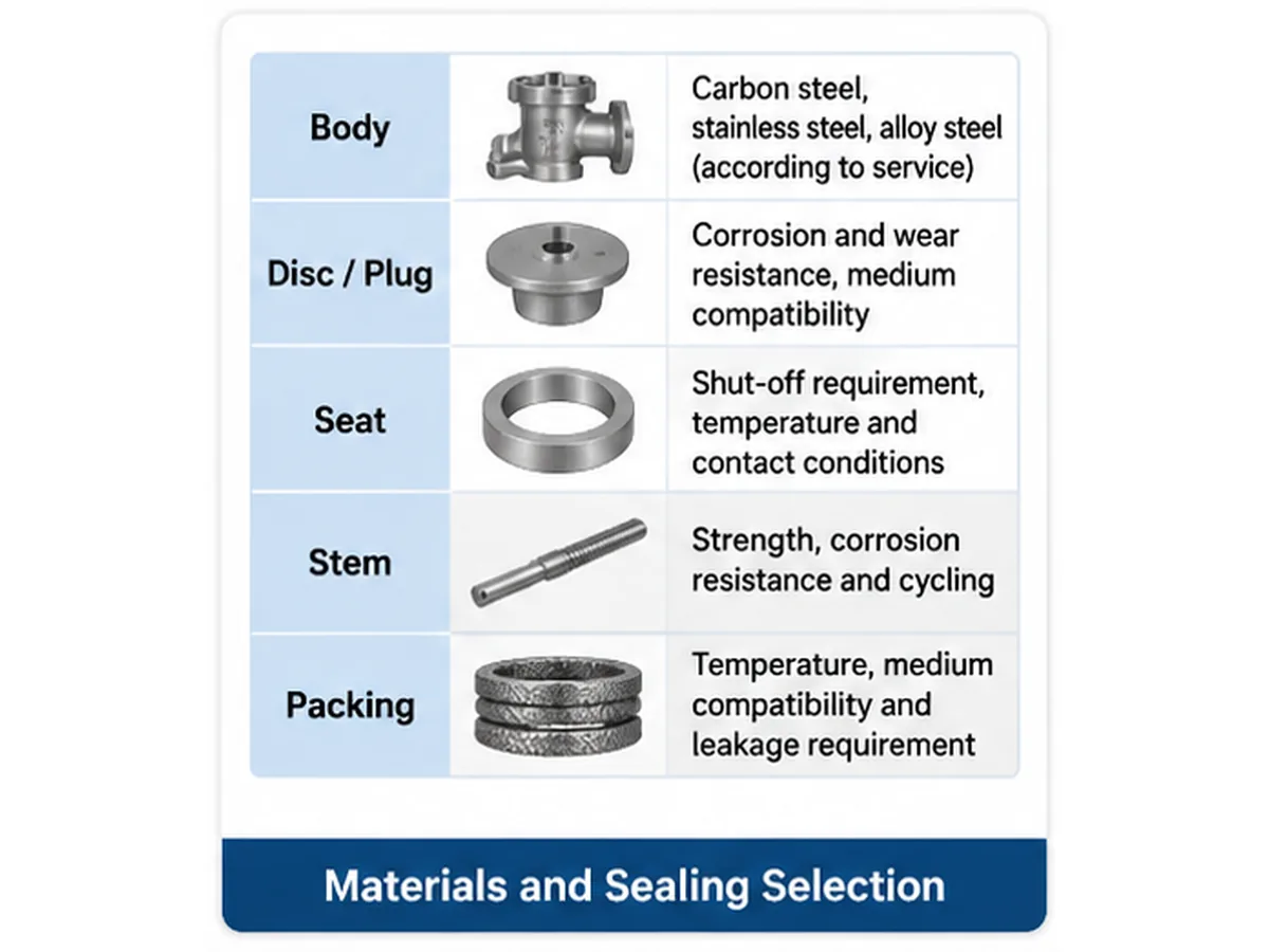
Typical RFQ review issue: A quotation may identify a stainless-steel body but leave the disc, stem, seat and packing grades undefined. The body designation alone cannot establish complete wetted-part compatibility. Ask for the component bill of materials and traceability scope, then compare each wetted material with the actual fluid composition, concentration, temperature and contaminants.
Material selection must reflect the complete operating environment. A body material designation alone does not establish compatibility of the wetted trim, stem, seat, packing or gasket.
| Component | Selection considerations |
|---|---|
| Body and bonnet | Pressure-temperature conditions, corrosion and mechanical requirements. |
| Disc or plug | Medium compatibility, erosion, wear and differential pressure. |
| Seat | Shut-off requirement, temperature and contact conditions. |
| Stem | Strength, corrosion resistance and operating cycles. |
| Packing or bellows | Temperature, medium compatibility, cycling and leakage requirements. |
| Gasket | Pressure, temperature and fluid compatibility. |
Carbon steel, stainless steel and alloy steel are material families, not universal service recommendations. Evaluate the body, bonnet, disc or plug, seat, stem, packing, gasket and bolting as applicable against fluid composition, concentration, phase, temperature, pressure, chlorides or other contaminants, solids, start-up and shutdown conditions, and the expected corrosion or wear mechanism. For corrosive, abrasive or elevated-temperature service, provide the full operating envelope and request confirmation of the offered component materials and qualification basis.
Pressure Rating, Size and End Connections
Specify nominal size, pressure class, design pressure, design temperature, end type and connection standard together. A Class designation is not a single fixed allowable pressure across all materials and temperatures. Verify the applicable pressure-temperature table for the exact material group and construction, and separately confirm the trim, sealing arrangement, bolting, end connection and project requirements. Face-to-face or center-to-face dimensions must match the specified valve type and end configuration.
- Nominal valve size and line size.
- Normal and design pressure and temperature.
- Minimum, normal and maximum flow rates, plus upstream and downstream pressure for each operating case.
- Flanged or welded end connections and applicable dimensions.
- Face-to-face dimensions and approved installation orientation.
- Flow direction, center-to-face dimensions, operator clearance, drainage and maintenance access.
How to Select an Angle Globe Valve
| Selection step | Information to confirm | Engineering purpose |
|---|---|---|
| Medium | Composition, phase, solids and contaminants. | Establish compatibility and flow risks. |
| Pressure | Normal, maximum and design pressure. | Confirm pressure-boundary requirements. |
| Temperature | Normal, startup, shutdown and design cases. | Check materials and sealing. |
| Flow | Flow rate and differential pressure. | Evaluate capacity and pressure loss. |
| Function | Isolation, throttling or combined duty. | Define the required construction. |
| Body configuration | Angle pattern, connection orientation and flow direction. | Confirm piping compatibility. |
| Operation | Handwheel, gear or actuator requirements. | Establish operating and interface needs. |
| Inspection | Test scope, acceptance and documentation. | Define procurement and quality requirements. |
Reconsider the configuration if the available differential pressure cannot support the required flow, the service creates unacceptable erosion or flashing exposure, materials are incompatible, maintenance access is inadequate, or the specified shut-off/control performance cannot be demonstrated.
Pressure-loss, cavitation and flashing review
For liquid service, compare the expected pressure profile through the valve with the liquid vapor pressure at the operating temperature. Cavitation can occur when local pressure falls below vapor pressure and subsequently recovers; flashing is a different condition in which the downstream pressure remains below vapor pressure. These conditions require service-specific evaluation because they can affect noise, vibration, trim damage and downstream piping. Do not infer cavitation or flashing limits from the valve pattern alone.
For gas or steam service, review the pressure ratio, temperature, flow rate, acoustic/noise requirements and any applicable velocity limits. Where the valve is intended for throttling, obtain the manufacturer’s sizing basis and confirm that the selected trim and operating range match the process cases. A generic angle globe valve description is not a substitute for a sizing calculation.
Failure mode, possible cause and verification
| Potential issue | Possible contributing causes | Verification or review |
|---|---|---|
| Seat leakage | Seat damage, contamination, wear or unsuitable shut-off conditions. | Confirm leakage acceptance, inspect seating surfaces and specify the seat test. |
| Stem leakage | Packing degradation, installation issues, stem damage or unsuitable service conditions. | Review packing material, stem finish, assembly requirements and external leakage criteria. |
| Excessive pressure loss | Flow passage restriction, operating position or unsuitable sizing. | Review actual flow cases, differential pressure and documented sizing data. |
| Trim erosion or damage | High local velocity, entrained solids, flashing or cavitation exposure. | Review fluid phase, solids, pressure profile, trim geometry and inspection findings. |
| Difficult operation | High differential pressure, mechanical friction, deposits or actuator mismatch. | Confirm operating conditions, stem/trim condition and manufacturer operating-load data. |
| Corrosion | Incompatible wetted materials or unreviewed process contaminants. | Verify fluid composition and material compatibility for all wetted components. |
Testing, Inspection and Documentation
Typical receiving-inspection issue: A material certificate may match the purchase order while the physical component identity remains unverified. Where the project requires it, define PMI coverage, component identification and traceability links in the ITP. PMI is a supplementary verification method; it does not replace the applicable material certificate, heat-treatment records or full manufacturing traceability.
| Inspection item | What the buyer should specify |
|---|---|
| Material verification | Material grades, certificates and traceability scope. |
| Dimensional inspection | Approved drawings and dimensional tolerances. |
| Shell pressure test | Applicable procedure and acceptance criteria. |
| Seat leakage test | Test medium, direction and allowable leakage. |
| Functional test | Operating movement and functional acceptance. |
| PMI / NDT | Specify components, examination method, coverage, timing, acceptance criteria and records. PMI does not replace MTC; NDT methods are not interchangeable. |
| Final documentation | Approved inspection and turnover document list. |
Identify the applicable test standard and edition, test pressure, test configuration and acceptance criteria in the purchase specification. A shell test primarily evaluates the pressure-retaining boundary under its specified test conditions; it does not replace a closure/seat leakage test. Functional testing, fire-safe type testing, fugitive-emission qualification, cryogenic testing, PMI and NDT address different requirements and must not be treated as interchangeable. State the applicable standard and edition, test medium, pressure, duration, direction, acceptance criteria, witness/hold points and required records in the purchase specification. A standard production test does not automatically establish suitability for every special service.
Supplier technical evaluation: evidence to request
| Evaluation area | Evidence to request | What the buyer should verify |
|---|---|---|
| Product configuration | General arrangement drawing, sectional drawing and datasheet. | Angle orientation, flow direction, dimensions, pressure class and component arrangement. |
| Materials | Bill of materials and applicable material certificates. | Grades and traceability for pressure-retaining and wetted components. |
| Pressure-temperature suitability | Applicable rating basis and product design documentation. | Ratings match body material, design temperature and governing specification. |
| Testing | Approved test procedure, inspection plan and test records as required. | Test scope, acceptance criteria, witness/hold points and traceability. |
| Special service | Service-specific qualification or supporting technical documentation, where required. | Evidence applies to the offered model, materials and stated operating envelope. |
| Deviations | Completed technical deviation list. | Exceptions are visible, reviewed and accepted before order placement. |
Certificates, test reports and qualification records should be tied to the offered valve model, order scope or applicable manufacturing batch. A general company certificate does not prove that every valve configuration meets a project requirement.
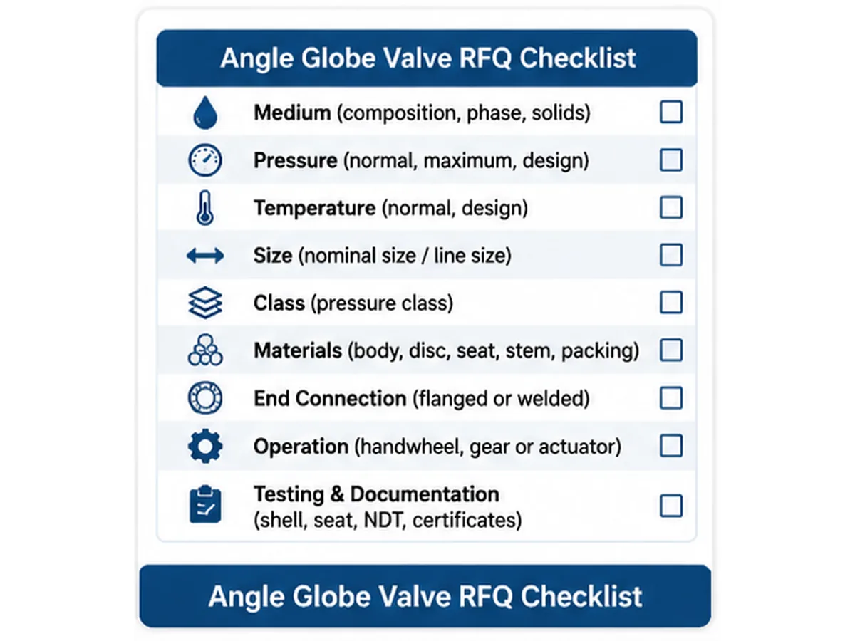
Angle Globe Valve RFQ Checklist
Typical piping-interface issue: A valve may match the nominal line size but still conflict with the required center-to-face dimensions, flow orientation, actuator clearance or maintenance envelope. Attach the piping arrangement or approved GA drawing and identify the controlling dimensional standard before purchase-order release.
- Project name, valve tag number, quantity and line number.
- Fluid name, composition, phase and solids content.
- Normal and design pressure and temperature.
- Minimum, normal and maximum flow rates, plus upstream and downstream pressure for each operating case.
- Nominal size, pressure class and end connection.
- Body, trim, seat, stem, packing and gasket requirements.
- Angle-body orientation and specified flow direction.
- Manual or actuated operation, operating frequency and fail position where applicable.
- Shut-off or throttling requirement and allowable leakage.
- Applicable standards, inspection, testing and documentation requirements.
Providing these details helps the manufacturer identify missing information, clarify technical deviations and prepare a quotation against a defined valve configuration.
Standards and Specification References
Choose standards from the project specification and the exact valve construction. A standard may cover design, pressure-temperature ratings, dimensions or production testing; these scopes are different and should not be substituted for one another.
- API 623: Steel globe valves with flanged and butt-welding ends and bolted bonnets. Its scope includes straight-pattern, Y-pattern and right-angle configurations, subject to the standard’s construction, size, class and other stated limits. The second edition was published in January 2021, with Errata 1 issued in April 2024. Confirm the contractually specified edition and whether the offered valve falls within its scope.
- API 598: Valve inspection and testing. The eleventh edition was published in February 2023. Confirm whether it is invoked by the governing product standard or purchase specification, and define the required examination and pressure-test options and acceptance criteria.
- ASME B16.34: Covers pressure-temperature ratings, dimensions, tolerances, materials, NDE requirements, testing and marking for the valve constructions within its scope. The 2025 edition is listed as current in the available publication catalogue; confirm the project edition and material-specific rating basis.
- ASME B16.10: Covers face-to-face and end-to-end dimensions for straightway valves and center-to-face / center-to-end dimensions for angle valves. The 2022 edition covers center-to-face and center-to-end dimensions for angle valves; confirm the applicable table for the valve type, material, size, rating and end connection.
These are potential specification references, not a declaration that every angle globe valve must comply with all four documents or that Raymon Valve products hold a particular certification. The purchaser and manufacturer should agree the applicable edition, scope, supplementary requirements and acceptance criteria before order placement.
Frequently Asked Questions
What is an angle globe valve used for?
It is used for specified isolation or throttling duties where the piping arrangement requires an approximately 90-degree change in flow direction. It may simplify a suitable layout, but the selected valve must still meet the required capacity, pressure loss, shut-off, materials and installation conditions.
How does an angle globe valve differ from a standard globe valve?
The main difference is the body flow path. An angle globe valve has an approximately 90-degree inlet-to-outlet arrangement, while a conventional globe valve generally uses a straight-pattern body configuration.
Does an angle globe valve reduce pressure drop?
No. The angle body may change the piping arrangement, but pressure drop depends on the actual body passage, trim, opening, flow rate and fluid properties. Compare the selected valve’s documented pressure-loss or sizing data with the complete piping arrangement.
Can an angle globe valve replace a 90-degree pipe elbow?
It may do so in a suitable piping arrangement. Check valve dimensions, end connections, flow direction, maintenance access, piping loads and installation requirements first.
Can a manual angle globe valve be used for modulating control?
It may be used for throttling only where the valve design and operating duty support it. If the process requires a defined control characteristic, rangeability, noise limit or anti-cavitation performance, evaluate a purpose-designed control valve and obtain model-specific sizing data.
Which standards cover angle globe valve dimensions and testing?
The applicable documents depend on construction and project requirements. API 623 includes right-angle steel globe valve configurations within its stated scope; API 598 addresses inspection and testing when invoked; ASME B16.10 addresses relevant angle-valve dimensional conventions; and ASME B16.34 addresses pressure-temperature ratings and other requirements for covered constructions.
What should be checked before replacing a globe valve with an angle pattern?
Confirm end connections, center-to-face dimensions, flow direction, pressure loss, piping loads, drainage, support, operator clearance, maintenance access and the applicable pressure-temperature rating. Do not treat nominal size alone as proof of interchangeability.
Which materials are suitable for angle globe valves?
Carbon steel, stainless steel and alloy steel may be considered depending on the application. Final selection requires review of fluid composition, pressure, temperature, corrosion, erosion and wetted-component compatibility.
What information is required when ordering an angle globe valve?
Provide the medium, pressure, temperature, nominal size, pressure class, flow data, body and trim materials, end connections, operation, leakage requirements, testing and documentation requirements.
Request an Angle Globe Valve Technical Review
Submit the valve tag and line data, fluid composition and phase, minimum/normal/maximum flow, upstream and downstream pressure, design pressure and temperature, nominal size, pressure class, end connections, body and trim materials, required shut-off or throttling duty, flow direction, operation, testing and documentation scope. Attach the piping arrangement or dimensional reference where available. The manufacturer can then identify missing inputs, confirm the proposed configuration and list technical deviations for review.Submit Your Valve Datasheet
Final selection and supplied performance remain subject to the approved project datasheet, technical specification, drawings and order documentation.
Engineering Note
This page provides general product-selection guidance for preliminary technical screening and RFQ preparation. It does not replace project-specific valve sizing, pressure-temperature verification, materials engineering, piping stress review, actuator sizing or approval of the manufacturer’s drawings. Final suitability depends on the complete process datasheet, applicable codes and standards, verified product documentation and purchaser approval.
Author: Raymon Valve Technical Content Team. Technical reviewer: Not specified. Product-specific performance and certification evidence: to be confirmed against the offered model and project documentation.
Related Valve Resources
- Industrial Globe Valve Range — browse globe valve body patterns and related product configurations.
- Industrial Valve Standards Guide — review standards scope and specification boundaries.
- About Raymon Valve — review company information without treating it as product-specific qualification evidence.
 English
 German
 Arabic
 French
 Spanish
 Italian
 Portuguese
 Russian