
Piping compatibility · Replacement review
To match gate valve pipe connections, confirm the service conditions, pipe dimensions, end designation, installed length and operating space together. The same nominal size or pressure class does not complete the check. For industrial metal-pipe replacements, compare the existing valve and field measurements with the proposed supplier drawing before ordering. This guide provides the connection checks, replacement record and RFQ fields needed to identify incompatible offers, resolve missing information and prepare an installation review. Other pipe materials and end types require their own product-specific assessment.
In this guide
- Gate Valve Pipe Compatibility: What Must Match?
- How to Check Gate Valve Size Against the Pipe
- Connection Details to Confirm for Each Gate Valve End Type
- Replacing a Gate Valve: Dimensions to Verify Before Ordering
- Installation Checks Before Connecting the Valve to the Pipe
- Common Gate Valve Pipe Matching Errors
- What Evidence Should Close the Supplier Review?
- Gate Valve Piping RFQ Checklist
- Frequently Asked Questions
- Request a Gate Valve Piping Compatibility Review
Gate Valve Pipe Compatibility: What Must Match?
Start with the line class, process datasheet and piping arrangement. These establish the requirements against which a supplier should propose a valve. Use the following checklist before comparing prices.
On narrow screens, scroll the table horizontally to see all columns.
| Review area | Buyer input | Supplier confirmation |
|---|---|---|
| Service suitability | Medium, composition, normal/design pressure and temperature, operating cases | Proposed construction, materials and applicable pressure-temperature rating |
| Size and bore | Nominal size, pipe outside diameter, wall thickness and bore requirement | Valve bore and mating-end dimensions |
| End connection | Complete flange, weld-end or thread designation | Connection drawing and deviations |
| Installed dimensions | Existing valve dimensions and available installation length | Face-to-face or end-to-end dimension and tolerances |
| Operation and access | Orientation, operating differential pressure, nearby obstructions | Permitted orientation, operator arrangement and clearance envelope |
| Acceptance | Inspection, testing and documentation requirements | Applicable procedures, acceptance basis and records |
Use three approval questions before comparing offers
- Is the valve suitable for the service? Confirm the medium, normal/design conditions, relevant abnormal cases, materials and shut-off requirement against the proposed configuration.
- Does the documented interface match? Compare the connection designation, end dimensions, bore and installed length with the piping specification and existing arrangement.
- Can it be operated, maintained and installed as proposed? Check the full operating envelope, removal access, support arrangement and model-specific instructions.
Keep each question open until its supporting documents are available. A quotation may be ready for commercial comparison while dimensional or service approval remains unresolved. Record who owns each outstanding item and which drawing revision closes it.
Open diagram at full size (new tab)
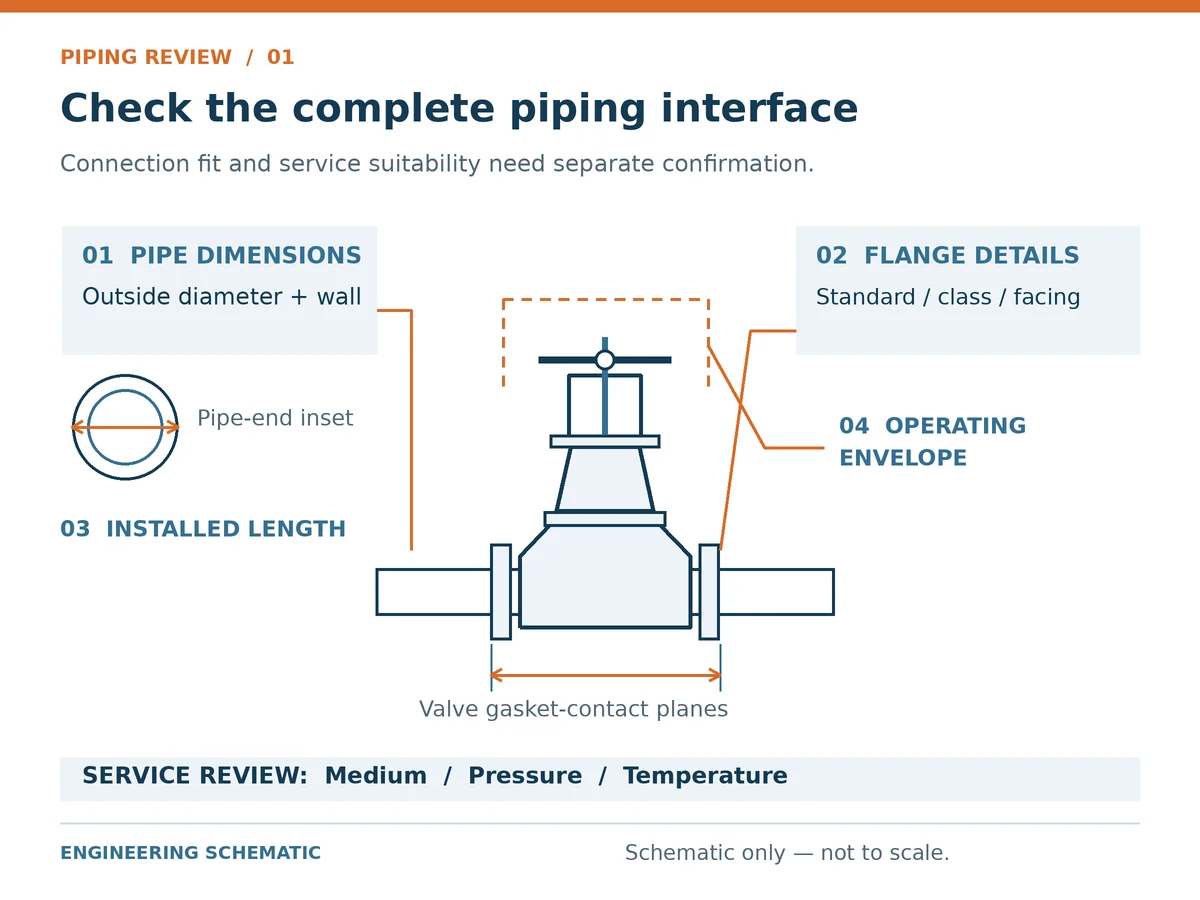
Coordinate service suitability and interface compatibility. Pressure class is a designation, not a fixed allowable pressure: check the relevant material group, temperature and selected product design. Normal operating pressure cannot replace the design requirement. Review minimum and maximum temperature, start-up and shutdown cases, and thermal cycling where relevant. Confirm the applicable limits for the body/bonnet, bolting, seat/trim, packing and gasket; the body material alone does not approve the complete valve. Review operating differential pressure and the required shut-off acceptance basis separately.
How to Check Gate Valve Size Against the Pipe
Use the Gate Valve Guide for broader construction and service selection. The checks here focus on the proposed valve’s piping interface and replacement dimensions.
Nominal size, pipe outside diameter and actual bore
Record the nominal size using the project designation, together with the pipe dimensional standard, outside diameter and wall thickness. Request the proposed valve bore and end dimensions on the supplier drawing.
Do not substitute a measurement of the accessible opening for a complete connection designation. For existing installations, combine drawings, material records, markings and appropriately obtained field measurements. Record discrepancies for engineering review.
Pipe schedule and weld-end bore matching
For welded connections, identify the adjoining pipe material and thickness. Compare the valve end with the pipe end, including internal diameter, preparation and any required transition. A catalog description such as “butt weld” leaves these details unresolved.
The approved drawing should define the interface that the welding procedure and inspection plan will use. Any proposed mismatch or transition needs assessment under the applicable piping and project requirements.
Illustrative fabrication check: a proposed weld-end valve has the correct nominal size, but the adjoining pipe wall differs from the end detail used for the quotation. The missing thickness input leaves bore transition and preparation unresolved. Compare the pipe record with the valve end drawing, record any transition requirement, and obtain the approved detail before fabrication; do not correct the mismatch by unapproved field machining.
Full bore and pigging requirements
If the line must pass a cleaning or inspection tool, state that requirement explicitly. Request confirmation against the tool envelope, minimum clear bore, internal geometry and adjoining components. A “full bore” description alone should not close the pigging review.
Connection Details to Confirm for Each Gate Valve End Type
The four connection groups below are common industrial review routes, not an exhaustive list. PE pipe ends, grooved ends, coupling ends and other constructions need their own product-specific interface review; do not apply the metal-pipe details below to them without confirmation.

Open diagram at full size (new tab)
Flanged ends
For a flanged configuration, review the flanged gate valve product page alongside the complete piping interface and service requirements.
Specify the flange standard, nominal size, pressure class or PN designation, facing, and relevant dimensional series. Coordinate the gasket, bolting, facing finish and mating flange requirements. Record any dissimilar mating materials or proposed facing combination for joint-design review.
ASME B16.5 addresses flange and flanged-fitting dimensions, ratings and related requirements within its stated scope. Its size and class coverage must be checked; it is not a universal specification for every flange.
Ask the supplier to identify the flange details on the drawing. Installation bolt loads and tightening procedures must come from the approved joint assembly basis. A pressure class designation alone does not provide a tightening torque.
Illustrative receiving check: the bolt pattern matches, but the received sealing face appears damaged or does not match the specified facing/finish. Matching holes do not establish joint suitability. Compare the received part with the order, drawing and approved joint specification, record the discrepancy, and obtain disposition before assembly rather than compensating with extra bolt load.
Butt-weld ends
Provide the pipe dimensional standard, material, outside diameter and thickness. Request the proposed bevel, end bore and transition details where relevant.
ASME B16.25 covers preparation of buttwelding ends, including bevel and internal/external shaping requirements. It does not by itself qualify the welding procedure or approve the complete installed joint.
Before fabrication, agree on the welding procedure, heat-treatment and examination requirements where applicable. Confirm any restrictions needed to protect seats, packing or other components from fabrication heat using the valve manufacturer’s instructions.
Socket-weld ends
Confirm the socket details, adjoining pipe dimensions, material pairing and project permission to use this connection. Installation fit-up and welding requirements should be defined by the applicable approved documents.
Do not copy a generic socket gap or welding sequence into the purchase specification without checking its applicability. Obtain the connection drawing and resolve access for welding and examination before installation.
Threaded ends
Specify the exact thread standard and designation, size, internal/external arrangement and sealing method. “Threaded” or “BSP” alone may leave important details open.
Identify the exact standard and mating-thread designation before selecting the sealing arrangement:
- NPT: use the specified NPT designation under ASME B1.20.1; confirm both mating ends and the approved sealing method.
- ISO 7-1: this standard addresses pipe threads where the pressure-tight joint is made on the threads. Confirm the intended internal/external mating designation under ISO 7-1; the label “BSP” alone does not complete the specification.
- ISO 228-1: the parallel fastening threads described by ISO 228-1 use a pressure-sealing arrangement outside the threads. Identify the applicable seal and its mating surfaces.
Do not decide the sealing route from a “parallel” or “tapered” description alone. Verify the complete thread pair, sealing detail and manufacturer’s installation requirements.
Do not approve an uncertain thread combination because the components initially screw together. Confirm identification and use an approved compatible connection or engineered adapter where required.
For broader interface comparisons, see valve end connection types.
Replacing a Gate Valve: Dimensions to Verify Before Ordering

Open diagram at full size (new tab)
Installed length
Record the existing valve’s face-to-face or end-to-end dimension and the available field installation space as separate items. State the measurement reference planes, applicable facing or end configuration, drawing source and required tolerances. Compare the proposed valve drawing with both records; account separately for gaskets, mating joints and any approved piping changes.
Use the dimensional reference planes defined for the applicable standard, flange facing or end configuration and approved drawing. A schematic span between gasket-contact planes is only an illustrative flanged example; it is not a universal reference for every facing. Resolve uncertain reference planes before treating two length measurements as comparable.
ASME B16.10 provides valve installation dimensions for the configurations within its scope. Its interchangeability purpose depends on the specified material, valve type, size, rating class and end connection. Verify the applicable entry and the actual supplied drawing.
Replacement field record to attach to the inquiry
- Identification: valve tag/location, existing model and the confirmed service requirement.
- Interface: end designation, pipe dimensional data, facing or weld/thread details, and their source records.
- Length record: existing valve dimension, measurement reference planes, units, date/source and drawing reference.
- Field space: available installation span, joint/gasket arrangement and any proposed piping work, recorded separately from valve length.
- Access: operating stroke/envelope, maintenance space, removal route and nearby obstructions.
- Closeout: supplier drawing revision, deviations, unknown fields, assigned reviewer and disposition.
Mark each value as a document value, a safely obtained field measurement or an unconfirmed item. Attach a marked-up sketch that identifies the reference planes. Do not estimate inaccessible dimensions and present them as verified measurements.
Operating and maintenance envelope
Check clearance through the complete operating stroke. Include the stem, handwheel, gearbox or actuator, local controls and nearby structures. Separately check the space required for maintenance and valve removal.
A valve may fit into the line while its stem cannot reach the fully open position. A replacement actuator can also change the access requirements even when the valve body length remains compatible.
Illustrative access check: a replacement matches the valve length, but a nearby tray conflicts with the rising-stem envelope or actuator access. Body fit alone has missed the operating space. Overlay the full-stroke and maintenance envelopes on the site layout and agree an approved arrangement before purchase release. These examples illustrate review logic, not reported Raymon Valve projects.
Replacement review sequence
- Identify the existing valve tag and approved service requirements.
- Gather existing drawings, connection information and reliable field dimensions.
- Mark uncertain or conflicting information rather than treating it as confirmed.
- Compare the proposed supplier drawing against each interface and clearance requirement.
- Resolve deviations and any piping changes before purchase release.
Illustrative replacement review: Offer A matches nominal size and class but lacks an installed-length drawing. Offer B includes a dimensioned drawing but proposes a different end connection. Keep Offer A open pending dimensional confirmation; record Offer B as a technical deviation requiring purchaser engineering review. Neither offer is approved from its price or nominal designation alone. This is a hypothetical document-review example, not an installed project result.
Installation Checks Before Connecting the Valve to the Pipe
Identity, condition and cleanliness
Verify the tag, model, materials identification and supplied documents against the approved order. Inspect for transport damage and contamination according to the receiving procedure. Protect sealing surfaces and keep foreign material out of the valve and pipework.
Alignment, support and loads
Review the pipe alignment and support arrangement before joint assembly. Do not use the valve or flange bolting to force misaligned piping into place. Refer unresolved fit-up, weight or external-load issues to the responsible engineer.
Orientation and assembly instructions
Confirm the permitted installation orientation, any directional marking and the operator arrangement against the model-specific installation manual. Use approved lifting points and handling instructions. Stem and handwheel components should not be assumed to be lifting points.
The required valve position during welding, flushing or pressure testing must be established from the approved procedure and manufacturer’s instructions. Avoid applying one rule to all gate valve constructions.
Testing and handover
Distinguish factory valve tests from installed-system inspection and testing. A shell test addresses the pressure boundary under its specified conditions; a closure/seat test addresses shut-off acceptance, while functional checks address operation. Do not substitute one record for another or treat a pressure-test pass as proof of every material or internal condition. Define the test boundary, valve position, allowable differential pressure, acceptance criteria and required records under the applicable project and model instructions before testing.
Replacement and intrusive inspection require the site’s authorized work permit, isolation/LOTO, depressurization and draining arrangements, with gas testing or other controls where applicable. These checks do not authorize work on pressurized equipment. Stop the installation review and involve the responsible engineer or manufacturer when identification, joint condition, dimensional references or approved installation instructions remain unresolved.
Common Gate Valve Pipe Matching Errors
On narrow screens, scroll the table horizontally to see all columns.
| Issue found during review | Evidence to check | Resolution direction |
|---|---|---|
| Same nominal size, unspecified flange interface | Standards, facing, drilling and supplier drawing | Resolve the complete mating designation |
| Replacement body does not match available length | Existing measurements and proposed installed-length drawing | Review another configuration or approved piping modification |
| Insufficient opening or maintenance space | Full-stroke and removal envelopes against the piping layout | Coordinate the construction or installation arrangement |
| Weld-end details are incomplete | Pipe thickness, valve end drawing and welding requirements | Approve the interface before fabrication |
| Thread designation is uncertain | Markings, records and appropriate thread verification | Confirm the thread pair and sealing method |
| Piping must be forced into position | Alignment, support and stress-review records | Resolve the piping condition before assembly |
What Evidence Should Close the Supplier Review?
Ask for documents that identify the offered valve tag, model and configuration. Agree whether each item is required with the quotation, before purchase release, before manufacture or at final handover. The matrix below is a suggested review framework; the contract defines the actual intervention points.
On narrow screens, scroll the table horizontally to see all columns.
| Decision | Evidence to request | How to close the item |
|---|---|---|
| Service and rating suitability | Completed datasheet, proposed materials and rating basis | Review each controlling service case; resolve assumptions and exclusions. |
| Pipe and connection fit | Dimensioned GA and end-detail drawing | Compare with the line class, mating dimensions and field information. |
| Operation and access | Full-stroke envelope, orientation instructions and operator data | Check the site layout; agree the differential-pressure basis for operation. |
| Installation work | Model-specific IOM and applicable joint-assembly or welding documents | Coordinate the valve instructions with approved site procedures before work. |
| Shut-off and inspection acceptance | Agreed test scope, criteria and required inspection/test records | Identify the tested configuration and distinguish factory testing from site testing. |
| Material identity and handover | Specified material records, marking/traceability details and final document index | Check the required records against the supplied tag and order scope. |
Make technical deviations explicit
For each difference, record the specified requirement, offered alternative, drawing reference, effect on piping or installation, responsible reviewer and disposition. Use clear states such as confirmed, open and deviation awaiting approval. Silence in a quotation should not be treated as evidence that a critical interface has been checked.
Close dimensional and service decisions before the relevant purchase or fabrication release. Keep manufacturing records scheduled for later delivery visible in the document register; they cannot be treated as completed evidence at the quotation stage.
Gate Valve Piping RFQ Checklist
Open diagram at full size (new tab)
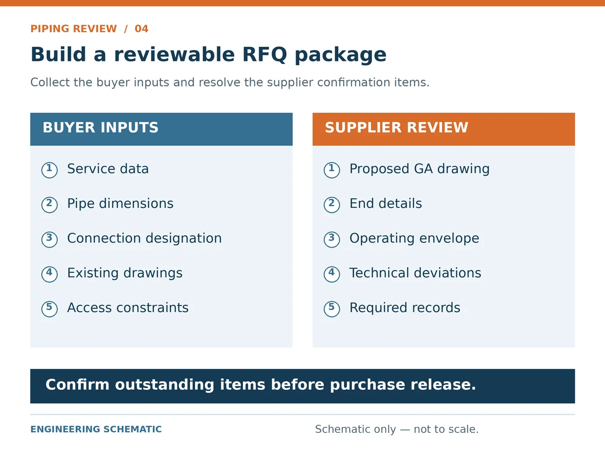
Submit the following information with the inquiry:
- Valve tag, quantity and isolation duty.
- Medium, composition, phase and relevant solids or contamination.
- Normal and design pressure/temperature, plus relevant operating cases.
- Nominal size, pipe dimensional standard, material, outside diameter and thickness.
- Piping class and complete end-connection designation.
- Required bore and any pigging or cleaning-tool requirement.
- Installed length, orientation and operating/maintenance space.
- Operating differential pressure, operating frequency and operator requirements.
- Body, trim, seat, packing and gasket requirements.
- Required shut-off performance, test conditions and acceptance basis.
- Applicable standards with contract editions, tests, inspection and documents.
- Existing valve drawings, field measurements and site photographs where available.
Request a supplier deviation list. Identify whether each critical field is confirmed, proposed or awaiting buyer input. Use the gate and globe valve datasheet resource to organize the technical inquiry.
Frequently Asked Questions
How do I match a gate valve to an existing pipe?
Check service suitability, pipe dimensions, the complete end designation, valve length and operating space. Record field installation space separately from the valve dimension, then compare the existing records and measurements with the proposed supplier drawing before approval. Does the same nominal size guarantee a compatible connection?
No. Nominal size does not confirm actual bore, flange facing and drilling, thread designation, weld-end preparation or valve length. Pressure class also needs a material, temperature and product-design basis; it is not a fixed allowable pressure. What dimensions are needed to replace a gate valve?
Record the valve face-to-face or end-to-end dimension with its specified reference planes, the separate field installation span, connection details, operating envelope and maintenance/removal space. Include drawing revisions and identify any unconfirmed measurements. Can NPT and BSP threaded connections be interchanged?
Do not specify them as interchangeable. Confirm the exact standard, mating-thread designations and sealing detail. ISO 7-1 addresses pressure-tight joints made on the threads; ISO 228-1 uses a seal outside the fastening threads. The label “BSP” alone is insufficient to approve a connection. Can a gate valve be installed in a vertical pipe?
Permission depends on the valve construction, size, operator, service and manufacturer instructions. Confirm the proposed arrangement on the supplier drawing and installation documentation. Does a full-bore gate valve automatically meet pigging requirements?
No. Confirm the tool envelope and the complete internal passage, including adjoining components. Request explicit evidence for the proposed configuration.
Request a Gate Valve Piping Compatibility Review
Send the medium, operating/design pressure and temperature, pipe size and wall thickness, complete connection designation, required shut-off basis and operating differential pressure. For replacement work, attach the existing drawing or marked-up site dimensions, access constraints and any unknown fields. Request that the proposed drawing and deviation list identify the items still requiring confirmation.
Submit your gate valve piping data to Raymon Valve for review of the proposed configuration and any remaining interface questions. Final selection requires the complete datasheet, applicable project requirements and manufacturer-confirmed documentation.
Engineering note: This guide supports piping compatibility screening and RFQ preparation. The diagrams are illustrative and are not approved product drawings. No specific valve model, load limit, installation orientation, welding detail or test arrangement is approved by this article.
Confirm the selected configuration using the complete datasheet, applicable contract editions, approved supplier drawings and model-specific installation instructions. The referenced standards describe particular dimensional or connection scopes; they do not establish certification of a supplied product. Factory records and site acceptance documents serve different purposes.
Standards reference note: Official publisher pages checked on 12 November 2026 displayed ASME B16.5-2025, B16.10-2022, B16.25-2022, B1.20.1-2013 (R2018), ISO 7-1:1994 and ISO 228-1:2000. These references support the scope explanations above. Use the contractually specified editions and approved project documents for dimensions and acceptance; public scope descriptions do not replace the full standards or establish product conformity.
Thread reference scopes: ISO 7-1 pressure-tight thread joints and ISO 228-1 fastening threads distinguish the two sealing routes described above. Confirm the complete mating designation and seal arrangement, not only the commercial label “BSP”.
Published by Raymon Valve. No named engineering reviewer or project-specific approval is asserted.
 English
 German
 Arabic
 French
 Spanish
 Italian
 Portuguese
 Russian