
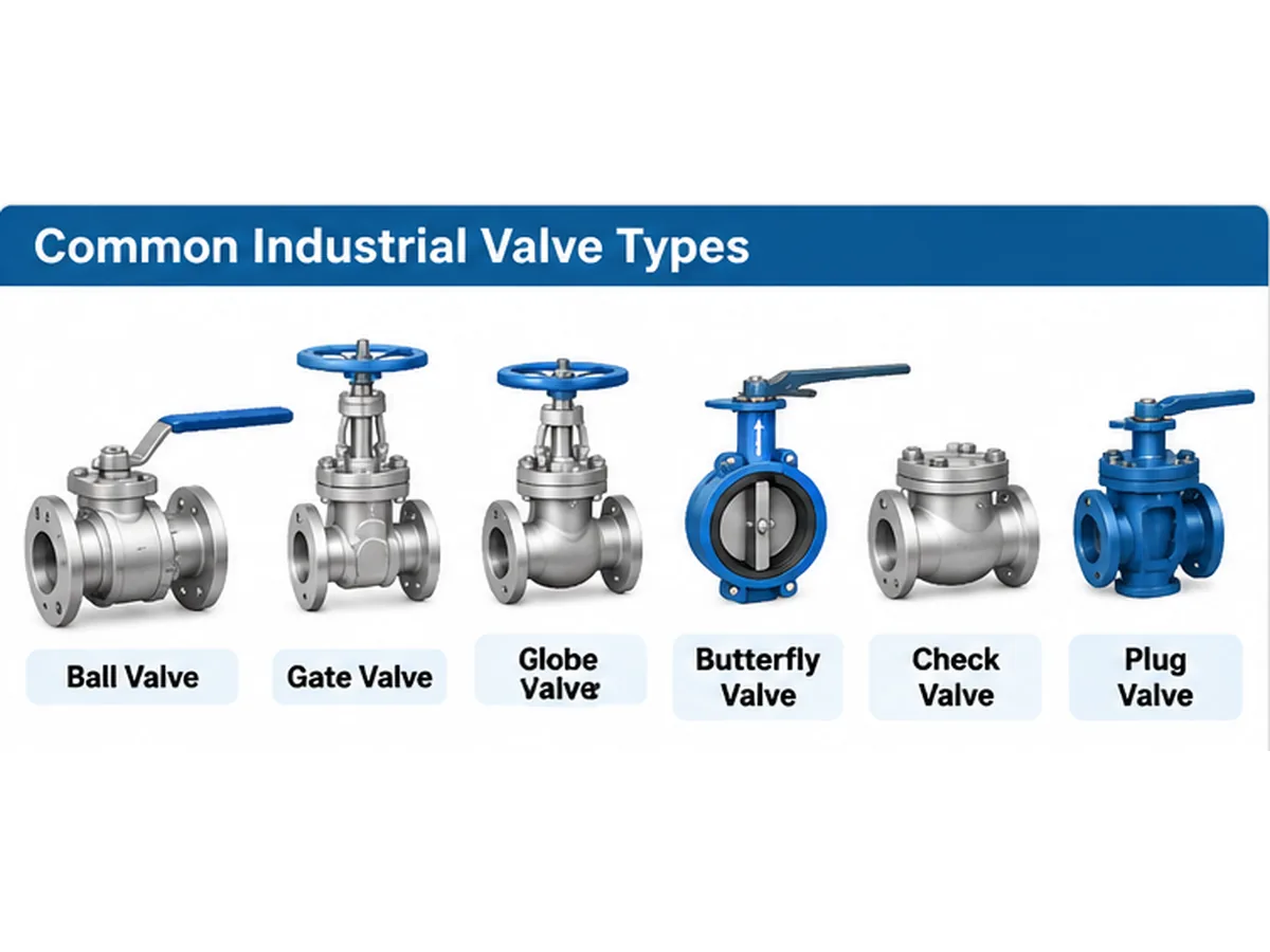
Industrial valve types are best classified by function, construction, motion and actuation. Ball, gate, globe and butterfly valves are commonly used for isolation or flow regulation; check valves restrict reverse flow, while control and pressure-control valves serve defined process duties. For engineers and procurement teams, the correct choice depends on the medium, flow conditions, design pressure and temperature, required shut-off or control performance, materials, connections and project specification—not nominal size alone. This guide compares the main designs and identifies the data needed for a defensible preliminary selection.
1. How Are Industrial Valves Classified?
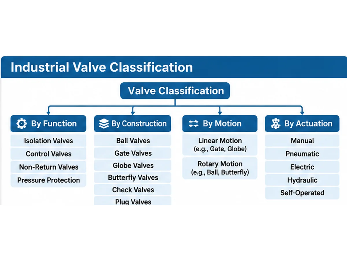
Industrial valves can be classified in several ways. The most useful classification methods are based on their primary function, internal construction, operating movement and actuation method. These categories overlap. For example, a pneumatic ball valve is a rotary-motion valve, an actuated valve and an isolation valve.
Quick classification: classify a valve first by what the process requires it to do—isolating, regulating, preventing reverse flow or controlling pressure. Then confirm the construction, materials, pressure-temperature rating, end connection and operating method. A single valve may belong to several categories at once.
1.1 Classification by Function
Isolation valves start or stop flow by opening or closing the flow passage. Common examples include ball valves, gate valves, butterfly valves and plug valves.
Control and throttling valves regulate flow by changing the effective flow area. Globe control valves, butterfly control valves and ball control valves are possible designs, depending on the required control characteristics and service conditions.
Non-return valves, also called check valves, allow flow in the intended direction while restricting reverse flow. Their closure behavior depends on flow velocity, differential pressure, installation orientation and internal design.
Pressure relief valves protect equipment and piping systems by releasing fluid when pressure reaches a specified condition. Their selection requires a review of the protected system, relieving capacity, medium and discharge arrangement.
Pressure reducing valves maintain a lower downstream pressure within a defined operating range. Selection depends on inlet pressure, required outlet pressure, flow range and control stability.
1.2 Classification by Construction
Common construction types include ball, gate, globe, butterfly, check, plug, diaphragm, pinch and needle valves. Each design has different flow characteristics, operating mechanisms and maintenance considerations.
1.3 Classification by Motion
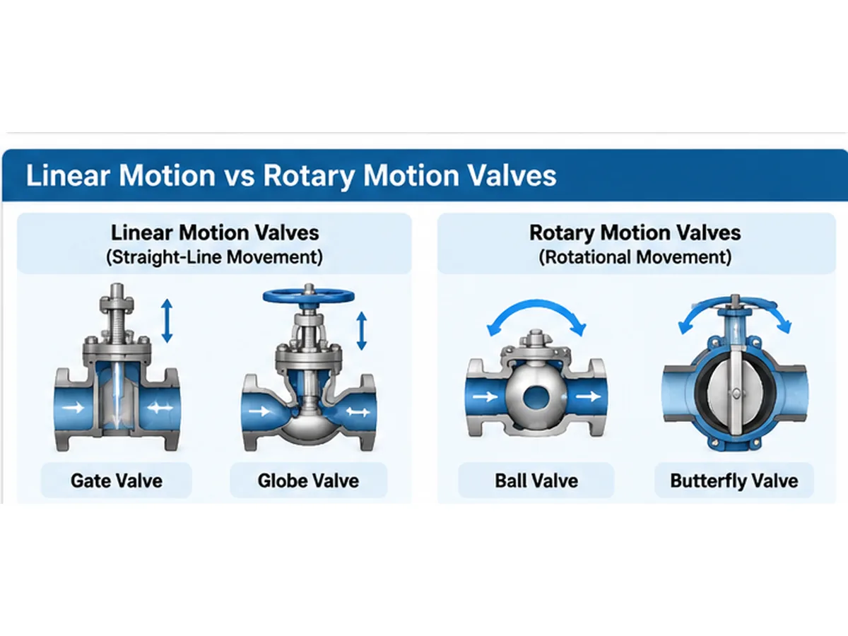
Linear-motion valves move a closure element along a relatively straight path. Gate, globe and diaphragm valves are examples. Rotary-motion valves use a rotating closure element; ball, butterfly and plug valves are common examples.
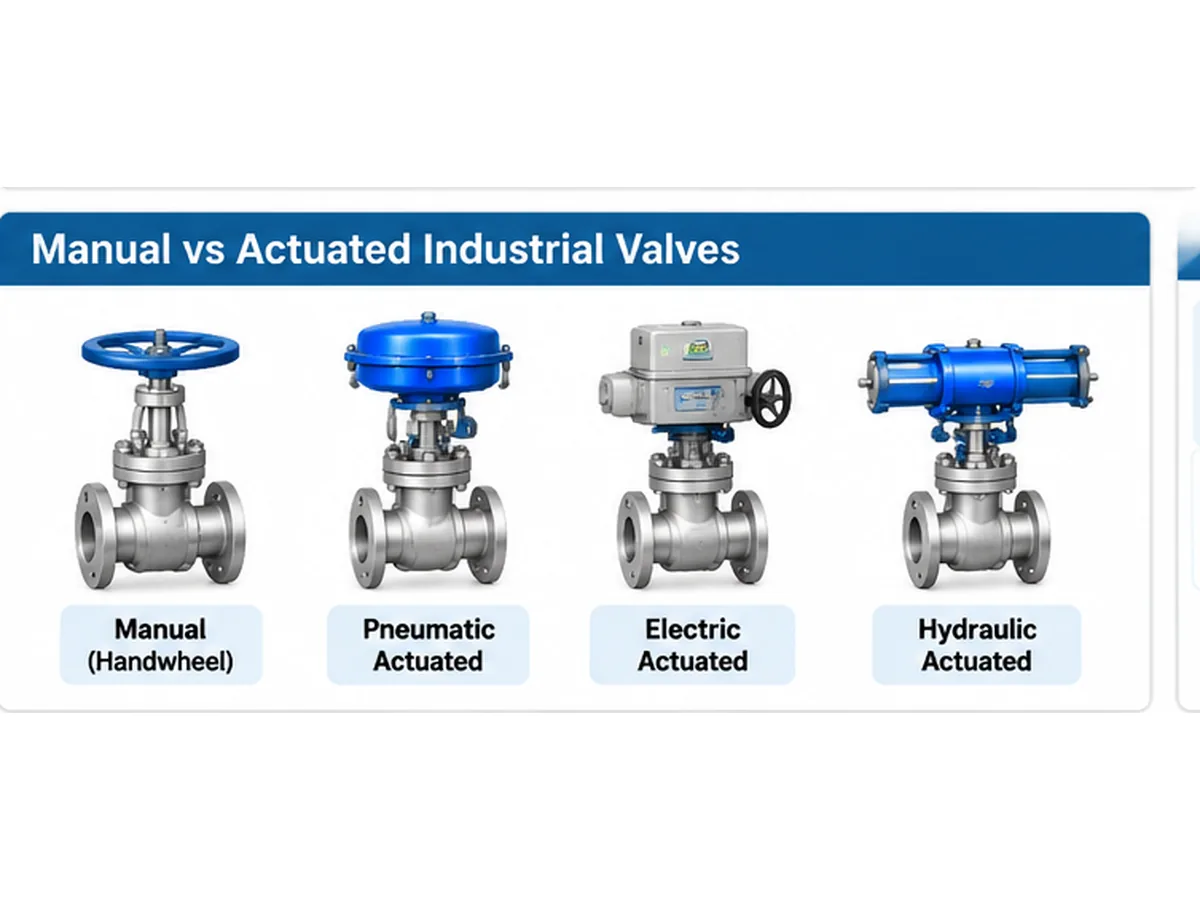
1.4 Classification by Actuation Method
- Manual: handwheels, levers or gear operators.
- Pneumatic: compressed air or gas operates the actuator.
- Electric: an electric motor operates the valve.
- Hydraulic: pressurized hydraulic fluid provides operating force.
- Self-operated: process pressure or an integrated mechanism provides the regulating action.
2. Main Types of Industrial Valves and How They Work
Understanding the construction and operating principle of each valve type is essential for preliminary equipment selection.
2.1 Ball Valves
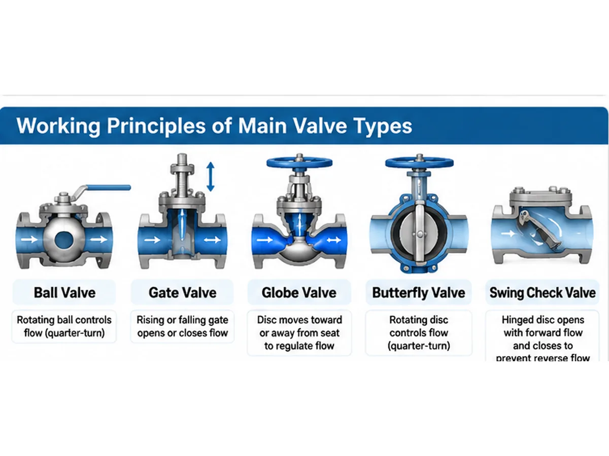
Ball valves use a spherical closure element with a through-hole. Rotating the ball aligns or misaligns the bore with the pipeline to control flow. Most conventional ball valves use quarter-turn operation.
Common configurations include floating ball and trunnion-mounted designs, as well as soft-seated and metal-seated arrangements. Ball valves are widely used for isolation and, in suitable designs, selected control duties.
Selection should consider seat material, differential pressure, temperature, operating torque, leakage requirements and medium compatibility.
2.2 Gate Valves
Gate valves control flow by moving a gate or wedge into or out of the flow passage. Common designs include solid wedge, flexible wedge, split wedge and parallel slide configurations.
Many gate valve designs provide a relatively unobstructed flow passage when fully open. They are primarily intended for on-off isolation and are generally unsuitable for continuous throttling, which can cause unstable flow, vibration or internal erosion..
2.3 Globe Valves
Globe valves regulate flow by moving a disc or plug toward or away from a stationary seat. Straight-pattern, angle-pattern and Y-pattern configurations are used for different installation and flow requirements.
Globe valves are commonly considered for throttling, but their flow path generally creates more pressure drop than comparable full-port isolation designs. Review trim geometry and operating differential pressure. Explore Raymon Valve globe valves.
2.4 Butterfly Valves
Butterfly valves use a disc mounted on a rotating shaft. Common configurations include concentric, double-offset and triple-offset designs.
Their compact construction and quarter-turn operation suit many pipeline applications. Disc geometry, seat material, pressure differential, temperature and required shut-off performance must be reviewed. The disc remains in the flow passage when fully open, which can influence pressure loss..
2.5 Check Valves
Check valves respond automatically to flow conditions to prevent or restrict reverse flow. Common designs include swing, dual-plate, axial and nozzle check valves.
Typical field-review scenario: A check valve may chatter at low flow even when its nominal size matches the line. Review the actual flow range, valve type, orientation and closure dynamics; line size alone does not demonstrate stable operation.
Selection must consider flow velocity, pressure differential, installation orientation, closure characteristics and potential water hammer. Explore Raymon Valve check valves.
2.6 Control Valves
Control valves regulate process variables by adjusting flow in response to a control signal. They may use globe, butterfly, ball or other application-specific constructions and may be equipped with pneumatic or electric actuators and positioners.
Typical RFQ review scenario: A control valve specified only by pipeline size may have unsuitable capacity or control characteristics. Request minimum, normal and maximum flow, upstream and downstream pressure, temperature, fluid properties, allowable pressure drop and the required control range before sizing or trim selection.
Control valve sizing requires process data such as flow rate, upstream and downstream pressure, temperature, fluid properties and allowable pressure drop. Cavitation, flashing, choked flow, noise and outlet velocity may also affect the design. A control valve should not be sized solely from nominal pipeline diameter. Explore Raymon Valve control valves.
2.7 Other Industrial Valve Types
Plug valves use a cylindrical or tapered plug with a flow passage. Diaphragm valves use a flexible diaphragm to control flow. Pinch valves compress a flexible sleeve and may be considered for certain slurry services. Needle valves use a tapered closure element for fine flow adjustment in small-bore systems. Each requires service-specific material and pressure-temperature review.
3. Linear Motion vs Rotary Motion Valves
| Comparison | Linear Motion | Rotary Motion |
|---|---|---|
| Movement | Straight-line movement | Rotational movement |
| Common types | Gate, globe, diaphragm | Ball, butterfly, plug |
| Operating mechanism | Stem movement | Rotating shaft |
| Typical duties | Isolation or regulation, depending on design | Isolation or regulation, depending on design |
| Design considerations | Stroke and stem arrangement | Rotation angle and operating torque |
Linear-motion designs may require vertical clearance depending on stem configuration. Rotary-motion designs use angular movement, which can simplify actuation in many applications. Motion type alone does not determine throttling suitability; internal construction and operating characteristics must also be evaluated.
4. Manual vs Actuated Industrial Valves
4.1 Manual Valves
Manual valves are operated by handwheels, levers or gear mechanisms. They are commonly used where remote operation or frequent automatic adjustment is not required.
4.2 Pneumatic Actuated Valves
Pneumatic actuators use compressed air or gas. Review supply pressure, actuator torque or thrust, operating time and required fail position.
4.3 Electric Actuated Valves
Electric actuators use a motor to operate the valve. Selection should consider power supply, operating time, control signal, position feedback and environmental conditions.
4.4 Hydraulic Actuated Valves
Hydraulic actuators use pressurized fluid to generate operating force. They may be considered where high operating forces or particular control arrangements are required.
4.5 Self-Operated Valves
Self-operated valves use process conditions or an integrated mechanism to perform a regulating function. Pressure regulators are a common example; suitability depends on available pressure, flow conditions and required control stability.
Actuator sizing note: Final actuator selection requires manufacturer-specific valve operating torque or thrust data, differential pressure, operating conditions, supply conditions and fail-action requirements. Do not size an actuator from valve nominal size alone.
5. Industrial Valve Types Used in Different Applications
| Application | Common Valve Types | Main Selection Consideration |
|---|---|---|
| Oil and gas pipelines | Ball, gate, check | Isolation and reverse-flow prevention |
| Chemical processing | Ball, globe, butterfly, lined valves | Chemical compatibility |
| Power generation | Gate, globe, check | Pressure and temperature |
| Water treatment | Butterfly, gate, check | Corrosion and flow conditions |
| Steam systems | Globe, gate, check | Pressure-temperature conditions |
| Slurry service | Pinch, lined and suitable severe-service designs | Abrasion and solids |
These are preliminary application directions, not universal recommendations. Final suitability depends on the actual medium, operating conditions, valve construction and project requirements.
6. Industrial Valve Types Comparison Table
| Valve Type | Primary Function | Motion | Main Limitation |
|---|---|---|---|
| Ball | Isolation / selected control duties | Rotary | Seat and torque requirements |
| Gate | Isolation | Linear | Generally unsuitable for continuous throttling |
| Globe | Regulation / isolation | Linear | Higher pressure drop |
| Butterfly | Isolation / selected control duties | Rotary | Disc and seat interaction |
| Check | Non-return | Automatic | Dynamic closure behavior |
| Control | Process regulation | Linear / rotary | Requires proper sizing |
| Plug | Isolation / diversion | Rotary | Torque and sealing requirements |
| Diaphragm | Isolation / selected control duties | Linear deformation | Diaphragm compatibility |
| Pinch | Isolation / selected control duties | Sleeve deformation | Sleeve compatibility and wear |
| Needle | Fine flow regulation | Linear | Limited flow capacity in many designs |
No single valve type is suitable for every industrial application. Selection depends on process conditions, valve construction, material compatibility, operating requirements and project specifications.
7. How to Choose the Right Industrial Valve Type
Step 1: Identify the Required Valve Function
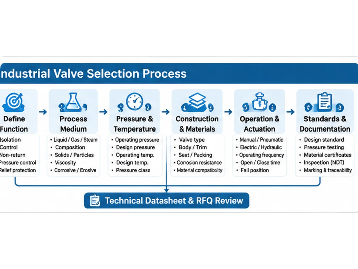
Determine whether the requirement is isolation, throttling, reverse-flow prevention, pressure reduction or overpressure protection. The required function establishes the initial range of suitable designs.
Step 2: Review the Process Medium
Identify whether the medium is liquid, gas or steam. Record chemical composition, concentration, solids, viscosity and potential corrosive or erosive characteristics.
Step 3: Confirm Pressure and Temperature
Review normal operating and design pressure, operating and design temperature, and required pressure class or PN. Pressure class alone does not establish complete operating suitability; applicable pressure-temperature ratings and material requirements must be confirmed.
Do not treat a Class designation or PN value as a universal pressure limit. The allowable rating depends on the applicable rating standard, material group, temperature and the exact valve construction. Check both normal operating and design conditions, including minimum temperature and any thermal cycling.
Step 4: Evaluate Valve Construction and Materials
Review body, closure element, seat, stem, trim, packing and gasket materials. Compatibility must be assessed against the actual process environment, including corrosion and erosion risks.
Step 5: Confirm Operation and Actuation
Determine manual or automated operation, frequency, opening and closing time, available power source, required torque or thrust and fail position. Final actuator sizing requires product-specific operating data.
Actuator selection also requires the valve manufacturer’s torque or thrust data over the relevant differential-pressure and service envelope, required operating time, operating frequency, supply conditions and fail action. Valve nominal size alone is not an actuator sizing basis.
Step 6: Review Standards, Testing and Documentation
Confirm applicable design and testing requirements, inspection and test plan, material traceability, NDT or PMI where specified, third-party inspection, marking and documentation. The applicable requirements depend on valve type, project specification, jurisdiction and intended service. See the valve standards resource and valve pressure testing resource.
| Document Type | What It Addresses | What the Buyer Should Confirm |
|---|---|---|
| Product / design standard | Product-specific design and construction requirements | Applicability to the exact valve type, size, class and service |
| Pressure-temperature rating | Allowable rating for defined materials and construction | Material group, temperature and governing rating standard |
| Dimensional / end-connection standard | Face-to-face, flange, thread or welding-end interfaces | Mating dimensions and project connection requirements |
| Inspection and pressure-test standard | Defined examination and pressure-test requirements | Test type, acceptance criteria, medium and witness points |
| Project specification and ITP | Project supplements, inspection stages and deliverables | Deviations, hold/witness points and required records |
Keep design requirements, pressure-temperature ratings, dimensional requirements and test requirements distinct. For example, ISO 5208:2015 addresses pressure testing of metallic industrial valves; it does not by itself establish that a valve design is suitable for a particular process duty. ASME B16.34 addresses specified construction and rating topics for valves within its scope. Confirm the applicable edition and product scope in the purchase specification.
8. Valve Selection Decision Matrix: Match the Function to the Service
Use the following matrix as a screening tool before selecting a valve construction. It identifies common starting points and the conditions that can change the decision. It is not a substitute for sizing, pressure-temperature verification or project approval.
| Required Duty | Common Starting Designs | Key Inputs to Confirm | Do Not Assume |
|---|---|---|---|
| Frequent on-off isolation | Ball, butterfly, plug | Cycle frequency, shut-off requirement, differential pressure, seat compatibility and operating torque | That every soft seat is compatible with the medium or temperature |
| Line isolation with a relatively clear full-open passage | Gate, full-port ball | Required bore, pigging or solids passage, face-to-face and installation envelope | That a gate valve is suitable for continuous throttling |
| Modulating flow control | Globe control valve, characterized butterfly or ball design | Minimum/normal/maximum flow, pressure drop, fluid properties, noise and cavitation/flashing risk | That nominal pipe size is sufficient for control valve sizing |
| Reverse-flow prevention | Swing, dual-plate, axial or nozzle check | Flow velocity, orientation, transient conditions, closing behavior and allowable pressure loss | That a check valve alone eliminates water hammer |
| Fine adjustment in small-bore service | Needle valve or purpose-designed metering valve | Required flow range, fluid cleanliness, pressure drop and connection size | That a needle valve is appropriate for high-capacity process control |
| Slurry or solids-bearing service | Pinch, suitable lined or slurry-service designs | Particle size, concentration, abrasiveness, settling, sleeve/lining material and maintenance access | That a general-purpose valve will tolerate abrasive solids |
Selection boundary: If the process data, required leakage class, transient conditions or material compatibility are unknown, shortlist candidate valve families only. Do not issue a final valve or actuator recommendation until the missing inputs are resolved.
9. Material, Seat and Sealing Review
Valve material selection is a component-level review, not simply a choice of body material. The body, closure element, stem, seat, packing and gasket may experience different combinations of pressure, temperature, chemical exposure, friction and erosion.
| Component | What to Review | Useful RFQ Information |
|---|---|---|
| Body and bonnet | Pressure-temperature rating, corrosion allowance where applicable, process compatibility and design material specification | Material grade, design conditions, corrosion environment and applicable material standard |
| Ball, disc, gate or plug | Strength, wear, erosion, coating or overlay requirements and compatibility with the process medium | Trim material, hardness or surface treatment requirements where specified |
| Seat and sealing surfaces | Temperature, differential pressure, shut-off target, solids, abrasion and chemical compatibility | Seat type/material, leakage requirement and test basis |
| Stem and shaft | Strength, corrosion, stress, wear and packing interface | Material grade, anti-blowout or retention requirements where applicable |
| Packing and gasket | Temperature, fluid compatibility, emissions requirements and pressure boundary conditions | Packing/gasket material, emissions or leakage specification and documentation |
For corrosive, sour, oxygen, hydrogen, cryogenic or other special services, the material review may require additional environmental limits, cleanliness controls, qualification evidence or project-specific restrictions. A generic material name alone is not enough to establish suitability.
10. Common Selection and Installation Risks
| Potential Issue | Possible Contributing Factor | What to Verify |
|---|---|---|
| Seat leakage after commissioning | Incorrect seat material, debris, installation damage, unsuitable differential pressure or wrong test expectation | Seat specification, cleanliness, installation procedure, pressure differential and agreed leakage test basis |
| High operating torque | Pressure loading, seat friction, deposits, packing load, temperature or actuator margin assumptions | Valve torque data over the operating envelope, differential pressure and actuator sizing basis |
| Excessive vibration or noise | High local velocity, unsuitable throttling design, cavitation, flashing or aerodynamic noise | Process calculations, valve sizing, trim selection, piping arrangement and noise criteria |
| Check valve slam or transient pressure | Reverse flow develops before closure, unsuitable dynamic response or poor system arrangement | Flow profile, pump trip scenario, closing characteristics and system transient analysis where required |
| Premature internal wear | Solids, erosion, corrosion, repeated throttling or operation outside intended range | Medium composition, particle loading, velocity, material selection and duty cycle |
| Actuator or access conflict | Insufficient clearance, wrong orientation, cable/air routing or maintenance envelope | GA drawing, actuator envelope, access for operation and removal, and installation orientation |
These are review prompts rather than diagnoses. Actual failure mechanisms should be confirmed using operating records, inspection findings, process data and component examination.
11. Supplier Technical Evaluation: What Evidence Should Be Reviewed?
When comparing valve quotations, procurement teams should normalize the technical scope rather than compare price and nominal size alone. Ask each supplier to identify deviations, exclusions and assumptions against the same datasheet and project specification.
| Evaluation Area | Evidence or Document to Request | Review Question |
|---|---|---|
| Design and configuration | Technical datasheet, GA drawing, sectional drawing and design-standard declaration | Does the offered construction, bore, rating and end connection match the requisition? |
| Materials | Bill of materials, material specifications and applicable material test certificates | Are pressure-boundary and wetted component materials clearly identified and traceable as required? |
| Testing and inspection | Inspection and test plan, pressure-test procedure and inspection records as contractually required | Are test type, acceptance criteria, witness points and documentation aligned with the purchase specification? |
| Special service qualification | Relevant qualification or test evidence when specified by the project | Does the evidence cover the offered design, materials, size, pressure class and service conditions? |
| Actuation | Actuator datasheet, sizing calculation/basis, power and control details, wiring or pneumatic schematic | Are operating loads, supply conditions, fail action and interfaces addressed? |
| Quality and traceability | Quality plan, identification/marking details, traceability records and final manufacturing record book index | Can the required inspection and documentation scope be demonstrated for this order? |
| Commercial deviations | Deviation list, exclusions, delivery scope and document schedule | Are all technical and commercial exceptions visible before bid comparison? |
Evidence should be relevant to the specific offered product and purchase order. A general company brochure or a certificate unrelated to the quoted valve does not establish compliance with a project requirement.
12. Industrial Valve RFQ Checklist
A complete request for quotation should provide sufficient information for a manufacturer to review the proposed valve construction. Where applicable, include minimum, normal and maximum flow, design and operating pressure/temperature, medium composition, solids, leakage or control requirements, connection details, actuation and required inspection documentation.
- Valve type and required function
- Nominal size and quantity
- Pressure class or PN
- End connection and applicable design standard
- Process medium and composition
- Normal operating and design pressure
- Normal operating and design temperature
- Flow rate where relevant and required shut-off or control performance
- Body, trim, seat, stem, packing and gasket materials
- Corrosion, erosion and solids considerations
- Manual or actuated operation and actuator power source
- Operating frequency, opening/closing time and fail position where applicable
- Pressure testing, inspection and documentation requirements
- Material certificates, NDT, PMI and third-party inspection where specified
- Required GA drawings, sectional drawings, datasheets and document schedule
- Inspection and test plan, acceptance criteria and witness/hold points
- Supplier deviation list, exclusions and technical assumptions
Providing these details helps suppliers evaluate the technical scope and identify missing information before quotation.
13. Frequently Asked Questions About Valve Types
What are the main types of industrial valves?
Common industrial valve types include ball, gate, globe, butterfly, check, plug, diaphragm, pinch and needle valves. Pressure relief and pressure reducing valves serve additional process functions.How many types of valves are there?
There is no single fixed number because classification depends on construction, function, movement and operating mechanism. Common designs include ball, gate, globe, butterfly, check, plug, diaphragm, pinch and needle valves.What are the five basic types of valves?
Five widely recognized industrial valve types are ball, gate, globe, butterfly and check valves. They serve different purposes, including isolation, flow regulation and reverse-flow prevention.What is the difference between gate valves and globe valves?
Gate valves are primarily designed for on-off isolation, while globe valves are commonly used for flow regulation and throttling. Their internal flow paths and closure mechanisms influence pressure drop and operating characteristics.Which valve types are used for flow control?
Globe valves, control valves, butterfly valves and certain ball valve designs can be used for flow regulation. Selection depends on control accuracy, flow characteristics, pressure drop and operating conditions.What is the difference between linear and rotary valves?
Linear valves use straight-line movement of the closure element, while rotary valves use rotational movement. Gate and globe valves are typical linear designs; ball and butterfly valves are common rotary designs.Which valve is best for high-pressure applications?
There is no universally best valve for high-pressure service. Ball, gate and globe valves may be suitable in different applications depending on pressure-temperature requirements, construction, material, sealing design and applicable standards.How do I choose the right industrial valve for my application?
Start with the required function, process medium, operating and design pressure, temperature, flow conditions and shut-off performance. Then evaluate construction, material compatibility, end connections, actuation and testing requirements. A complete technical datasheet is necessary for final selection.
14. Conclusion: Selecting the Right Industrial Valve
Industrial valve selection begins with understanding the required function and operating conditions of the process system. Ball, gate, globe, butterfly and check valves serve different purposes, while plug, diaphragm, pinch and needle valves address more specialized requirements.
The correct selection depends on valve construction, process medium, pressure, temperature, materials, operating method and project specifications. For additional industrial valve technical resources, review the related engineering guidance and confirm each recommendation against the project datasheet. For EPC contractors, engineers and procurement teams, a complete technical datasheet is the starting point for evaluating suitable designs and obtaining comparable quotations.
Need Help Selecting the Right Industrial Valve?
Share your valve function, medium, nominal size, pressure class, design pressure, temperature, material requirements, end connections, actuation method and inspection/documentation scope with Raymon Valve. Include the datasheet or project specification where available so the technical scope, assumptions and open items can be reviewed.Request a Valve Selection Review
Engineering Note: This article provides general industrial valve classification and preliminary selection guidance. It does not replace project-specific engineering calculations, manufacturer datasheets, applicable standards or approved purchase specifications. Final valve selection must be confirmed against complete process conditions and project requirements.
Author: Raymon Valve Technical Content Team.
 English
 German
 Arabic
 French
 Spanish
 Italian
 Portuguese
 Russian