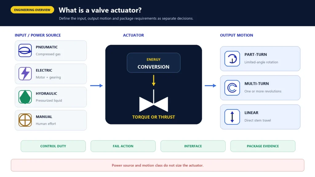
Overview of pneumatic, electric and hydraulic valve actuator types

What Is a Valve Actuator? Types, Working Principles and Selection Inputs

A valve actuator is the device or mechanism that supplies the torque or thrust needed to move a valve to a required position. It converts pneumatic, electrical, hydraulic or manual input into rotary or linear movement at the valve stem or shaft. An actuator may provide simple open/close movement or controlled intermediate positioning, but a complete automated assembly also depends on mounting hardware, controls, feedback, accessories and a verified valve-load basis. Valve size and pressure class alone are not enough to select the actuator.

That distinction matters during an RFQ. The valve controls or isolates the process fluid; the actuator provides movement and force; and the complete package must connect those functions without losing mechanical margin, control compatibility or the required response to a utility failure.

Engineering boundary: This guide explains principles and procurement inputs. It does not size an actuator or establish product-specific capability.

How Does a Valve Actuator Work?

At principle level, an actuator follows this chain:

Command or manual input -> energy conversion -> mechanical mechanism -> torque or thrust -> valve stem or shaft travel -> valve position -> feedback, where specified

The input may be compressed air, electrical power, hydraulic pressure or manual effort. Inside the actuator, a piston, diaphragm, motor, gear train, screw mechanism or similar arrangement converts that input into useful movement. Rotary actuators deliver torque to a shaft. Linear actuators deliver thrust through a defined stroke. Some multi-turn arrangements must transmit torque while also accommodating axial thrust at the valve interface.

End stops, torque or thrust limiting, position indication and feedback may help control travel, but their presence and function are product-specific. Moving the stem to a nominal end position does not by itself prove seat leakage, control accuracy or process suitability. Those outcomes also depend on the valve construction, service conditions, adjustment, controls and agreed test criteria.
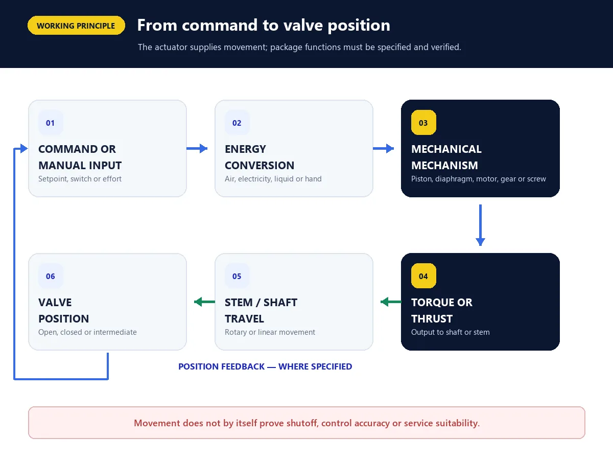
Diagram showing how a valve actuator converts a command and energy input into valve movement
Signal-to-motion chain: the actuator converts an input into torque or thrust, while the complete package determines control and feedback behavior.

Valve Actuator Types by Output Motion

Power source and output motion are separate classifications. An actuator can be electric and part-turn, pneumatic and linear, or hydraulic and rotary. The first screening question is therefore not simply “electric or pneumatic?” It is “what movement and load must the valve receive?”

Output motionWhat it doesCommon valve arrangementsData still required
Part-turn / quarter-turnRotates through a limited angleBall, butterfly and plug valvesValve torque profile, travel angle, maximum differential pressure, direction, seat condition and interface
Multi-turnDelivers one or more output-shaft revolutionsGate, globe and gearbox-operated arrangementsRequired turns, torque, possible thrust, stem/interface details, travel limits and speed
LinearProduces direct stem travel and thrustSliding-stem control valves and other linear arrangementsStroke, thrust in each direction, spring/load behavior, mounting geometry and control duty

These are common pairings, not universal sizing rules. A valve type name does not establish its operating load, and a nominal travel description does not confirm the exact mounting or output interface.

Part-Turn and Quarter-Turn Actuators

Part-turn actuators rotate a valve shaft through less than a complete revolution. Many ball and butterfly valves use travel close to a quarter turn, but the required angle and stop arrangement must come from the exact valve and assembly design.

For a pneumatic rack-and-pinion design, pressure acts on pistons and moves linear racks. The racks rotate a pinion connected to the valve shaft. A scotch-yoke design uses different geometry to convert piston travel into rotation, so its output pattern across the stroke can differ from a rack-and-pinion unit. The actuator must be checked against the valve's relevant torque requirements throughout travel, not only against one headline torque value.

Multi-Turn Actuators

A multi-turn actuator rotates its output through one or more revolutions. Gate and globe valve arrangements may require many turns between open and closed positions. The assembly may also need to manage stem thrust, a rising stem, a gearbox or a particular drive connection.

Required turns, seating/unseating behavior, allowable stem load, travel speed and end-of-travel control should therefore be documented. Selecting a multi-turn actuator from valve size alone can miss both the mechanical interface and the most demanding operating point.

Linear Actuators

Linear actuators move a stem over a specified stroke. Pneumatic diaphragm or piston actuators are familiar examples, but electric and hydraulic mechanisms can also produce linear output.

The review must identify required thrust in both directions, available stroke, spring contribution where present, mounting alignment and the intended control function. For a modulating control valve, actuator selection is only one part of the wider valve-sizing and control-performance calculation; line size and pressure class do not establish Cv/Kv, stability, noise, cavitation or flashing behavior.
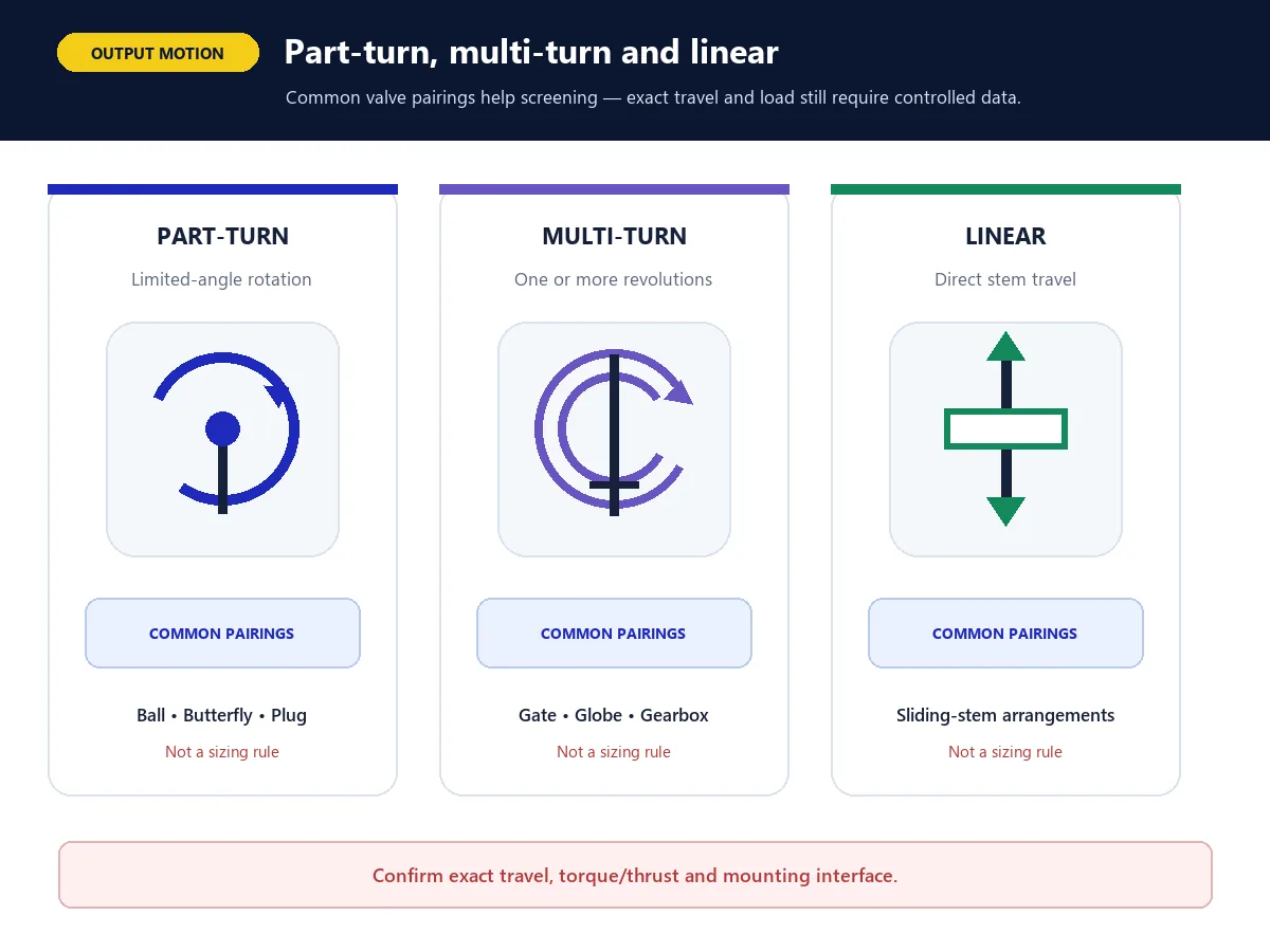
Comparison of part-turn, multi-turn and linear valve actuator output motion
Output-motion classification: part-turn, multi-turn and linear arrangements require different load and interface data.

Valve Actuator Types by Power Source

Pneumatic Actuators

Pneumatic actuators convert compressed gas pressure into piston or diaphragm movement. The output may remain linear or be converted into rotary motion. Common configurations include double-acting designs, which use pressure to drive movement in both directions, and single-acting designs, which combine pressure-driven travel with a spring or other stored-energy arrangement.

A pneumatic actuator RFQ should define the minimum available supply pressure, supply quality, operating frequency, required travel time, exhaust or venting requirements, fail action and accessories. A spring-return label does not fully define the safe state: the valve load, spring orientation, control circuit, process forces and verified package behavior still matter.

Pneumatic equipment should not be described as universally suitable for hazardous areas. The exact actuator, solenoid, switches, positioner and other electrical or mechanical accessories must meet the project environment and documentation requirements.

Electric Actuators

An electric actuator uses a motor and a gear, screw or related mechanism to move the valve. Depending on the design, it may provide part-turn, multi-turn or linear output and may be configured for on-off or modulating duty.

Selection inputs include power supply, required torque or thrust, duty and operating frequency, travel time, control signal, local controls, indication, enclosure/environment, manual override and required protection functions. Torque or thrust limiting can protect the assembly when correctly configured, but it does not replace a verified sizing basis.

An electric actuator does not automatically move to a safe position during loss of power. It may stop, hold, move through a separate stored-energy arrangement or respond according to another package design. The required de-energized state and the means of achieving it must be specified and verified.

Hydraulic and Electro-Hydraulic Actuators

Hydraulic actuators use pressurized liquid to create linear force or rotary torque. Electro-hydraulic arrangements combine electrical control or power functions with a hydraulic circuit. These options can be useful where the required force, stored-energy arrangement, control architecture or site utility favors hydraulic power, but they are not an automatic “best” choice for a particular valve size or industry.

The engineering review should cover hydraulic supply and minimum pressure, fluid specification, accumulator or spring arrangement where used, leakage containment, temperature, maintenance access, control logic and fail action. Self-contained and centrally supplied systems have different package boundaries and maintenance implications.

Manual Operators and Overrides

A lever, handwheel or gearbox converts human effort into valve movement. A manual override can also be incorporated into a powered actuator package. It is an operating feature, not a substitute for lockout, isolation or the site's approved operating procedure.

Limit switches are not manual actuators. They indicate or signal position. Likewise, a solenoid valve and a positioner perform control functions but do not replace the actuator that supplies the mechanical output.

On-Off, Inching and Modulating Duty Are Different

An actuator's control duty affects its mechanical and electrical demands:

  • On-off duty: the valve normally moves between defined open and closed positions.
  • Inching or positioning duty: the valve is occasionally moved to an intermediate position.
  • Modulating duty: the valve repeatedly changes position in response to a control demand.
  • Continuous modulating duty: the actuator may be expected to make very frequent or continuous position corrections; only a product specifically supported for this duty should be offered.

The duty description influences starts, thermal loading, wear, control response and accessory selection. For modulating service, signal compatibility, feedback, deadband, hysteresis, resolution and dynamic response can affect loop performance. These values must come from the exact offered model and approved data; a generic actuator category cannot supply them.

A positioner compares the requested position with actual valve travel and adjusts actuator input. A solenoid valve can switch or route pneumatic or hydraulic control fluid. Limit switches provide discrete position signals. A digital controller may add diagnostics and communications. The quotation should identify each item separately.

What Makes Up an Actuated Valve Package?

An actuated valve package is more than an actuator mounted above a valve. Depending on the project, its controlled scope may include:

  1. valve body, trim, closure member, stem or shaft;
  2. actuator;
  3. mounting bracket, adapter, coupling and fasteners;
  4. gearbox or thrust unit where used;
  5. solenoid valve or electric motor-control arrangement;
  6. positioner or controller for positioning/modulating duty;
  7. limit switches and position indication;
  8. filter regulator, tubing and fittings for a pneumatic assembly;
  9. local controls and manual override;
  10. wiring terminals, cable entries, enclosure and environmental interfaces;
  11. assembly, setting, functional test and documentation scope.

A photograph showing these items does not prove that they are included in an offer. The commercial scope should be tied to an approved bill of materials, drawings and the quotation's inclusions and deviations. Exact package evidence should remain with the relevant valve actuator package record.
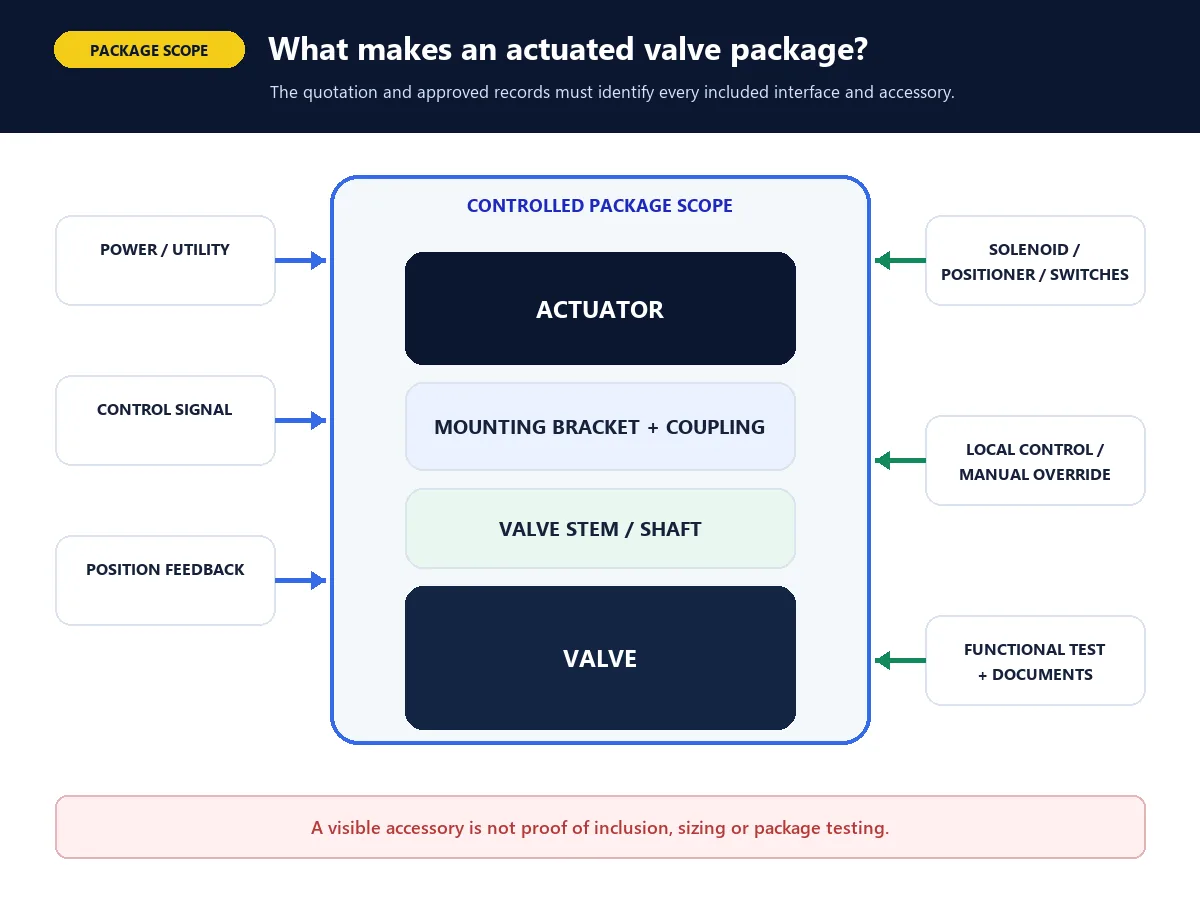
Actuated valve package boundary showing valve, actuator, mounting and control accessories
Package boundary: visible components do not prove quoted scope; inclusions must be tied to the approved offer and records.

Pneumatic vs Electric vs Hydraulic: What Changes the Decision?

Decision factorPneumatic routeElectric routeHydraulic / electro-hydraulic route
UtilityConfirm minimum gas pressure, quality and capacityConfirm voltage, phase/frequency or DC supply, available power and controlsConfirm hydraulic pressure, fluid, power unit and stored-energy arrangement
Valve loadMatch output across travel at minimum supplyMatch torque/thrust and duty at stated electrical conditionsMatch output across travel at minimum hydraulic condition
Fail actionDefine spring or stored-gas/control behaviorDefine stop/hold or separate stored-energy/backup architectureDefine spring, accumulator or powered response
SpeedSpecify required travel time and review air capacity/exhaustSpecify travel time and motor/duty limitationsSpecify travel time and hydraulic flow/control limits
Control dutyDefine on-off, positioning or modulating accessoriesSelect a product supported for the required duty and startsDefine servo/control architecture and required duty
EnvironmentVerify the complete accessory packageVerify exact enclosure and electrical/environmental evidenceReview fluid, seals, leakage containment and environment
MaintenanceConfirm air treatment, tubing and accessory supportConfirm electrical/gear/control supportConfirm hydraulic-fluid and power-unit maintenance capability

This table structures the questions; it does not select a winner. Site utilities, safe-state requirements, valve load, operating frequency, environmental constraints, controls and lifecycle support determine which route is appropriate.

Why Valve Size and Pressure Class Do Not Size the Actuator

Two valves with the same nominal size and class can require different operating torque or thrust. Relevant causes may include:

  • valve design and manufacturer geometry;
  • maximum differential pressure and flow direction;
  • seat loading, seal construction and shutoff requirement;
  • stem, packing and bearing friction;
  • temperature and material behavior;
  • deposits, fouling, corrosion or wear allowances defined by the project;
  • break-to-open, running and end-to-close load points;
  • spring or fail-action configuration;
  • minimum utility supply;
  • the required sizing factor and project calculation method.

The supplier should identify the source and process basis of the valve-load data, then compare the actuator's available output at the relevant travel position and minimum supply condition. For a more detailed input framework, use the actuator selection guide or request an actuator torque and thrust review.

No general article can replace a model-specific calculation or the responsible engineer's approval.

Minimum Inputs for Actuator Matching

An RFQ should make the following items explicit.

Valve and Process Data

  • valve type, manufacturer and model where known;
  • DN/NPS, rating route and end connection;
  • medium, composition and phase;
  • normal and design pressure and temperature;
  • normal and maximum differential pressure, including direction and abnormal cases;
  • model-specific torque or thrust data with source and load points;
  • required shutoff or control duty;
  • operating frequency and expected cycling.

Actuator and Control Requirements

  • available power source and minimum supply condition;
  • required fail-open, fail-close, fail-in-place or other defined safe state;
  • required travel time;
  • on-off, inching, positioning or modulating duty;
  • control signal and communication requirements;
  • local/remote controls and position indication;
  • positioner, solenoid, switches and accessory scope;
  • ambient temperature, ingress, corrosion and hazardous-area requirements;
  • mounting interface, available space and orientation;
  • sizing factor and calculation owner.

Quality and Order Scope

  • assembly and functional test requirements;
  • inspection and witness points;
  • approved drawings and wiring/pneumatic diagrams;
  • sizing calculation and assumptions;
  • manuals, certificates and project document list;
  • quantity, tag numbers, destination and deviation schedule.
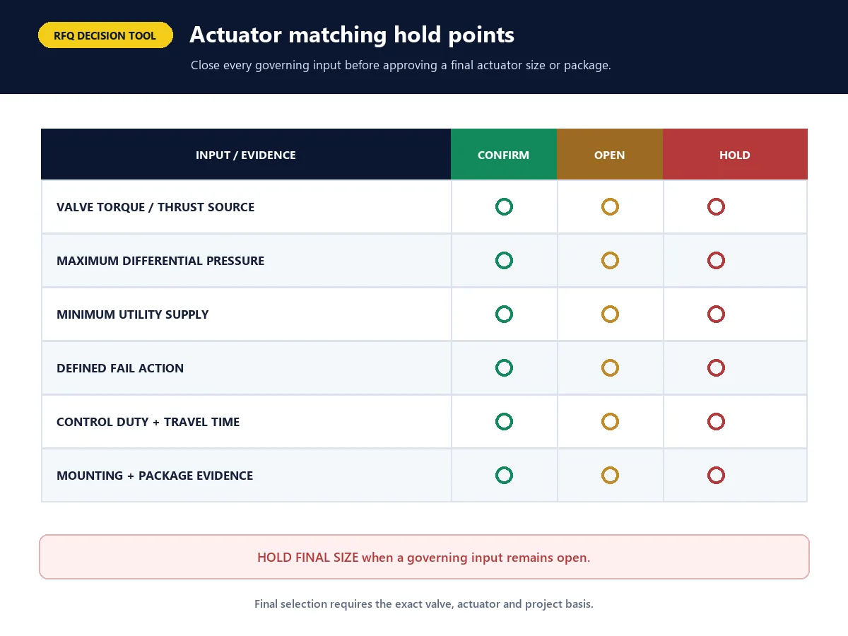
Valve actuator RFQ hold points for load, supply, fail action, interface and evidence
RFQ hold points: do not close actuator matching until load, supply, fail action, interface, controls and evidence are defined.

Evidence Buyers Should Request Before Approval

Decision to closeMinimum evidence to requestHold the decision when...
Valve operating loadModel-specific torque/thrust data with process assumptions and load pointsThe value comes only from size/class or an unidentified catalogue
Actuator available outputManufacturer output data at minimum specified supply and relevant travel positionsOnly nominal or maximum-supply output is shown
Sizing marginTraceable worksheet with project sizing factor and assumptionsThe margin or calculation owner is missing
Fail actionDefined spring/stored-energy/control architecture and functional verification“Spring return” or “fail safe” is stated without package logic
Mechanical interfaceApproved assembly drawing, stem/coupling and mounting detailsThe actuator and valve are listed separately without an interface check
Controls and accessoriesApproved bill of materials plus wiring or pneumatic schematicThe quotation uses “complete accessories” without itemization
EnvironmentExact offered-model ratings and required installation-area evidenceA general certificate or family brochure is used for every configuration
Package functionAgreed functional test procedure and acceptance recordIndividual component data are offered without package verification

Normalize Technical Bids Before Approving the Actuator Package

Actuator proposals are comparable only when suppliers return the same fields on the same operating basis. Mark each field as Confirmed, Partial, Open or Not Applicable. A critical Open field is a hold point, not permission to infer suitability from actuator type, valve size or catalogue output.

Confirmed — controlled source availablePartial — incomplete evidenceOpen — approval hold pointNot Applicable — reason recorded
Normalization fieldRequired supplier returnComparison ruleHold point
Offered identity and boundaryValve, actuator, mounting kit, gearbox/thrust unit, controls, accessories and exact model numbersCompare the complete offered package and stated exclusions“Complete package” is used without model-level itemization
Valve-load basisTorque or thrust at relevant travel/load points, governing differential pressure, direction, temperature and sourceUse controlled valve data for the governing process casesLoad is inferred from valve size/class or comes from an unidentified catalogue
Actuator-output basisOutput across relevant travel at minimum specified pneumatic/hydraulic supply or stated electrical conditionCompare available output with required load using the agreed sizing methodOnly maximum-supply or headline output is returned
Fail-action architectureRequired safe state, spring/accumulator/backup/control logic and reset behaviorReview the response of the complete valve-actuator-control systemA type label such as spring return or electric is treated as proof of fail position
Interface and travelStem/shaft details, coupling, bracket, mounting standard where applicable, stroke/angle/turns, stops and orientationCheck the approved assembly drawing and allowable loadsValve and actuator are listed separately without interface verification
Duty, controls and environmentOn-off/inching/modulating duty, frequency, travel time, signal, feedback, accessories, ambient and area requirementsCompare exact offered-model capability and accessory scopeGeneral family data or a single enclosure label is applied to every configuration
Tests, records and deviationsSizing worksheet, drawings, schematics, BOM, settings, functional test, certificates/reports and deviation scheduleSeparate component evidence from assembled-package acceptanceRequired documents, tests, acceptance criteria or deviations are ambiguous

For each Confirmed field, record the source document, revision, date and responsible reviewer. Procurement can then normalize technical scope before comparing price or delivery.

Approval Hold Points: When Actuator Matching Must Stop

Pause approval and obtain controlled evidence when any of the following applies:

  • model-specific valve torque or thrust is missing, lacks governing process assumptions or omits relevant load points;
  • actuator output is not stated for the minimum available supply and relevant travel position;
  • the requested safe state is not connected to a defined spring, stored-energy, backup-power or control architecture;
  • travel, coupling, bracket, stem/shaft load or mounting geometry is not verified on an approved assembly drawing;
  • duty, operating frequency, travel time, control signal or accessory responsibility is unresolved;
  • hazardous-area, ingress, corrosion, ambient or other environmental wording is not supported for every offered component that requires it;
  • sizing factor, calculation owner, package test, required records or technical deviations remain Open.

An Open hold point can be closed only by the responsible project party using controlled model data, an approved calculation, drawings, an agreed test or other scope-specific evidence. A general article, family brochure or component photograph cannot close it.

Common Actuator Selection Mistakes

The most common mistakes are often specification gaps rather than hardware defects:

  • selecting from valve size and pressure class only;
  • using normal rather than worst-case differential pressure;
  • sizing at nominal rather than minimum available supply;
  • assuming actuator type alone defines the safe state;
  • confusing actuator, positioner, solenoid and limit-switch functions;
  • omitting travel time, operating frequency or duty cycle;
  • failing to review the bracket, coupling and stem interface;
  • treating a general enclosure or certification label as universal suitability;
  • leaving package tests and documentation undefined;
  • assuming that a photographed actuator and accessory set is included.

A technically comparable bid should identify inclusions, exclusions, assumptions and deviations. A lower price is not a technical saving if the offer omits the required fail-action architecture, mounting scope, accessories, tests or records.

Practical Next Step

Use this five-step path:

  1. Define the valve duty and the required safe state.
  2. Obtain controlled valve torque or thrust requirements for the governing process cases.
  3. Define the minimum utility supply, travel time and control duty.
  4. Select and document the actuator, mounting and accessory package.
  5. Verify interface, output margin, settings, package function and required records.

Request Actuator Matching Support

Send the valve datasheet, maximum differential pressure, torque/thrust basis, minimum utility supply, fail action, travel time, control signal, accessory list, installation environment and documentation requirements through the Raymon Valve contact page. Ask for the returned comparison to state the exact offered models, calculation basis, sizing factor, assumptions, exclusions, Open fields and technical deviations.

The preliminary review can identify missing inputs and comparison points. Final package selection remains subject to the project specification, the exact offered equipment, controlled manufacturer data and responsible technical approval.

Request actuator matching support

Frequently Asked Questions

What does a valve actuator do?

It supplies the torque or thrust required to move a valve to a commanded position. Actual shutoff, control response and service suitability depend on the complete valve, actuator, controls and operating conditions.

What are the main types of valve actuators?

By power source, common groups include pneumatic, electric, hydraulic/electro-hydraulic and manual arrangements. By output motion, actuators may be part-turn, multi-turn or linear. Both classifications are needed to describe an application.

Is a solenoid valve the same as a valve actuator?

No. A solenoid valve can switch or direct pneumatic or hydraulic control fluid. It is normally a control accessory within the actuated package; the actuator provides the mechanical torque or thrust.

Is a valve positioner an actuator?

No. A positioner compares the requested and actual valve position and adjusts the actuator input. The actuator remains the component that supplies the movement and force.

Can an actuator be selected from valve size and pressure class?

No. Model-specific torque or thrust, governing differential pressure, travel, minimum utility supply, fail action, duty, operating frequency, environment and sizing margin are also required.

What is the difference between single-acting and double-acting pneumatic actuators?

A double-acting arrangement normally uses pneumatic pressure to drive movement in both directions. A single-acting arrangement normally combines pressure-driven travel in one direction with a spring or other stored-energy return. The actual fail position must be defined and verified for the complete assembly.

Does an electric actuator automatically fail closed during a power loss?

No. Its response depends on the exact actuator and package design. It may stop or hold, or it may use a spring, battery, capacitor, hydraulic accumulator or another stored-energy/backup arrangement to reach a defined position.

What information should be sent with an actuator RFQ?

Send the valve model and load data, service and maximum differential pressure, minimum available utility, fail action, travel time, control duty and signal, accessories, environment, mounting details, quantity and required tests/documents.

Sources and Reference Scope

These primary sources support general actuator terminology, specification fields and the need to compare valve load with available actuator output. They are reference-only context. Their inclusion does not state that a Raymon Valve product is designed, tested, compliant or certified to an ISA document, and it does not replace the current project specification or exact-model evidence.

Applicability note: document edition, scope and project applicability must be confirmed by the responsible project party. No ISA-96 product-claim row is approved in the current Raymon standards-applicability registry.

Leave a Comment

Your email address will not be published. Required fields are marked *

en_USEnglish
Scroll to Top