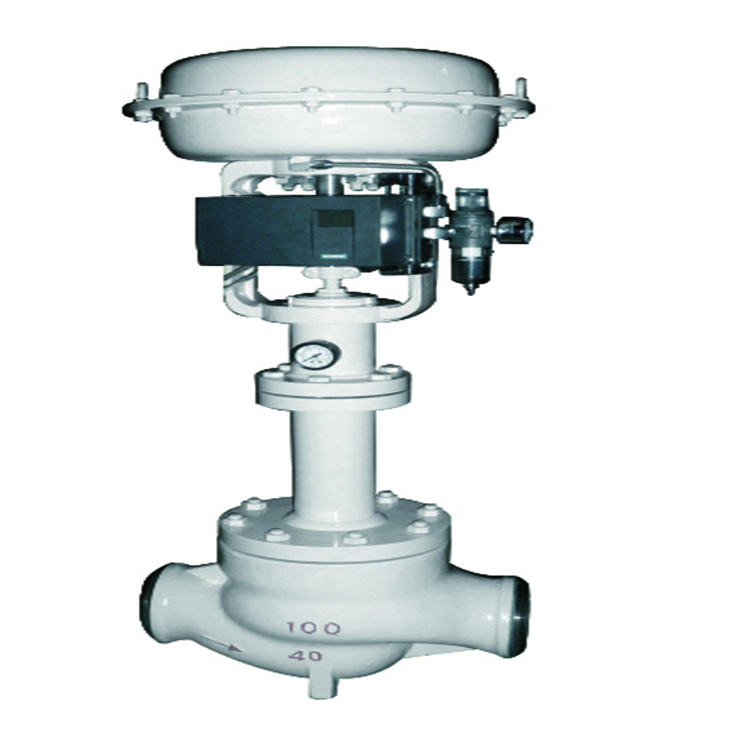
Industrial process control · Types and selection

The main types of control valves can be classified by body and trim construction, linear or rotary motion, actuator power source, and special service duty. These labels describe different features of the assembly. A globe valve, for example, describes a body style; pneumatic describes an actuator arrangement. The suitable combination depends on the process cases, control objective, pressure drop, shut-off requirement, fluid, materials, installation and project specification. A type name alone does not determine valve size or service suitability. On this page

Types of Control Valves: Quick Classification

Classification axisCommon optionsWhat the label describes
Body and trimGlobe and angle bodies; globe trim may use cage guiding. Rotary options include V-port ball, butterfly and eccentric rotary.The flow path and throttling construction
MotionLinear or rotaryHow the closure element moves through its operating range
ActuationPneumatic, electric or hydraulicThe power and control arrangement that moves the valve
Service trimStandard, low-noise, anti-cavitation, staged or other engineered trimA design response to defined process conditions
Types of control valves classified by body design, motion, actuation and service trim
Concept illustration: Body design, motion, actuation and service trim are separate classification axes.

These classifications apply together to different types of control valves. A rotary V-port ball control valve can be paired with a pneumatic actuator, for example. A regulator that operates from process pressure is a related pressure-control device, but it should not be confused with an externally actuated modulating control valve. For system-level valve functions such as isolation, modulation, non-return and pressure protection, see the valve function guide.

Which service conditions change the shortlist?

Use the following questions to compare types of control valves before shortlisting a body and trim. A candidate remains provisional until the supplier checks every stated operating case.

Service concernWhat to compareWhat must be resolved before selection
Wide flow range or low-flow controlAvailable trim capacities, travel/rotation at each case, installed characteristic and package responseMinimum and maximum required flow must fall within the proposed assembly’s demonstrated controllable range; a catalog rangeability ratio alone does not establish this.
High liquid pressure dropBody and trim options, pressure-recovery behavior and pressure-staging approachAssess cavitation, flashing and velocities using actual pressures, temperature and fluid properties; an anti-cavitation label alone is insufficient.
Gas or steam noiseTrim proposal, operating travel, outlet conditions and connected pipingDefine noise acceptance and prediction basis. Identify all flow cases, gas properties and piping assumptions.
Solids, fouling or abrasive serviceFlow passages, guiding, clearances, materials and maintenance accessDescribe particle size/concentration and plugging or wear risks. Confirm that the proposed passages and trim are appropriate for the actual medium.
Demanding shut-offSeat design, leakage acceptance, differential pressure and actuator loadName the test standard/edition, class or acceptance criterion, test conditions and direction. A body type alone does not establish shut-off performance.
Utility loss or required fail positionActuator, accessories, stored energy and control circuitState which supply or signal is lost and the required valve response. Confirm the full assembly and its test basis, rather than inferring failure action from actuator type.

What makes a valve a control valve?

For the externally actuated modulating valves covered here, the control valve assembly changes its flow passage in response to a controller signal. The valve, actuator and required accessories form the final control element. The complete assembly may include the valve body and trim, actuator, positioner, signal converter, solenoid, limit switches and other specified accessories.

The process controller, measurement devices, control logic and valve work together. The valve does not control a process variable simply because it can be partially opened. It must respond over the required operating range, and the installed valve behavior must suit the process. A valve selected only by line size may have poor controllability or may not pass the required flow. A valve selected only by a generic type label may also miss shut-off, material, actuator or documentation requirements.

Control-valve duty is usually modulating, while a simple on/off valve is intended to move between defined open and closed states. Some valve designs may serve more than one duty, but that capability needs to be confirmed for the actual model, service, actuator and acceptance criteria.

Illustrative review scenario: A valve is requested at the same nominal size as the pipe, but the proposed trim passes normal flow near its closed position. The capacity may be excessive for the control duty. Compare required Cv/Kv and predicted travel at minimum, normal and maximum flow, with the actual system pressure drop and model data. Review alternative trim capacities before selecting the body size.

IEC 60534-1:2023 provides industrial-process control-valve terminology and general considerations. Its scope is a terminology/framework reference, not proof of a particular product’s certification or service suitability.

Types of Control Valves by Body and Trim

Compare types of control valves by the required flow path and control task, then check the proposed trim and actuator against every operating case. The comparison below defines screening directions; it does not establish model availability or final suitability.

ConstructionWhat makes it worth comparingSelection-changing checks
Globe body with specified plug, seat and guidingCompare when the duty calls for a defined throttling characteristic or a choice of replaceable trim arrangements. Cage guiding is one construction feature, not a separate body family.Required capacity and travel at every case; shut-off; guiding and passage cleanliness; actuator thrust; bonnet and maintenance access.
Angle bodyCompare when the piping arrangement requires a change in flow direction or the service needs review of an angle flow path.Exact body/trim geometry, flow direction, outlet conditions, piping loads and access. Flashing or erosion suitability requires application review.
Characterized V-port ballCompare a rotary design when a shaped port is proposed to produce the required throttling response.Port geometry and capacity curve; installed operating range; pressure recovery; seat/material limits; shut-off and actuator resolution.
Butterfly control designCompare a disc-based rotary construction when package space and flow capacity are key selection considerations.Disc/seat design, useful controllable travel, differential-pressure limits, recovery/noise behavior and actuator torque across travel.
Eccentric rotary designCompare an offset plug/disc arrangement when its specific seating and throttling geometry is offered for the process.Manufacturer drawing, flow direction, capacity curve, wear/solids review, required torque and documented shut-off basis.
Three-way bodyCompare when the process must mix two streams or divert a stream between branches.Correct mixing/diverting construction and port map, individual branch flows and pressure drops, allowable cross-port leakage and failure response.

Globe-style control valves

Globe-style control valves use a moving plug or related throttling element and a seat within a globe-pattern body. Seat arrangement and guiding describe different design features. A globe-style valve may use a single-seat or double-seat arrangement; cage guiding is a trim/guiding feature that can occur within a globe-style construction. Identify both the body pattern and the actual trim arrangement in the datasheet. For general construction and port-arrangement context, see Spirax Sarco’s control-valve tutorial. Its steam/water examples do not establish the internal construction or performance of a Raymon product. The guiding and trim arrangement, pressure drop, required capacity, shut-off, maintenance access and fluid cleanliness all affect the selection.

A globe-style label does not state the valve’s capacity, leakage acceptance, control range or suitability for a specific pressure drop. Those details must be specified and checked for the service. Where a particular product is being considered, review its approved datasheet and drawings. Raymon’s globe control valve and cage-guided control valve pages provide product-specific review routes; they do not replace tag-level sizing or approval.

Angle control valves

An angle control valve changes the direction of flow through the body. Its layout may help address a piping arrangement or particular flow-path requirement, but the body form alone does not prove that it will reduce erosion, flashing, noise or pressure loss. Review inlet and outlet conditions, piping loads, flow direction, available space, maintenance access and the actual trim design.

See the angle control valve page for the product-specific configuration questions.

Rotary control valves

Rotary control valves regulate flow through angular movement. Examples include characterized V-port ball, butterfly and eccentric rotary designs. They may be considered where quarter-turn movement or the intended body arrangement fits the installation, but performance depends on the selected construction and the complete operating range.

Compare required flow capacity, installed flow characteristic, shut-off, pressure recovery, actuator output, control resolution, materials and maintenance needs. The V-port ball control valve is one product-specific route for reviewing a characterized rotary design. Do not assume that a general-purpose isolation ball or butterfly valve is suitable for continuous throttling without the manufacturer’s application confirmation.

Three-way, diaphragm and pinch arrangements

Three-way designs may be considered for mixing or diverting duties when the required flow paths, operating cases and leakage criteria are defined. Diaphragm and pinch-style arrangements may be relevant in particular process services, but the media, solids, temperature, pressure, cleaning method, materials and maintenance requirements must be checked against the exact product construction.

Specify these types only after confirming the offered model and its service envelope. For abrasive, corrosive, slurry, hygienic or high-purity duty, document the particular material, construction, cleaning and acceptance requirements.

Two-way throttling or three-way mixing and diverting?

A two-way control valve varies the restriction in one flow path. A three-way arrangement connects three ports for a specified mixing or diverting task. For mixing, define the two inlet streams and combined outlet; for diverting, identify the common inlet and the two outlet branches. Use the supplier’s port diagram rather than assuming port letters or flow arrows are universal.

Supply each branch flow and its corresponding inlet/outlet pressure for the operating cases. Confirm the body/plug arrangement is intended for the specified mixing or diverting direction, plus the allowed cross-port leakage and required response on utility loss. A three-way valve is not automatically interchangeable between these duties. The linked Spirax Sarco tutorial illustrates two-port and three-port arrangements in its steam/water context; apply the exact product and process limits to an industrial project.Illustrative assembly description

“Two-way globe body, single-seat cage-guided trim, pneumatic linear actuator, positioner and specified accessories” combines the body/port arrangement, seat/guiding design, motion and actuator in one description. Capacity, characteristic, materials, shut-off, failure action and test requirements remain separate datasheet decisions. This example is not a product offer or a sizing result.

Linear and Rotary Types of Control Valves

Schematic comparing straight-line stem travel with angular rotary movement in control valves
Engineering schematic: Linear and rotary describe closure-element motion; they do not identify the actuator power source.

Linear-motion valves move the closure element along a straight path; rotary valves turn it through an angular range. This describes movement, not the power source or the controlled process variable.

Review pointLinear-motion designRotary design
MovementStem travelAngular rotation
ExamplesGlobe and angle bodies, including applicable cage-guided trim arrangementsV-port ball, butterfly, eccentric rotary
Installation questionsStem clearance, actuator envelope, access and supportRotation clearance, mounting orientation, actuator interface and access
Engineering checksRequired travel, guiding, trim, pressure drop and shut-offCharacteristic, pressure recovery, range, shut-off and actuator output

The table screens types of control valves by motion. Neither motion type is inherently best for every application. Compare the actual design, process conditions and control-loop requirements.

Types of Control Valves by Actuation

Generic diagram of pneumatic, electric and hydraulic actuators as alternatives for a control valve
Concept illustration: Actuation is a separate selection axis from valve body and trim construction.

Pneumatic actuation

A pneumatic actuator uses compressed air to move the valve. The specification should define available supply pressure, signal and control interface, required travel or rotation time, operating frequency, accessories and the required response to loss of air or power. Define the required safe state from the process safety and control philosophy; do not infer it from the word “pneumatic.”

Illustrative review scenario: An actuator is selected using normal air supply and normal differential pressure, yet the required failure stroke must occur at a different load. That leaves the worst-case thrust or torque unconfirmed. Check the load throughout travel, maximum applicable differential pressure, minimum utility, packing/seat friction, accessory demand and agreed margin; then verify the specified failure response of the complete package.

Electric actuation

An electric actuator uses electrical power and may include a control unit, position feedback and other package accessories. Confirm supply voltage and frequency, duty, modulation requirements, environmental classification, controls, response time, interface and failure strategy. The exact actuator and valve combination must be checked against the process load throughout travel.

Hydraulic actuation

Hydraulic actuation may be considered where the project provides and accepts a suitable hydraulic power and control arrangement. Confirm the required supply, control interface, response, package scope, failure response and maintenance provisions. Selection depends on the complete installation and service requirements.

Actuator type is a separate choice from body construction. A globe body can be configured with an appropriate actuator, just as selected rotary bodies can be automated, subject to model-specific interfaces and engineering confirmation.

Self-operated pressure regulators

A self-operated regulator uses energy from the process medium or another directly sensed process condition to regulate pressure or another defined variable without the same external controller-actuator arrangement used by a typical modulating control valve. The exact device and sensing arrangement matter. See the regulating valve selection guide when the requirement is pressure regulation by a self-operated device.

Types of Control Valves for Special Service

Some designs use specialized trim or flow paths to address a defined noise, cavitation, flashing, pressure-staging or erosion concern. An “anti-cavitation” or “low-noise” name indicates a design objective; it does not guarantee elimination of the phenomenon or establish a performance limit.

For liquid service, cavitation and flashing review requires relevant pressure and temperature cases, fluid properties and the valve’s recovery behavior. For gas or steam service, noise and velocity concerns require the applicable process data and sizing method. The manufacturer should identify the assumptions, selected construction and evidence supporting the proposal. Review the anti-cavitation control valve or low-noise control valve pages only as product-specific starting points.

How to choose a control valve type

  1. Define the control objective. Identify the controlled variable, required operating modes and consequence of losing control.
  2. Provide the operating cases. Include minimum, normal and maximum flow, plus startup, shutdown or upset cases that affect selection. Provide fluid composition and properties, upstream and downstream pressure, differential pressure and temperature.
  3. Screen body and trim options. Consider required capacity and control range, shut-off criterion, fluid phase, solids, pressure recovery, cavitation/flashing/noise concerns and maintenance access.
  4. Review materials and interfaces. Specify body, trim, seat, packing and gasket requirements, end connection, pressure-temperature rating, flow direction and installation constraints.
  5. Coordinate the actuator and controls. Define power or utility, control signal, feedback, accessories, required response time and failure action. Confirm the valve-actuator package against the maximum load cases.
  6. Complete project sizing and documentation review. Use a recognized sizing method with verified process data and model-specific coefficients. Record assumptions, deviations, acceptance criteria, required tests and turnover documents in the project specification.

IEC 60534-2-1 addresses flow-capacity sizing equations under installed conditions. The published scope limits its incompressible-flow equations to the relevant Newtonian-fluid conditions; it excludes several complex fluid systems and calls for caution with non-vaporizing multicomponent liquid mixtures. Identify the fluid regime and confirm that the selected method applies. Confirm the governing project edition and method before relying on a calculation.

Check rating, materials and seals as one assembly

Pressure class is a rating designation, not a fixed operating pressure. Check the applicable material group and temperature against the governing pressure-temperature basis, then confirm any more restrictive body, bonnet, bolting, trim, seat, packing or gasket limits. Operating conditions do not replace design pressure and temperature. Include minimum temperature, maximum temperature and thermal cycling where relevant.

Review wetted and sealing parts individually against the medium, concentration, temperature, velocity, solids, cleaning fluids and shutdown conditions. A suitable body alloy does not establish compatibility of the stem, trim, seat, packing or gasket. Seat and trim choices affect shut-off and wear; packing affects external leakage, friction and actuator load; gasket selection affects pressure-boundary joints. Sour, cryogenic, emissions or fire requirements need their own applicable scope and evidence when specified.

Illustrative review scenario: A body has an acceptable pressure-temperature rating, but the proposed seat or packing has not been checked against the hottest operating or cleaning case. The assembly limit may therefore be lower than the body rating. Obtain component material limits and confirm the complete proposed construction against all temperature cases before approval.

Specify the data basis, not just the numbers

Identify whether each pressure is absolute or gauge, state flow units, and give the reference conditions for gas volume where relevant. Keep design limits separate from operating cases. Supply inlet and outlet pressures for each corresponding flow case; unrelated maximum values do not define a valid sizing case. Mark missing values as open points for review.

Cv and Kv express flow capacity on different defined reference bases; record which coefficient and units the proposal uses. Rated full-open capacity is different from capacity at the predicted operating position. Use the selected trim’s coefficient-versus-travel data and applicable sizing factors; a published maximum Cv/Kv or line size does not demonstrate low-flow control, acceptable velocity or transient behavior.

Separate inherent and installed flow behavior

Linear and equal-percentage labels describe inherent flow characteristics under specified conditions. The connected system changes the pressure drop available to the valve as flow changes. Ask for the proposed trim characteristic and expected operating travel across the actual system cases; a characteristic label alone cannot establish installed control quality.

Control valve RFQ checklist

To compare types of control valves, provide the following information on the same technical basis:

  • Valve tag, quantity, controlled variable and required function.
  • Fluid composition, phase, properties and any solids or contamination.
  • Minimum, normal, maximum and relevant transient flow cases.
  • Inlet/outlet pressure, differential pressure, design and operating temperature.
  • Line size, pressure class/rating, end connections, flow direction and installation constraints.
  • Required shut-off or leakage criterion, operating frequency and control range.
  • Body, trim, seat, packing, gasket and bolting material requirements.
  • Noise, cavitation, flashing, erosion or other service limits, when applicable.
  • Actuator power or utility, control signal, accessories, feedback, response time and failure action.
  • Applicable standards and editions, inspection and test plan, witness points, documents, deviations and acceptance criteria.

Ask the supplier to identify the sizing basis, model and trim, actuator load basis, assumptions and unresolved inputs. Do not use pipe diameter or pressure class alone to determine the control valve size.

What evidence should accompany the proposal?

Compare quotations for different types of control valves against the same process cases and acceptance criteria. Record each assumption and deviation so a lower price cannot hide a different trim, actuator or inspection scope.

Review itemRequired supplier submittalPurchaser comparison point
Sizing and trim selectionSizing sheet identifying tag, process cases, fluid properties, units, method, proposed trim and relevant valve coefficientsSame cases and units; required capacity and proposed travel/rotation; disclosed assumptions and method limits.
Installed control behaviorSelected inherent characteristic and case-specific operating range; response information where specifiedConfirm the basis for low-flow control and stable modulation; do not treat catalog rangeability as installed turndown.
Actuator and controlsValve torque/thrust load basis, minimum available utility, actuator selection, fail response, signal and accessory scheduleCheck the stated load cases, utilities, required stroke time and complete package inclusions.
Materials and constructionTag datasheet, materials list and drawing showing body, trim, seat, packing and piping interfacesIdentify material and construction deviations. Confirm compatibility review against the actual medium and temperature.
Inspection and acceptanceAgreed ITP and test schedule, standards/editions, acceptance criteria, witness points and report requirementsSeparate shell pressure tests, closure leakage and functional/package tests. Add emissions, fire or other qualification only when required and supported.
Final approvalClosed clarification/deviation list and approved datasheet/drawingResolve selection-changing open points before manufacturing release; retain the documents that govern supplied scope.

For pressure-boundary and closure acceptance planning, review the valve pressure-test scope and acceptance records. Specify control-valve leakage and package functional acceptance separately against the applicable project requirements.

Review a product configuration

Use these product pages to review types of control valves and prepare configuration questions before submitting the datasheet. Final availability, construction and documentation depend on the approved scope.

Request a project-specific control valve review

Send your valve tag or datasheet with the medium, minimum/normal/maximum flow cases, corresponding inlet and outlet pressures, temperatures, line size and control objective. Add the required shut-off criterion, materials, actuator utility and signal, failure response and inspection/document scope. Attach the line class or P&ID if available. Identify missing inputs so the review can first close the data gaps, then establish a project-specific configuration and quotation basis.

Send Control Valve Data for Review

Frequently asked questions

What are the main types of control valves?

Common classifications include body and trim construction (such as globe or angle bodies with the specified trim, V-port ball, butterfly and eccentric rotary), motion (linear or rotary), actuation (pneumatic, electric or hydraulic) and special-duty trim. These are separate classification axes, so a valve can fit one option in more than one category. What is the difference between globe and rotary control valves?

A globe-style valve uses a linear throttling movement in a globe-pattern body, while rotary designs regulate through angular movement. Compare the actual model’s capacity, control range, shut-off, pressure recovery, materials, actuator interface and process duty rather than choosing by type name alone. Are pneumatic and electric control valves different body types?

No. Pneumatic and electric describe actuator power arrangements. The body and trim construction is a separate selection decision, and the complete valve-actuator assembly must be confirmed for the process cases. When should a self-operated pressure regulator be considered?

Consider one when the required pressure-control function and application are suited to a self-operated device. Confirm the sensing arrangement, setpoint and flow range, inlet conditions, outlet or upstream control requirement, shut-off behavior and protection philosophy. The term “regulator” covers different devices, so review the exact configuration. What information is needed to select or size a control valve?

Provide fluid properties, minimum/normal/maximum flow, pressure and temperature cases, required control objective, allowable pressure drop, line and end-connection data, shut-off criterion, materials, actuator requirements and applicable project documents. The manufacturer needs the complete cases and valve-specific coefficients to perform a project sizing review. Does a control valve type determine its Cv or suitability?

No. A construction name does not supply the flow data, operating conditions or model coefficients needed to determine capacity or suitability. Complete sizing and application checks for the actual service are required.Engineering scope

This page supports screening types of control valves and preparing an RFQ. Final size, trim, actuator, materials and acceptance depend on the complete service data and approved project documents. Confirm suitability and supplied scope through the accepted quotation, datasheet, drawings, specifications and required records.
Leave a Comment

Your email address will not be published. Required fields are marked *

Control valves

Control valves manufacturer

Thanks to the many years of experience in the production of control valves they can satisfy many industrial applications by offering you a wide range of models. In our control valve factory in China we have the ability to produce electric control valves for extreme environments , pneumatic control valve, self-operated control valve and also customize according to your specific needs!

Precautions when buying Control valve

Choice of valve type

1. To determine the nominal pressure, instead of using Pmax to cover the PN, find the corresponding PN from the table according to the three conditions of temperature, pressure and material and satisfy the PN value of the selected valve.
2. The determined valve type, its leakage meets the process requirements.
3. The working pressure difference of the determined valve type should be less than the allowable pressure difference of the valve. If not, it must be considered from a special angle or another valve should be selected.
4. The temperature of the medium is within the working temperature range of the valve, and the ambient temperature meets the requirements.
5. Consider the anti-blocking problem of the valve according to the unclean condition of the medium.
6. Consider the corrosion resistance of the valve according to the chemical properties of the medium.
7. Consider the erosion and wear resistance of the valve according to the pressure difference and the medium containing hard objects.
8. The performance and price ratio considering the comprehensive economic effect.
     You need to consider 3 issues:
  • simple structure (the simpler the higher the reliability), the maintenance is convenient, and the spare parts are sourced
  • service life
  • price
9. Optimal order.
  • Butterfly valve
  • Single seat valve
  • Double seat valve
  • Sleeve valve
  • Angle valve
  • Three-way valve
  • Ball valve
  • Eccentric rotary valve
  • Diaphragm valve

Choice of Executor

1. The simplest is the pneumatic film type, followed by the piston type, and finally the electric type.
2. The main advantage of electric actuators is that the driving source (power supply) is convenient, but the price is high, reliability, waterproof and explosion-proof are not as good as pneumatic actuators, so the pneumatic type should be preferred.
3. The old electric actuators are heavy and heavy, and we have already provided electronic small, small and highly reliable electric actuators (the price is correspondingly high).
4. The old ZMA and ZMB thin-film actuators can be eliminated and replaced by multi-spring light actuators (the performance is improved, and the weight and height are reduced by about 30%).
5. There are many varieties and specifications of piston actuators, and the old, big and stupid ones are no longer recommended, but a new light structure is used.

Material selection:

1. The valve body pressure rating, operating temperature and corrosion resistance should not be lower than the requirements of the process connection pipeline, and the manufacturer’s finalized products should be preferred.
2. Cast iron valves are not suitable for water vapor or wet gas with more water and flammable and explosive media.
3. When the ambient temperature is lower than -20°C (especially in the north), cast iron valves should not be used.
4. In the Cartesian coordinates formed by the medium temperature and pressure difference with serious cavitation and erosion, when the temperature is 300°C and the pressure difference is 1.5MPa in the area beyond the line connecting the two points, the throttling sealing surface should be Choose wear-resistant materials, such as cobalt-based alloys or surface surfacing Stellite alloys.
5. For strong corrosive media, the selection of corrosion-resistant alloys must be based on the type, concentration, temperature and pressure of the medium, and appropriate corrosion-resistant materials must be selected.
6. The valve body and the throttling part are treated separately. The throttling speed of the valve body wall is small and a certain degree of corrosion is allowed. The corrosion rate can be about 1 mm/year; the throttling part is eroded by high speed and corroded, which will cause leakage and increase. If it is large, the corrosion rate should be less than 0.1mm/year.
7. When selecting the lining material (rubber, plastic), the temperature, pressure and concentration of the working medium must meet the use range of the material, and consider the physical and mechanical damage (such as shear damage) of the valve when it acts. ..
8. The vacuum valve should not be lined with rubber or plastic in the valve body.
9. The two-position shut-off valve of the water treatment system should not be made of rubber-lined materials.
10. Typical corrosion-resistant alloy material selection for typical media:
Sulfuric acid: 316L, Hastelloy, Alloy 20.
Nitric acid: aluminum, C4 steel, C6 steel.
Hydrochloric acid: Hastelloy B.
Hydrofluoric acid: Monel.
    Acetic acid, formic acid: 316L, Hastelloy.
Phosphoric acid: Inconel, Hastelloy.
Urea: 316L.
Caustic soda: Monel.
Chlorine: Hastelloy C.
Seawater: Inconel, 316L.
11. So far, the most versatile corrosion-resistant material is tetrafluoroethylene, which is called “corrosion-resistant king“.
Therefore, the PTFE corrosion-resistant valve should be selected first, and the alloy should be selected only if it is unavoidable (such as temperature>180℃, PN>1.6).

Choice of flow characteristics

The following are preliminary selections. For detailed selections, please refer to the special materials.
1. The logarithmic characteristic is selected when S>0.6.
2. The logarithmic characteristic is selected when working with small opening and when the unbalanced force changes greatly.
3. The required adjusted parameter reflects the straight line when the speed is fast, and the logarithm when it is slow.
4. The linear characteristic of the pressure regulation system is optional.
5. The linear characteristic of the liquid level adjustment system is optional.

Action mode selection

1. It is commonly used in foreign countries to indicate that it is open or closed under fault, that is, fault open and fault close, which is exactly the opposite of my country’s air open and air closed.
2. The new light valve and fine small valve no longer emphasize the positive and negative effects of the execution machinery, so they must be marked on the endnote.

Choice of spring ranges

1. The first is to select the spring range, and also to determine the working spring range.
2. Determining the working spring range involves calculating the output force to overcome the unbalanced force. If there is any difficulty, the conditions (mainly the pressure difference when the valve is closed) should be told to the manufacturer to assist in the calculation and adjustment of the spring and the working range before leaving the factory (at present, many manufacturers do not do the calculation at all).

Choice of flow direction

1. At the throttling port, the flow of the medium in the opening direction of the valve core is flow opening, and the flow in the closing direction is flow closing.
2. The choice of flow direction is mainly single-sealed regulating valve, which includes three categories: single-seat valve, angle valve, and single-sealed sleeve valve. It is based on the specified flow direction (such as double seat valve, V ball) and arbitrary flow (such as O ball).
3. When dg>15, the flow is usually selected to be open. When dg≤15, the small-diameter valve, especially the high-pressure valve, can be selected to be closed to improve the service life.
4. Optional flow and close for the two-position switch valve.
5. If the flow-closed valve oscillates, change it and the flow-open type can be eliminated.

Choice of fillers

1. Commonly used in regulating valves are tetrafluoro “V”-shaped packing and graphite “O”-shaped packing.
2. The tetrafluoro packing has small friction, but has a short temperature difference and a short life; the graphite packing has large friction, but has good temperature resistance and long life; it is recommended to choose graphite packing under high temperature and for valves with positioners.
3. If the tetrafluoro packing is often replaced, graphite packing can be considered.

Choice of accessories

1. The accessories of the regulating valve mainly include: positioner, converter, relay, booster valve, position retaining valve, pressure reducing valve, filter, lubricator, travel switch, position transmitter, solenoid valve, Handwheel mechanism.
2. The accessories play a supplementary function and ensure the operation of the valve. Increase when necessary, not increase when unnecessary. Adding accessories when not necessary increases the price and reduces reliability.
3. The main function of the positioner is to improve the output force and action speed. When these functions are not required, it can be omitted. It is better not to bring the positioner.
4. For fast response systems, the valve does not act quickly, and a converter is optional.
5. For strict explosion-proof occasions, optional: electrical converter + pneumatic positioner.
6. The solenoid valve should choose a reliable product to prevent it from not moving when it is required to act.
7. In important occasions, it is recommended not to use the handwheel mechanism to prevent human error.
8. It is best to provide by the manufacturer and supply the assembly on the valve to ensure the reliability of the connection between the system and the assembly.
9. When ordering, the name, model, specification, input signal, output signal, etc. of the accessories should be provided.
10. To reiterate: Please pay attention to the importance of these “little things”, especially reliability. If necessary, pneumatic components such as solenoid valves can be provided. 

More Control valve related articles

Why choose Raymon Control valves?

High-quality raw materials​

Using high-quality raw materials, the quality is better than peers

Complete specifications

Complete specifications, sufficient stock, one-stop purchase

Advanced technology

Excellent workmanship, advanced equipment, let you rest assured

This control-valve guide explains sizing inputs, trim choices and actuation; final selection requires a process datasheet.

REQUEST A QUOTE FOR MORE DETAILS

All You Need to Know About Control valve

01

Introduce

what is a Control valve

The control valve is widely used in chemical production and is the most commonly used terminal control element in the production process. When a parameter we monitor in real time changes, the valve that adjusts the parameter by automatically controlling the flow of the medium is called a regulating valve.
电动高压给水调节阀
HTSW Bellows Control Valve

What is a Control valve used for?

Control valves are widely used in the industry, mainly for automatic adjustment of the liquid level, flow, pressure and temperature parameters of the equipment in the production process, and can achieve the functions of cut-off and adjustment as well as diversion.

02

Introduce

03

Introduce

ZJHX Q气动三通调节阀

how does a Control valve work

The regulating valve consists of three parts: the executive structure, the valve body and accessories. The executive structure is the pushing device of the regulating valve, which generates corresponding thrust according to the size of the signal pressure, so that the valve stem produces corresponding displacement, thereby driving the spool of the regulating valve to move. The valve body accessory is the regulating part of the regulating valve, which is in direct contact with the medium, and the throttling area of the regulating valve is changed by the action of the valve core to achieve the purpose of regulation.

Control Valve Structure​

The regulating valve is mainly composed of valve body, valve seat, valve core, valve stem, sealing packing push rod, lower diaphragm cover, compression spring, diaphragm, upper diaphragm cover and other components.

The regulating valve can be divided into three parts, namely valve body, actuator and accessories. In terms of structure, the valve body of the regulating valve is not very different from the valve body of the ordinary globe valve. It is mainly reflected in the design of the channel and the valve core, and more attention is paid to the control of the flow rate. Due to the flow regulation, there will be a blocking effect. The rapid change of pressure difference is prone to flash evaporation and cavitation, which will cause damage to the valve body and valve core, so the hardness and cavitation resistance of the material are higher than those of ordinary globe valves.

what is a Control valve size

When control valve professionals talk about “Control Valve Sizing“, they mean choosing the right valve for the control process.
Choosing the right size valve is an important part of the process, but there are other equally important considerations.
The size of the control valve should be selected for the maximum flow required for the operating range of 60% and 80% opening and the minimum flow rate required for not less than 20% opening. The idea is to use as much of the control range of the valve as possible while maintaining a reasonable, but not excessive, the safety factor as much as possible.
If the valve is too small, it will be effective because it will not be able to pass the required flow. In practice, valves according to size are quite rare. Typically, the valve is too large. An oversized control valve will cost more than is necessary, but more importantly, an oversized valve will be sensitive. Small changes in valve
position cause large flow changes. This would make it difficult or even impossible to adjust exactly to the desired flow. Any stickiness caused by friction will be amplified by an overly sensitive oversized valve, and the accuracy of flow control will be reduced.
Control Valve Structure​

04

Introduce

05

Introduce

How to Install a Control valve

The regulating valve is a precision instrument, no matter how good it is, if it is not installed according to the specified requirements, it cannot be used correctly, especially new pipelines and new valves will cause many problems during transportation and installation. Correct installation method , which can ensure the normal operation of the regulating valve, which is also very important for the later maintenance, maintenance and use.
1. In the initial stage of commissioning and overhaul of the newly installed regulating valve, attention should be paid to taking isolation or dismantling measures when the process pipeline is purging to prevent the medium from being blocked due to welding slag and rust in the pipeline at the choke and guide parts. smooth, or the packing is too tight during the maintenance of the regulating valve, resulting in increased friction, resulting in the phenomenon that the small signal does not act and the large signal acts too much.
2. When installing the pneumatic control valve, pay attention to the air opening and air closing of the control valve to prevent the internal leakage of the valve due to the discomfort of the length of the control valve stem.
3. In order to prevent cavitation, the following points should be paid attention to during the original selection and installation:
჻ Try to install the regulating valve at the lowest position of the system, so that the inlet pressure and outlet pressure of the regulating valve can be relatively increased;
჻ Install a globe valve or orifice plate upstream or downstream of the regulating valve to change the original installation pressure drop characteristics of the regulating valve;
჻ Flashing or cavitation can also be effectively prevented with special anti-cavitation internals, which can change the flow rate of the fluid in the regulating valve, thereby increasing the internal pressure;
჻ Try to choose a control valve with a harder material, because when cavitation occurs, for such a control valve, it has certain erosion resistance and wear resistance, and can make cavitation exist under certain conditions without damage. The inner parts of the control valve, on the contrary, for the control valve of soft material, when cavitation occurs, the inner parts of the control valve will wear quickly. 

4. The regulating valve should generally be installed upright, and should be supported if it needs to be tilted.

5. The flow direction of the medium must be consistent with the arrow of the valve body.

6. The installation position of the regulating valve should be easy to observe, operate and maintain.

7. The signal tube of the actuator should have sufficient expansion and contraction allowance, and should not hinder the action of the actuator.

For details, see the Control Valve installation video.

HCB气动平衡笼式调节阀

Control valve application scenarios

The regulating valve, also known as the control valve, is the control component of the fluid conveying system. By using the power output by the regulating control unit to change the flow, pressure, temperature, liquid level and other parameters of the medium, it is generally composed of the actuator and the valve body. constitute. The functions of the regulating valve include regulation, voltage stabilization, diversion, diversion, cut-off, etc., which can realize the correct distribution of the flowing medium and play an important role in the development of industrial automation and intelligence. The regulating valve is one of the important components to realize automatic production and intelligent manufacturing, and the market demand continues to grow.
Divided according to the driving mode, the control valve can be divided into electric control valve, pneumatic control valve, hydraulic control valve, self-operated control valve and other product types, which can transmit non-corrosive medium and corrosive medium. Steam, liquid, oil, mud, etc. At this stage, regulating valves are widely used in many fields such as petroleum, natural gas, mining, energy, nuclear industry, electric power, water conservancy, metallurgy, chemical industry, medicine, textile, papermaking, food and beverage, urban water supply and heating, environmental protection, etc. very broad.
With the continuous advancement of science and technology and the continuous upgrading of technology, the first generation of control valves has been gradually eliminated, and the second and third generation of control valves have become mainstream products in the market. The third-generation control valve has improved regulation performance, improved precision, simplified operation, and outstanding intelligent features. It can be connected to a computer for self-diagnosis, which greatly reduces the failure rate. In order to reduce costs and increase efficiency, many industries have begun to transform into automation and intelligence. In the control system of industrial equipment, the proportion of third-generation control valves is increasing. Therefore, the current market demand for third-generation control valves is hot. 

06

Introduce

OEM & ODM Raymon Control Valves Applications

T40H water supply rotary control valve

T40H water supply rotary control valve-recommended for petroleum industry

T40H water supply rotary control valve is suitable for medium and low pressure boiler feed water pipes and high pressure heater drain pipes. By rotating the cylindrical valve disc to change the area of the window formed by the valve seat, so as to achieve the purpose of regulating flow. The rotary opening and closing angle of the water supply rotary control valve is 60°, which is indicated by the opening indicator plate above the control valve. It can be equipped with electric actuators for remote automatic operation.

电动高压给水调节阀

Electric high pressure water supply control valve-recommended power station industry

In the field of industrial automation process control, the high-pressure water supply electric regulating valve is the final control element that changes the process parameters such as medium flow, pressure, temperature, liquid level, etc. by means of power operation by accepting the control signal output by the regulating control unit. Generally consists of actuators and valves.

ZMHN Lever type pressure control valve

ZMHN Lever type pressure control valve-recommended for metallurgical industry

ZMHN pressure regulating valve is composed of lever heavy hammer type diaphragm actuator and regulating valve mechanism. The post-valve type is used to keep the pressure in the pipeline behind the control valve at a constant value, and the adjustment signal is obtained from the pipeline behind the valve; the front-valve type is used to control the pressure in the pipeline in front of the valve to a constant value, and the adjustment signal is obtained from the pipeline in front of the valve. Obtained, because the direct-acting pressure regulating valve has the advantages of simple structure, reliable action, convenient maintenance, fireproof and explosion-proof, it is used in the metallurgical industry.

HTSW Bellows Control Valve

HTSW Bellows Control Valve - Recommended for chemical industry

The valve core adopts a single-seat plunger structure with an upper guide, and the upper valve cover adopts a bellows sealing structure to prevent the medium in the pipeline from leaking from the valve stem and packing seal. The bellows are made of high-quality stainless steel, which is anti-corrosion and has a long service life. The packing will age and wear over time, and it forms a double seal with the bellows, which greatly improves the reliability. The flow channel of the valve body is S-shaped, with small flow resistance and large flow. Especially suitable for strong corrosive, toxic and radioactive media.

ZZYP Self-operated control Valve

ZZYP self-operated pressure regulating valve - recommended for machinery manufacturing industry

ZZYP self-operated pressure regulating valve does not need external energy, and uses the adjusted self-energy as the power source to introduce the actuator to control the position of the valve core, change the pressure difference and flow at both ends, and stabilize the pressure before the valve (or after the valve). It has the advantages of sensitive action, good sealing performance, small fluctuation force of pressure set point, etc.

Strength customers​

Control Valve:Ultimate Guide

Control valve type

Control valve, also known as control valve, is a device in the field of industrial automation process control, which uses power operation to change and adjust process parameters such as pipeline medium flow, pressure, temperature, and liquid level. It is mainly composed of operating actuator and regulating valve body. It accepts relevant signals and changes the opening of the valve, so as to achieve continuous adjustment of the process parameters of the pipeline medium! However, there are many product types of control valves, and the control forms are changeable, and they are constantly updated and changed. Users should be familiar with this classification method! Generally speaking, the valve body of the regulating valve is universal and can be matched with electric actuators or other actuators. It can be divided into three types according to the control actuators: electric regulating valve, pneumatic regulating valve and self-operating regulating valve.

Electric control valve

Electric regulating valve is a widely used control valve, mainly composed of electric actuator and regulating valve, powered by electricity, by receiving the signal from the controller, driving to change the size of the valve switch, and adjusting the area of the fluid passage, so as to achieve Change the flow, pressure, temperature and other working parameters of the fluid.

Pneumatic control valve

The pneumatic control valve is a valve that uses compressed air as the power, and the area of the fluid passage is adjusted by the signal of the controller to change the fluid flow. The pneumatic control valve generally adopts a pneumatic diaphragm actuator, so it is also called a pneumatic diaphragm control valve.
The electric control valve does not need to take explosion-proof measures and other advantages and has a wide range of applications.

Self-operated control valve

Self-operated regulating valve, also known as direct-acting regulating valve, does not require any external energy, and directly uses the energy of the regulated medium to operate the regulating mechanism, realize automatic control, and realize the adjustment of parameters such as temperature, pressure, and flow.
According to the stroke characteristics, the regulating valve can be divided into:
  • straight stroke (single seat valve, double seat valve, sleeve valve, cage valve, angle valve, three-way valve, diaphragm valve)
  • angular stroke (butterfly valve, ball valve, eccentric rotary valve, full-featured ultra-light control valve)
The regulating valve can be divided into: manual regulating valve, pneumatic regulating valve, electric regulating valve and hydraulic regulating valve according to the driving mode, namely the pneumatic regulating valve using compressed air as the power source, the electric regulating valve using electricity as the power source, and the liquid regulating valve as the power source. Hydraulic regulating valve powered by medium (such as oil, etc.) pressure.
According to the adjustment form, it can be divided into:
჻ adjustment type
჻ cut-off type
჻ adjustment cut-off type according to the flow characteristics can be divided into:
჻ linear
჻ logarithmic (percentage)
჻ parabolic
჻ quick opening
The most commonly used classification methods are as follows:
According to the adjustment form
჻ flow characteristics
჻ use and function
჻ valve core shape
჻ special use (ie special, special valve)
჻ upper bonnet form
჻ other thermometer pressure classification has been omitted! 

Classification by use and function

1. Two-position valve: mainly used to close or connect the medium;
2. Regulating valve: mainly used for regulating the system. When selecting a valve, it is necessary to determine the flow characteristics of the regulating valve;
3. Diverter valve: used to distribute or mix media;
4. Shut-off valve: usually refers to a valve with a leakage rate of less than 1/100,000.
According to the form of the upper bonnet:
჻ ordinary type
჻ heat dissipation (absorbing) type
჻ long neck type
჻ bellows sealing type
According to the shape of the valve core:
჻ flat-shaped valve core
჻ plunger-shaped valve core
჻ window-shaped valve core
჻ sleeve-shaped valve core
჻ multi-stage valve core
჻ eccentric spool
჻ butterfly spool
჻ spherical spool

The regulating valve is used to regulate the flow, pressure and liquid level of the medium. According to the signal of the adjustment part, the opening of the valve is automatically controlled, so as to achieve the adjustment of the medium flow, pressure and liquid level. The regulating valve is divided into electric regulating valve, pneumatic regulating valve and hydraulic regulating valve, etc. Two commonly used are electric control valve and pneumatic control valve.

The regulating valve consists of two parts, an electric actuator or a pneumatic actuator and a regulating valve. Control valves are usually divided into two types: straight-through single-seat control valve and straight-through double-seat control valve. The latter has the characteristics of large flow capacity, small unbalance and stable operation, so it is usually especially suitable for large flow, high pressure drop and leakage. few occasions.

The flow capacity Cv is one of the main parameters for selecting the control valve. The flow capacity of the control valve is defined as: when the control valve is fully opened, the pressure difference between the two ends of the valve is 0.1MPa, and the fluid density is 1g/cm3, the hourly flow path The flow rate of the regulating valve is called the flow capacity, also known as the flow coefficient, expressed in Cv, and the unit is t/h.

The flow characteristic of the regulating valve is the relationship between the relative flow of the medium flowing through the regulating valve and its opening degree under the condition that the pressure difference between the two ends of the valve remains constant. There are three kinds of flow characteristics of regulating valve: linear characteristic, equal percentage characteristic and parabolic characteristic.

The meanings of the three fluence properties are as follows:

  1. Equal percentage characteristic (logarithm)

The relative stroke and relative flow of the equal percentage characteristic are not in a linear relationship. At each point of the stroke, the flow change caused by the unit stroke change is proportional to the flow at this point, and the percentage of flow change is equal. Therefore, its advantage is that when the flow rate is small, the flow rate change is small, and when the flow rate is large, the flow rate change is large, that is, it has the same adjustment accuracy at different opening degrees.

  1. Linear characteristic (linear)

The relative stroke of the linear characteristic and the relative flow are in a linear relationship. The flow change caused by the change of unit stroke is constant. When the flow rate is large, the relative flow value changes little, and when the flow rate is small, the relative flow value changes greatly.

  1. Parabolic characteristics

The appropriate inherent flow characteristic depends on the process gain, pressure-drop distribution and required control range. Linear and equal-percentage trims should be evaluated through valve sizing and the installed system characteristic rather than ranked universally.

Pressure regulating valve, also known as self-operated balancing valve, flow control valve, flow controller, dynamic balancing valve, and flow balancing valve, is an intuitive and simple flow regulation and control device. Under the action of water, the valve can automatically eliminate the residual pressure head of the pipeline and the flow deviation caused by the pressure fluctuation, and keep the set flow unchanged no matter how the system pressure changes. These functions of the valve make the flow adjustment of the pipeline network completed at one time , turn the network adjustment work into a simple flow distribution, and effectively solve the hydraulic imbalance of the pipe network.

The pressure (pressure) at which the substance is in a critical state is called the critical pressure, so what is

the critical pressure of the control valve? Each medium of the control valve is different, the critical

temperature is different, and the critical pressure is also different.

For example: the critical pressure of water is 22.12MPa and the critical temperature is 374.3℃. That is to say,

when the water exceeds the critical temperature of 374.3°C, no matter how the pressure is increased, the gas

(water) cannot be liquefied. When the critical temperature of water is 374.3°C, the minimum pressure to

liquefy the gas (water) is 22.12MPa.

The actuator is the supporting product of the electric regulating valve and is composed of a motor, a reducer, a transmission shaft and a bearing, etc. Its function is to accept the signal from the regulator (electrical signal or air source pressure) to drive the valve core to complete the opening action and realize flow control.

The actuator of the electric regulating valve is different from the ordinary valve structure!

It does not adjust the flow by changing the throttling area, but by changing the stroke.

Therefore, the electric regulating valve has obvious advantages over the traditional throttling instrument:

small size and light weight

  • large output torque
  • sensitive response
  • convenient and flexible operation
  • remote control and so on

There are many types of actuators for electric control valves, and there are two commonly used types: diaphragm actuators and piston actuators.

Diaphragm actuator is a double-acting piston-type actuator composed of a porous diaphragm divided into two halves.

Its characteristic is that when the medium pressure increases, the partition plate is moved to generate a top-opening force, which pushes the diaphragm and the push rod down to compress the medium in the spring cavity to produce a shut-off action.On the contrary, the diaphragm is pushed up to close the channel to achieve the purpose of adjusting the flow.

The advantages of this type of actuator are large thrust, long stroke and good sealing performance.

The disadvantage is that it is easy to be deformed under pressure and requires high processing accuracy.

Therefore, it is generally used in high-pressure and large-diameter occasions, such as high-pressure three-way cock butterfly check valve, etc. The difference between the diaphragm type and the piston type is that the former is single-acting and the latter is Multi-function, the former is suitable for low pressure difference and small flow, the latter is suitable for high pressure difference and medium or above flow.

The flow capacity Cv value is one of the main parameters for the selection of the control valve.

The definition of the flow capacity of the control valve is: when the control valve is fully opened, the pressure difference between the two ends of the valve is 0.1MPa, and the fluid density is 1g/cm3, The flow rate of the flow path regulating valve per hour is called the flow capacity, also known as the flow coefficient, expressed in Cv, the unit is t/h, and the Cv value of the liquid is calculated as follows.

The nominal diameter DN of the regulating valve can be determined by looking up the table according to the value of the flow capacity Cv.

The flow coefficient Kv of the regulating valve is an important parameter of the regulating valve, which reflects the ability of the regulating valve to pass the fluid, that is, the capacity of the regulating valve. According to the calculation of the flow coefficient Kv of the regulating valve, the diameter of the regulating valve can be determined. In order to correctly select the caliber of the regulating valve, the Kv value of the rated flow coefficient of the regulating valve must be correctly calculated. The definition of the rated flow coefficient Kv of the regulating valve is: under the specified conditions, that is, the pressure difference between the two ends of the valve is 10Pa, and the density of the fluid is the number of flow through the regulating valve at the rated stroke.

What is the difference between CV and KV in a control valve?

When calculating the flow coefficient of the control valve, many technical staff basically do not distinguish between Kv and Cv in order to save trouble, and the final calculation results are different. Both Kv and Cv represent the flow capacity of the valve.
Although they are related to a certain extent, they are essentially different:
Cv: is the flow coefficient in imperial units, and refers to the number of US gallons per minute flowing through
the regulating valve under a pressure drop of 7KPa at a temperature of 15.8°C.
Kv: The flow coefficient of the international system of units, which refers to the cubic number of water flowing
through the regulating valve per hour under the pressure drop of 105Pa at a temperature of 5~40℃. 

How much air does the control valve use? 

The air consumption depends on the frequency of adjustment, and has nothing to do with the cylinder or the film. The air consumption of the regulating valve is continuous, and the on-off valve is intermittent, but the instantaneous air consumption during operation is very large, which cannot be considered with the usual air consumption.
How much gas is used to adjust the pneumatic valve?
The air consumption depends on the frequency of adjustment, and has nothing to do with the cylinder or the film, it is continuous, and the on-off valve is intermittent, but the instantaneous air consumption is very large during the action, which cannot be considered with the usual air consumption.
In theory, the pneumatic actuator does not consume air when it is static, but the control part such as the valve positioner consumes air.
Pneumatic instrument design generally requires static less than or equal to 5 liters per minute (0.4MPa), which is actually 8~12 liters.
The actual air consumption of the pneumatic actuator is related to the frequency of action, so when the quantity is larger in the pneumatic instrument, the margin is enlarged.
When the number of pneumatic units is less than 20 and includes an actuator, an air storage tank should be used.
Air consumption
When the cylinder reciprocates for one stroke, the air consumption in the cylinder and the piping between
the cylinder and the reversing valve (under standard atmospheric pressure)
Maximum air consumption rate
When the cylinder piston moves at the maximum speed, the amount of air consumed per unit time (under standard atmospheric pressure)
Maximum air consumption of the cylinder:
Q = piston area x piston speed x absolute pressure
The usual formula is:
Q = 0.046D²v (p+0.1)

Priority commercial page

Treat the valve, trim, actuator and controls as one dynamic package

A control valve selected from maximum flow alone can be unstable, noisy or rapidly damaged. Every operating case must be sized and checked against the chosen trim and actuator.

Who this page is for

Process-control engineers, EPC instrument teams and package buyers.

Primary search task

Control-valve technical evaluation and RFQ preparation. Search-volume data is not asserted without connected GSC or keyword-tool evidence.

DecisionWhy it changes the offerRecommended review routeEvidence to request
Sizing envelopeMinimum, normal and maximum cases may require different travel and pressure-drop margins.Calculate every credible case and review installed behavior.Process cases and sizing sheet
Energy managementCavitation, flashing, gas noise and velocity damage require different responses.Identify the physical mechanism before selecting trim.Noise/cavitation/velocity calculation
Shutoff and packingLeakage class, emissions and packing friction affect trim and actuator.State shutoff conditions separately from control cases.Leakage requirement and sealing design
Actuator and controlsFail action, utility limits and accessories determine functional performance.Size thrust with packing, unbalance and safety margin.Actuator calculation and hook-up
Application decision patterns

Three realistic contexts to test the specification

These are illustrative engineering decision scenarios—not named customer projects, installed-performance claims or promises of suitability.

High-drop liquid service

Decision pressure: Cavitation can damage trim and downstream pipe.
Engineering route: Review staged pressure reduction and outlet velocity.

Anti-cavitation claims require case-specific calculation.
Gas pressure control

Decision pressure: Aerodynamic noise and outlet Mach number can govern sizing.
Engineering route: Evaluate low-noise trim, body size and downstream treatment together.

Acoustic prediction inputs must be documented.
Flashing process liquid

Decision pressure: The vapor phase persists downstream and cannot be eliminated by anti-cavitation trim.
Engineering route: Manage velocity, erosion path, body pattern and materials.

Final solution requires thermodynamic case data.
E-E-A-T and approval evidence

Evidence that should exist before technical approval

Sizing calculation for every caseTrim characteristic and travelNoise/cavitation reviewActuator thrust and utility basisAccessory schematicFunctional and leakage test plan
Content responsibility and limits. This page supports early technical and commercial evaluation. Raymon Valve’s content team maintains the public guidance; the responsible project engineer, purchaser and quality reviewers must approve order-specific construction, calculations, standards/editions, materials, tests and deviations. Application patterns above are not customer case studies. Review the technical content and evidence policy. Updated 29 July 2026.
Next decision

Send all flow cases and the control/fail-action philosophy

Mark confirmed inputs, preliminary assumptions and open questions separately so the first review can focus on risk.

en_USEnglish
Scroll to Top